The correct selection of a circuit breaker release will protect electrical equipment, safety equipment and distribution network wiring from overload and short circuit overcurrent. One or more releases with different selectivity are installed in circuit breakers (AB). These components protect the electrical circuit from overcurrent and short-circuit overcurrent. There are relay protection devices with instantaneous release and delayed operation.
Types of circuit breaker releases
The load circuit protection device is a direct-acting relay capable of recognizing the onset of an emergency and preventing the development of negative processes. There are several types of tripping devices:
- releases with overcurrent protection and fixed factory settings (thermal components with time delay and electromagnetic instantaneous ones);
- devices for selective recognition of overload from short circuit with settings for rated current and delay time (semiconductor, electronic);
- components with extended functionality (independent, minimum and zero voltage).
Thermal
Thermal release is a bimetallic plate made of 2 strips soldered (welded or riveted) together. The materials for the strips are selected in such a way that the coefficient of thermal expansion of one differs from that of the other. When electricity passes through, the bimetallic joint heats up more, the greater the current in it. If the metal of the bottom strip elongates less when heated than the metal of the top, the bimetallic strip will bend downward.
At a certain current value, bending the plate is enough to open the contacts of the machine. The thermal release reacts to overload ≥30% of the rated current value, therefore it is used for overload protection. The response time is inversely related to the amount of current passing. In different communication devices it ranges from seconds to 1–2 hours.
Electromagnetic
The electromagnetic component is a coil (solenoid) with a core that moves under the influence of the electromagnetic field of the current passing in the winding. The core, overcoming the resistance of the spring, triggers the element that disconnects the circuit. Direct-acting electromagnetic relays recognize a short circuit (exceeding the current value by several times the rated value) and, depending on the response sensitivity, the machines are assigned classes A, B, C and D.
Most often, class B and C circuit breakers are used in household networks, in which the trip delay is designed for 3–10 times the rated current.
Releases of this type operate in a fraction of a second and are instantaneous elements, used for protection against short-circuit currents.
Thermomagnetic or combined
Often the thermal and electromagnetic releases are connected in series. The tandem provides current selectivity: one element monitors currents in the overload zone, and the other protects electrical circuits from short-circuit overcurrents. Some manufacturers call this combination a combined release. In foreign catalogues, a series connection of 2 devices is called a thermomagnetic release.
Semiconductor
The semiconductor device is built on a measuring element IE and an actuating element - an electromagnet with a control unit. The measuring element is assembled on a current transformer.
The electromagnet acts on the free release mechanism of the machine, causing the circuit to open ↔ close. The release is triggered when a current flows in the circuit that exceeds the overload or short circuit setting. This setting is used as an additional protection to the main short circuit overcurrent protection.
The settings for the overload current (1.25–6.0 of the rated current) and overload time (4–16 seconds) of the semiconductor release are indispensable in the home electrical network. They allow you to flexibly configure the operation of the machine when powering the SBT with electric motors, taking into account the high currents at the moment of starting the household unit.
The required current and time delay values are set using switches. They are located on the front side of the control unit.
Electronic
The electronic analog block diagram does not differ from the semiconductor release. The measuring device measures the AB current using a circuit on the transformer. The electronic module of the control unit compares the received and set value and supplies the control voltage to the electromagnet.
An expanded set of options allows for logic selectivity using a controller built into some devices. The electronic release is distinguished by the presence of a current indicator, a large selection of settings and maximum accuracy in following the assigned task.
Independent
The independent type release remotely controls the switching of alternating (AC) and direct current (DC) electrical circuits, representing a conventional release with a distance protection option. The voltage coming through the control circuit, for example from the operator's console, is supplied to the solenoid. A magnetic field is created in the winding, the core is retracted and actuates the free release mechanism in a time of ≤0.04 s. To reset the circuit breaker, you must manually press the button labeled “Reset.”
Undervoltage and overvoltage release
Some AVs are equipped with additional minimum and zero tripping devices, which are built directly into the machine or mounted outside the housing.
This type of release responds to a voltage threshold rather than a current threshold. They turn off the automatic switch when the voltage in the electrical circuit drops below 0.35–0.7 and 0.1–0.35 of the rated voltage, respectively.
Design Features
BA88 IEK circuit breakers have a reliable mechanism for triggering thermal, electromagnetic and electronic protection.
The power contacts (current-carrying parts) are coated with a coating that improves electrical conductivity. The design of the BA88 IEK allows you to connect a wide range of additional devices. Regardless of their size, all BA88 IEK circuit breakers have a similar design, which can be divided into three functional blocks: current-carrying parts, a free tripping mechanism and a release.
Live parts
BA88 IEK switches consist of terminals for connecting external conductors, moving and fixed elements of the contact group.
The basis of the mechanical part
is the so-called "free release mechanism". This structural unit ensures reliable contact connection of current-carrying elements in the closed state and their instantaneous opening when the release is triggered. The latter, in turn, ensures that the circuit opens even if the switch handle is blocked from moving.
Releases
There are usually two types: thermomagnetic and electronic. The design of thermomagnetic releases is well known: they consist of an electromagnetic unit for protection against instantaneous overload (short circuit) and a thermal unit for protection against continuous overload (exceeding the current rating).
Some types of BA88 IEK switches have a different design of the electromagnetic unit. The electromagnet is implemented in them according to the principle of an electrodynamic system, where conductors with unidirectional currents repel, and conductors with multidirectional currents attract. Moreover, the role of the second conductor is played by a steel plate of a special shape, in which magnetization is created by alternating current flowing through the pole conductor. The countercurrents attract the plates, and if the force is sufficient, the reset rack switches the free release mechanism to the “off” position.
The electronic release is implemented on a microcontroller, which measures the amount of current flowing through each pole. The release is adjusted according to three parameters: the level of instantaneous and continuous overload current, as well as the response time delay. When a critical current value is reached within a specified time, the release, through a special relay, gives a command to the free release mechanism to turn off the circuit breaker.
Phenomena caused by overcurrents
The flow of extreme current causes the following adverse effects:
- Thermal overheating damages the insulation of conductors and operating components and causes fires. The development of this phenomenon is blocked by installing a current protection device with a response speed of ≤ 0.005 s.
- The electrodynamic force deforms and destroys conductive components, causing breakdown of the switching device. The way to combat this is to select components with increased electrodynamic resistance and correct arrangement of parts, excluding mutual EM influence.
- The magnetic field negatively affects the operation of measuring instruments, computers and other precision equipment. The impact of the field is minimized by using screens made of soft magnetic alloys (permalloy, ferrite).
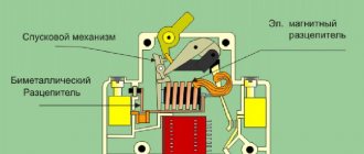
Design and principle of operation of the machine
It will be difficult to make a choice without understanding the circuit breaker design. Let's see what's hidden in a miniature box made of refractory dielectric plastic.
Releases: their types and purpose.
The main working parts of automatic circuit breakers are releases that break the circuit if the standard operating parameters are exceeded. Releases differ in the specificity of their action and in the range of currents to which they must respond. Their ranks include:
There are also zero or minimum releases, most often used as a supplement. They disconnect the network when the voltage drops to any limit value specified in the data sheet. A good option are remote releases that allow you to turn the machine off and on without opening the control cabinet, and locks that fix the “off” position. It is worth considering that equipping with these useful additions significantly affects the price of the device.
Automatic machines used in everyday life are most often equipped with a smoothly working combination of an electromagnetic and thermal release. Devices with one of these devices are much less common and used. Still, combined type circuit breakers are more practical: two in one is more profitable in every sense.
Checking the functionality of releases
The functionality check includes the following steps:
- Visual inspection of the switch. There should be no mechanical damage on the device body: chips or cracks. Pay attention to the tightness of the parts, the quality of fasteners and clamps. Make a few test manipulations of “on ↔ off” manually. In the on position, the device should click into place and then turn off freely.
- Loading the device. The test consists of determining the response time of the release when power is supplied with an adjustable current strength on a special stand. The obtained result is compared with the typical time-current characteristic of the AB model.
The modern market of electrical equipment offers the consumer a wide range of releases. These devices are equipped with devices of 1-3 phase alternating AC and direct current DC and voltage up to 1000 V.
Operation of the machine during a short circuit
Large short circuit currents can melt electrical wiring or burn insulation. To save electrical wiring, use an electromagnetic release. In case of short circuits, the mechanics of the electromagnetic release are triggered instantly, protecting the electrical wiring, and it does not have time to heat up.
However, when the contacts open, an electric arc with enormous temperature appears. An arc-extinguishing chamber is designed to protect against burnt contacts and destruction of the housing. Structurally, the chamber consists of an element with a set of thin copper plates with a small gap.
Electromagnetic and thermal protection of circuit breaker
An electric arc touching a set of plates through a copper wire connected to a contact breaks into pieces, cools down and disappears. When a short circuit occurs, gases are formed that escape through the holes in the chamber. To turn the machine back on, you need to eliminate the cause of the short circuit, or the machine will turn off again.
The culprit of the short circuit can be determined by sequentially turning off household electrical appliances. But if after turning off all the devices the short circuit does not disappear, then there is a high probability that it originated in the electrical wiring. A short circuit condition can be caused by electric lighting devices, which also need to be turned off.
electricremont.ru
Number of poles
As already mentioned, the circuit breaker has poles - from one to four.
Selecting a device for a circuit based on their number is not at all difficult; you just need to know where different types of AVs are used:
- Single-pole circuits are installed to protect lines that include sockets and lighting fixtures. They are mounted on the phase wire without touching the neutral wire.
- The two-terminal network must be included in the circuit to which household appliances with sufficiently high power are connected (boilers, washing machines, electric stoves).
- Three-terminal networks are installed in semi-industrial networks, to which devices such as well pumps or auto repair shop equipment can be connected.
- Four-pole AVs allow you to protect electrical wiring with four cables from short circuits and overloads.
The use of machines of different polarities is shown in the following video:
Loading method
During loading, the main characteristics of the machines are measured (rated current, protection operation current, protection operation time under abnormal conditions) on a special installation. All work on testing the functionality is carried out by special personnel who have access to such tests, with a certificate with a mark of admission to special work on testing electrical equipment.
The certificate must indicate the safety group and the voltage at which the employee can conduct tests (up to or above 1000V). The certificate must be signed by the chief power engineer of the enterprise that carries out the verification work. The method of loading AV in the factory must comply with GOST for low-voltage control and distribution equipment.
Equipment
In order to test (load) a circuit breaker, you need to assemble a fairly simple circuit that includes the equipment necessary for testing:
- connecting wires;
- KU - control key;
- LATR - laboratory autotransformer, for changing the load; load transformer or load transformer (LT);
- ammeter as a shunt;
- CT - current transformer.
Diagram of the device for checking AB:
The loading method requires partial dismantling of the device, and after checking its serviceability, reassembling it. The test device can be of a different type, the main thing is that an artificial short circuit current is supplied to the AV, its value is measured, and the response time of the circuit breaker protection in the electrical network is taken into account.
There are even special kits for checking AB, for example SINUS-1600, shown in the photo:
The process itself
Loading of a circuit breaker with an electromagnetic release is carried out to determine the operation time of the circuit breaker within the protected area according to factory specifications. To do this, the load current is set on the testing device, which is equal to the maximum amperage for a given type of AB and time, according to the factory specifications.
To test the thermal release, the test installation is set to three times the load current and the maximum trip time, according to the factory specifications. Usually this time is from 5 seconds. up to 0.5 min.
All steps to check the machine are discussed in detail in the video:
How to load an AV with primary current
Tests at home
All results of the work carried out are recorded in the protocol. The document reflects the magnitude of the induced amperage and the response time of the machine. The loading protocol is signed by the person conducting the tests. A sample of filling out the inspection protocol is provided below:
Test dates
The frequency of testing should be specified in the accompanying regulatory documents of the manufacturer, but the recommended test is once every three years during normal operation of the circuit breaker at the rated load current. In case of emergency operations or abnormal operation of the AV, the frequency may be changed, and an unscheduled inspection should be carried out. All recommendations apply to household circuit breakers and switches installed in industrial premises.
According to the PUE, Chapter 3.2, clause 1.8.37, the loading of circuit breakers on input and sectional protection devices, emergency lighting networks, fire alarms is 2% of AV group networks. PUE requirements for other electrical installations 1% of all installed machines.
If circuit breakers are detected that do not meet factory specifications, a test procedure is carried out for the entire batch. After loading, each device must be stamped with the logo of the laboratory conducting the test, the date of the test, and the word “Tested” or “Best before ... (date).” This indicates that the machine has been tested and is suitable for use.
This is the method used to test circuit breakers with voltages up to 1000 V. As you can see, you can load a machine even with a device assembled at home, the main thing is to know the safety precautions and testing technology. We hope that now you know what and how to do in order to independently check the breaking capacity of the protection device.
It will be interesting to read:
- Why does the RCD in the panel trip?
- How to check the performance of the heating element
- How to use a megger
Varieties of the model range
Many home craftsmen prefer to use time-tested independent releases. Such units operate solely under the influence of voltage, which gradually passes through the main circuit of the circuit breaker. The great popularity of such installations arose against the background of the fact that each master can control the system remotely, which is not provided for in other categories of releases.
An automated switch helps to timely disconnect from the power supply absolutely all devices and other sources that operate using electricity. This function is especially important in situations where there is a noticeable voltage deviation in the network from the norm specified by the consumer
But it is important to take into account the disadvantages that are associated with the conversion of energy into heat release. The presence of such a factor may result in the switch being disconnected improperly
Modern Z-ASA/230
Manufacturers note the fact that turning off ventilation in the event of a fire through an independent switch of this series occurs extremely quickly. This model comes with high quality moving modules and six pairs of contacts. This device is especially relevant for impulse switches. The unit works great in extreme conditions where there is high humidity. The device is often used by specialists for remote control. The level of current conductivity is equal to 4.5 microns.
Improved modifications for 30A
This type of release for a circuit breaker is manufactured with a special code expander. The final output voltage is equal to 35 V. The smooth operation of the unit is associated with diode rectifiers. All contacts are mounted on movable plates.
Experts have provided for the presence of transceivers with trimming resistors. Many models in this category are connected to electrical panels via high-quality capacitor units. To prevent the negative impact of unscheduled overloads on the network, expansion dinistors are used.
Unit IEK РН47
Experts confidently claim that this release is one of the most popular. The compactness of this model is of great importance. Reliable fixation with the shield is ensured thanks to small capacitor units. In addition, the model has only two rectifiers, and all contacts are movable.
The expander itself is located in the lower compartment of the structure along with the relay. The presence of a transceiver is not provided.
Particular attention should be paid to the operating parameters of the independent release - the output voltage is within 40 V. The maximum network load should not exceed 30 A
In addition, manufacturers have conducted numerous studies that have shown that the minimum trip temperature is within -10˚C. The unit is not at all afraid of exposure to high humidity. All wiring is insulated in a special way for safe operation of the device.
Household SHUNT 250 VAC
This model of independent release is produced on the basis of a diode rectifier, which is located above the relay
Attention should also be paid to the operating parameters of the system, which are 44 ohms. Standard threshold overload is equal to 24 A
A miniature capacitor unit is used to connect the modification.
All conductors are equipped with powerful insulators. The unit is equipped with three pairs of resistors, securely fixed above the rectifier. Manufacturers did not provide for the presence of a stabilizer. This makes this model ideal for low-power drives.