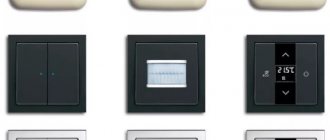
Smart plug features
To fully understand, you need to understand what functions such a device performs and what properties it has. In general, the main function of such an outlet is to turn on electrical appliances using a remote control.
In the photographs of the smart socket you can see that this device does an excellent job of remotely turning on a kettle or boiler.
Agree that you don’t always want to get up and go warm up the kettle or start the boiler, especially in the morning. With this device you will have time to fully wake up and still have hot water.
This device can also help with time management, since the remote control allows you to turn on appliances from anywhere, which will allow you to turn on multicookers, boilers and other electrical appliances on the way home.
Malfunctions
The device does not respond to the command signal or its range is greatly reduced.
In this case, check the battery charge of the control panel or move the socket to another convenient location (the radio signal may be blocked by obstacles).
Spontaneous switching on of the radio adapter. In this case, reset the radio code, change the channel, and perform the synchronization procedure again.
Types of smart sockets
The choice of this product on the market is very wide, so consumers do not always understand what these sockets are. Each type differs from the other in design, installation method, control method, and others.
According to the installation method, smart sockets are divided into:
- Overhead smart socket. This type is something like an adapter, since it connects to a regular outlet. They have gained their popularity due to the fact that the process of connecting them is very simple, and everyone can understand the instructions for these smart sockets.
- Sockets that are mounted into walls. This option is suitable for those people who are doing a full renovation of the room, because the process of installing such an outlet involves connecting the device to the general electrical wiring.
According to management methods, it is customary to distinguish:
- Using radio control. A smart socket with a remote control is designed to control devices at a certain distance (usually up to thirty meters).
- Via SMS messages. These devices can turn on the devices as soon as a message is received from the owner.
- Using the Internet. This type is the most popular, as you can control such a device from anywhere on Earth.
By design features we can distinguish:
- Single, independent models.
- Sockets that have outputs for remote control of several devices.
- Groups of devices in which one device acts as the main link, and the main ones are dependent on it.
- Extension sockets. This type of device can control both all outputs and each one separately.
Several diagrams for self-assembly
Now let's look at several diagrams for assembling a socket with a remote control with your own hands, which were found on the network. Let’s not hide that these circuits are generally suitable for many other devices for controlling electrical equipment at a distance, so we will try to select the most interesting ones that require different levels of skill.
Moreover, we chose the first two schemes with radio control, since sockets with IR control, despite the fact that they are much cheaper, will not save you from the problem of a “burning iron” - you left the house and forgot whether you turned off the electrical appliance.
On ready-made modules
The easiest way to assemble a remote-controlled socket is in just a couple of hours using a set of ready-made modules that can be easily purchased on the Internet. The device has pretty good characteristics - switched load up to 2 kW and 10A, range up to 50 meters. Although we will say that the cost is low (you will have to pay about 2 thousand rubles for all the blocks), you can assemble it yourself for less.
We will need:
- receiver module with switching device MP912;
- The power supply for it (you can assemble it yourself, but it’s better to buy it in pairs, especially since there’s a discount on the set) WP1245;
- MP910 remote control.
The price for everything, if you purchase a receiver and power supply, is approximately the same as for ready-made sockets with radio remote control, but, nevertheless, it will be done with your own hands.
Assembly does not require any special knowledge of radio engineering, the main thing is to be able to read circuit diagrams and hold a soldering iron and wire cutters in your hands. Here is a diagram of connecting the receiver and power supply.
Receiver connection diagram
The socket can be assembled in several versions:
- like a regular overhead (you will have to find additional volume in the case, for example, by removing the switch in a socket with a switch);
- as built into the wall (in this case, additional volume for electronics can be found in the volume of the wall, not forgetting about cooling the elements);
- as an adapter for a socket;
- like an extension cord or splitter.
Below are instructions on how to assemble a remote socket. It's just a few steps:
- On the receiver board, with a drop of solder, we bridge two “patches” to select the signal encoding option (as in the photo below, shown by the red circle).
Selecting encoding in the receiver and transmitter
- Having disassembled the transmitter, we close the spots on its board in the same way, then assemble the case again.
- We connect the receiver to the power supply.
- We connect the power supply and the receiver relay to a 220 volt network (if the socket is built-in, then directly or through a switch, if it is made as an adapter or extension cord, then to a cord or plug).
- We test the design - when you press the transmitter buttons, clicks of the receiver relay should be heard.
- We install the receiver with the power supply into the case.
Scheme without using ready-made modules
The following circuit is assembled from scratch, and is intended for more experienced radio amateurs. A huge plus is that it works at a distance of up to five kilometers.
If you live close to your place of work (for example, in a small village), then having a remote control with you, you can turn on and off any device in the house. In addition, by making small changes, you can increase the number of channels and control not just one outlet, but several.
Note that it is also interesting because it is done without ready-made modules (unless we consider microcircuits as such), and this is of interest to many craftsmen. The cost of all components is about a thousand rubles. However, all the parts are very common and can be removed from old devices.
To make it easier to assemble devices, we provide not only circuit diagrams, but also drawings of printed circuit boards.
Schematic and printed circuit board of the receiver with names and ratings of parts.
Attention. The printed circuit board design is designed for small-sized parts - resistors and capacitors (except for microcircuits, of course). Therefore, if some element does not fit, it can be adjusted; it is not difficult, but the size may increase
The receiver circuit works as follows:
- A receiving circuit tuned to the operating frequency (27.12 MHz is the permitted range for such devices) is assembled on coil L1 and capacitors C1 and C2. Diode VD 1 suppresses excess signal if the transmitter is nearby.
- A high-frequency amplifier is assembled on transistor VT 1. A field-effect transistor was chosen due to its high sensitivity.
- The DA 1 chip contains a local oscillator, the signal of which is mixed with the signal of the high-frequency amplifier. For stable operation of the local oscillator, its frequency of 26.655 MHz is set by the quartz resonator Q 1.
- The intermediate frequency signal of 465 kHz is filtered through resonator Q 2. Installing a resonator instead of a conventional LC filter provides high selectivity of the receiver.
- Then the intermediate frequency signal is fed to an amplifier, which is assembled on part of the DA 2 microcircuit. The microcircuit also includes an automatic signal level controller, a detector and a low frequency amplifier (LF). To adjust the signal at the ULF input, a trim resistor is installed between pins 9 and 8.
- From the output of the low-frequency amplifier, a signal is sent to an amplifier assembled on transistor VT 2 and a reflex cascade on coil L2 and capacitor C 19.
- The reflex cascade is set to a frequency of 1.25 kHz. The appearance of a low frequency of exactly this value leads to resonance and a constant voltage appears at the cathode of the diode VD 2. It opens the transistor VT 2, the collector circuit of which includes a relay XC, which controls the supply of current to the socket connectors.
Here are the winding data of the coils and the markings of elements that are not indicated in the diagram:
- Coil L 1 is wound on a ferrite rod with a diameter of 2.8 millimeters and a length of 1.2 centimeters. Winding wire with a cross-section of 0.31 millimeters. The number of turns is 14. The coil is wound in such a way that it can be moved along the core for adjustment.
- The L 2 coil is wound on a 400NN ferrite ring with dimensions K7-4-2. It contains 350 turns of wire with a cross section of 0.06 millimeters.
- Piezoceramic filter FGLP 061-02, although any other can be used, the main thing is that the frequency matches.
- Relay type RES-55, but you can also use RES-43 or 44 or any other. If it is necessary to switch a load of more than 0.25 amperes, then we additionally install a contactor, the winding of which will be controlled by the relay, and it, in turn, will control the load.
If a large load is planned, then an additional contactor must be installed
Interesting to know. The diagram shows a battery as a power source. For a socket receiver, this approach is nonsense, so it is better to use a power supply from the network (there are many circuits, including a transformerless one, as in the image below). However, today it is much easier and cheaper to buy a ready-made power supply (for example, the same as for the previous device) or use the filling of a damaged (frayed cable) charging unit for electronic devices.
The simplest transformerless power supply
Next we'll look at the transmitter. Here is his diagram.
Remote control transmitter diagram and board drawing
It is a little simpler than the receiver, like all transmitters, designed to work with one receiver and at one frequency.
It works as follows:
- Transistor VT 1 operates in a carrier frequency generator - it is stabilized by a quartz resonator Q 1 at 27.12 MHz. The signal is isolated on inductor L 1, after which it is supplied to the power amplifier through capacitor C8 (to eliminate the influence of subsequent circuits and additional filtering of the signal).
- A high-frequency amplifier (UHF) is assembled on transistor VT 2, which raises the generator signal to the required supply level to the antenna.
- To match with the antenna and remove unwanted harmonics, a multi-stage adjustable filter is used on coils L 4, L 5, L 6 and capacitors C 13, C 14, C 15. After this, a simple whip antenna is connected through a capacitor C 17. For maximum sensitivity of the system, its dyne should be more than half a meter, that is, all telescopic options from any radio receivers are suitable.
- Transistor VT 3, whose emitter-collector junction is included in the collector circuit VT 2, on which the UHF is assembled, is intended for amplitude modulation. The more it is open, the higher the carrier frequency signal level.
- To trigger the receiver relay, it is necessary that after detecting a radio signal, a low frequency signal of 1.25 kHz is generated; it is generated by a multivibrator based on the “or - not” logic elements D1.1, D1.2 of the simplest digital microcircuit of the LE 5 type. The frequency is set by the resistor values. R1 and R2, as well as capacitor C3.
- The signal is supplied to the modulator through chain D1.3, D1.4, which is controlled by switch S 1. If it is open, then the radio signal is modulated with the required frequency and the receiver relay is turned on, the socket powers the consumer, if it is closed, then there is no power.
Now we present the names and values of elements that are not indicated on the circuit diagram, as well as possible replacements with analogues:
- Quartz resonator Q 1 - any, designed for a frequency of 27.12 MHz.
- Coils L 1, L 2, L 3 are wound using MLT 0.5 resistors with a nominal value of at least 100 kOhm as a core. They contain 40 turns of wire, with a cross-section of 0.16 millimeters.
- Coil L 4 and L 5 without core. Their diameter is 7 millimeters, length ten. The first contains 15 turns of wire with a cross-section of 0.61 millimeters, the second 20 turns with a cross-section of 0.56.
- Coil L 6 is wound in the same way as on the input circuit of the receiver, on a ferrite rod with a diameter of 2.8 millimeters and a length of 12. It contains 18 turns of wire with a cross-section of 0.2 millimeters and must move freely along the core.
- The 176-series microcircuit can be replaced with exactly the same (LA7) 561-series or even 564-series (but in the latter case you will need to slightly change the board layout). Moreover, if the marking does not have the letter “K” in front of the series number, it will be even better, due to the fact that the batch from which this microcircuit is from is not for general use, but special - for military products, and therefore more reliable.
- The KT 608 transistor can have any letter index (this also applies to other transistors),
- Analogs applicable in our circuit to replace the KT 608 transistor are KT 606 and KT 907.
- The VT 3 transistor can be not only KT 814, but also KT 816 and even the old germanium GT 403.
Now about setting up the receiver and transmitter of the socket. First of all, we deal with the transmitter:
- Using a high-frequency oscilloscope with modulation turned off, we achieve the maximum signal at the output to the antenna. We do this by compressing and unclenching the turns of coils L 4 and L 5 and adjusting the construction capacitor C 13.
First of all, we achieve the maximum high-frequency signal of the correct shape
- Then, by connecting the antenna, we achieve the same thing 1 meter from the transmitter, changing the position of the L 6 coil on the core.
Attention. When setting up, the main thing is not to mistakenly measure one of the signal harmonics, its level is lower.
- Now turn on the modulation using switch S 1. The sine wave will vary in level. By changing the sweep time of the oscilloscope, we should see a square wave.
Square wave modulation signal
- Having configured the transmitter, we fix the positions of the turns of coils L 4 and L 5, as well as the position of coil L 6 on the core with epoxy resin or glue.
Then we take on the receiver:
- We turn on our transmitter.
- By moving coil L 1 along the core, we achieve the maximum signal level at the output of the high-frequency amplifier on transistor VT 1.
- After this, using the construction resistor R 8, we achieve clear operation of the relay when the modulation of the transmitter is turned on at a distance. Additionally, you can adjust the frequency of the low-frequency generator on the transmitter using a construction resistor R 2 in its circuit.
After we have assembled and adjusted the electronic part, all that remains is to mount it in any convenient housing, just like the previous version of the design. You can also upgrade this circuit and use a receiver and transmitter to control several outlets (channels).
To do this you need to make the following changes:
- Connect to point “A” in the receiver (after capacitor C 18) several more nodes completely similar to the node on transistor VT 3, except for the capacitance of capacitor C 19, the relay of each such node will control its own channel. We select capacitors, for example, with capacities of 0.15 μF, 0.1 μF and 0.68 μF.
- In the transmitter you need to use several parallel construction resistors R2 (each for its own channel) switched by a switch.
- When setting up, we set the frequencies with additional trimmed resistors to trigger each channel in accordance with the position of the switch.
Features of radio controlled sockets
The set of this device consists of the socket itself and a device that sends commands to the device. Most often, this device is a remote control.
Of course, manufacturers include instructions for the device in the kit, which describe in detail the control features and all the functions of the socket.
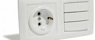
- The process of installing such an outlet is very simple; you just need to insert it into a regular outlet, like an adapter.
- It is this easy connection method that makes this type of smart plug so popular in the market.
- The design itself is provided with special indicators that show the state of the device and reactions to sent commands.
It is worth noting that such devices operate at certain frequencies, so it will not spoil the signal to other devices. The disadvantage of such a device is the limited signal; manufacturers can offer sockets with coverage of an area of 100 meters.
Design of remote controlled devices
It should be noted right away that the devices in question cannot be fully considered classic power sockets, which are equipped with an additional remote control unit.
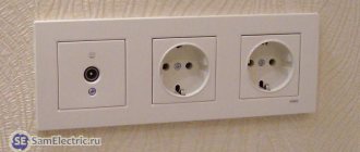
The remote-controlled models currently on the market are products that, in appearance, most closely resemble an adapter or socket with a timer. That is, they are equipped with a standard electrical “plug”, which is designed to plug a remotely controlled module into an ordinary plug socket.
The main purpose of this device is to open or close the power circuit to which the electrical appliance is connected. This allows you to control the operation of the consumer at a distance, without making any changes to its design or to the power supply network. In fact, the same function is performed by switches with remote control, of which there are quite a large number on the market. The main difference between these devices is that connecting the outlet is much simpler and does not require intervention in the wiring design. This makes it easy to move it from place to place, which is extremely convenient when working with some consumers.
Thus, a remotely controlled socket is essentially a switching device that, upon command from the control panel, opens or closes an electrical circuit.
Features of sockets with SIM cards
This device assumes the presence of a SIM card in the design, because control occurs using mobile phones. These sockets are provided with special indicators that indicate the presence of power, response to control and a special slot for a SIM card.
The advantage of this type is a large coverage area. You can control such a device within the coverage area of your mobile operator.
Some appliances may be equipped with blackout notification capabilities, which can help prevent short circuits and fires.
Also, these sockets may contain some additional devices, such as:
- Door opening and closing sensors.
- Temperature indicators.
- Indicators that inform about the humidity levels in the room.
- Timers.
- External microphones.
- Additional batteries that can operate without electricity.
The main disadvantage is the relatively high cost of such sockets.
Advantages and disadvantages
- Low cost compared to GSM and Wi-Fi electrical outlets.
- Possibility of manual control from the panel on the device body.
- High noise immunity.
- There is no need to redo the wiring for the radio adapter.
- Easy to connect. The device can be used in any convenient place where there is a standard plug connector.
- Concrete and brick walls are not an obstacle to the command radio signal.
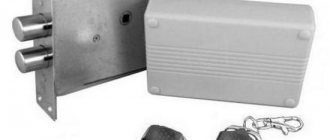
- Convenience of turning on or off household electrical appliances, controlling electromechanical locks, etc., which is especially important for people with disabilities.
- The ability to set operating modes for electrical appliances in models equipped with automatic on and off timers.
- Ability to control multiple devices from one remote control.
- Saving energy costs.
Features of sockets with Wi-Fi modules
Recently, this type of smart plugs has been in high demand in the market. This popularity is due to the fact that they can be equipped with additional means, such as:
- Various indicators.
- Timers.
- Microphones.
- Video cameras.
- A spare control method in the form of a SIM card.
This outlet can be controlled by any gadgets that have the function of connecting to a Wi-Fi network. This device is configured through special applications developed by the manufacturer.
The main advantage is that this outlet can be controlled from anywhere in the world. With the help of such devices, you can monitor the condition of the house, which significantly increases the safety of the premises.
Manufacturers of remote control devices
As in many areas of the modern market, the main manufacturers of such devices are Chinese companies. Since the use of remotely controlled sockets is not yet widespread, such eminent European manufacturers as Legrand or Scneider-electric, although they have similar devices in their model range, still rely on more traditional and popular technical solutions.
At the same time, technologies for the manufacture of electrical devices for household use are developing very quickly, so we can soon expect the appearance on the market of reliable, functional and inexpensive devices that allow not only remote, but also centralized control of the operation of all elements of electrical wiring.
Thus, the use of remotely controlled sockets can greatly simplify the operation of individual electricity consumers, as well as their groups. However, the installation of such devices should be approached with caution; their use is justified only in cases where manual switching on of electrical appliances is very difficult for some reason or there is a need to control their operation over significant distances.