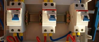
Areas of application
Triple switches are used to switch three groups of lighting fixtures.
It is possible to create combined lighting when both central and local light, multi-arm chandeliers, multi-level lamps in plasterboard ceilings, etc. are used. The advantages of tees include the following characteristics:
- economical energy consumption;
- small dimensions;
- attractive design;
- the ability to control lighting fixtures in different rooms from one place;
- the ability to use where the use of dimmers is not practical due to technical conditions;
- If desired, you can change the light intensity of the room.
Electricity savings are achieved as follows. For example, there is a six-lamp chandelier in the room, for which there is a single switch. When the lights are turned on, all six lamps are used, because there is simply no other option for supplying electricity. If the lighting fixtures are divided into zones, then after pressing one of the keys, two or three lamps will turn on, which may be quite enough for good illumination, and energy consumption will be lower.
So, the use of tees is justified when achieving the following goals:
- changes in the light intensity of one of the lighting fixtures;
- control from one place several light sources at once;
- control of individual lighting zones within one room.
Device: advantages and disadvantages
Until recently, the connection of various elements - sockets and switches - was carried out in a separate junction box, and then they were carried to those places that were determined by the project. Now savings come first: both time and effort. Paired designs make it possible to perform the operation much faster.
pros
Among the advantages of combined blocks:
- A simpler circuit, thanks to which there is no need to lay wires to each element.
- Fairly easy marking due to the larger block size.
- The fastest possible installation on walls.
- Minimum number of holes.
This is not to say that this solution does not have its drawbacks.
Minuses
These include:
- High price. Combined blocks, naturally, are more expensive than individual elements.
- Impracticality. If one component of the device fails, then more often the entire unit will have to be replaced.
- Increased load on wires. In this case, it is necessary to calculate their cross-section, otherwise the risk of overheating will be high. To connect a block device, it is recommended to take into account the maximum load.
- Location restrictions. The combined element can no longer be placed at the top of the wall, since in this case the appearance of the room will be spoiled by the plug and cable of an electrical appliance that is constantly needed. “Turning on the light” will not be very convenient, especially in the dark.
The biggest disadvantage is the need to replace the entire unit if one of the elements suddenly refuses to work. All other shortcomings can be accepted. But is the purchase of such an invention justified?
Serial and parallel connection
The daisy chain method is otherwise called serial connection of sockets. In contrast, the parallel connection method provides for powering each outlet with a separate line from the distribution box (for the most powerful devices, a line is drawn from the distribution board).
Advantage of daisy chain connection:
- less dirt and dust is formed: the groove is made in a short area between the sockets;
- for the same reason, labor costs are reduced;
- cable costs are reduced.
But there are also important disadvantages:
- low reliability: if the wire burns out, all subsequent sockets of the loop become inoperable;
- limited power: the maximum permissible current, determined by the cross-section of the cable cores of the first socket (at 2.5 sq. mm 16 A), is divided by all devices included in the loop (with a parallel connection, each socket can consume the maximum current);
- startup and shutdown of the device are accompanied by more noticeable voltage drops in adjacent sockets than with a parallel connection.
Principle of operation
Unlike a standard two-gang switch, the pass-through switch does not have an “on” and “off” position. Due to the different principle of operation of the mechanism, each key in it controls a changeover contact, that is, voltage is supplied to one outgoing contact and the power is simultaneously turned off from the other outgoing terminal. Two two-key devices control two different lamps/groups of luminaires from two different locations in the room.
The main feature of installing a pass-through switch with two keys is that one four-wire cable or two two-wire cables are laid between such switches. At the same time, it is enough to lay a two-core cable between single-key pass-through switches.
Connection diagram for pass-through switches
Pass-through switches are always used only in pairs, that is, there can only be two of them in the circuit, but not one or three. The connection diagram in the case of using two pass-through switches will look like this:
Classic lighting switching scheme from two points with pass-through switches
In practice, I usually use a VVG 3x1.5 cable, which has three wires - white, blue, yellow-green. See installation example below. So, in order not to get confused, I follow the rule: the input of the circuit (pin 1 SA1) is white, I connect the second and third contacts with blue and yellow, respectively, the output of the circuit (pin 1 SA2) is white. The light bulb is always connected to white (phase) and blue (zero) wires.
As can be seen from the diagram, the EL lamp will light only when switches SA1 and SA2 are in the same position - either upper or lower. When the positions are different, no current flows in the circuit.
Basic connection options
In old houses, all connections were made in a junction box under the ceiling. After it, the wires diverged each to its consumer. With the advent of blocks - various devices assembled in a single housing - it became possible to save on cables and cut less wires. In addition, there is no need to carefully measure the height of the socket with the switch in order to place them exactly next to each other.
The disadvantage of such combined devices is that if one thing fails, everything will need to be replaced together. It cannot be replaced separately.
Single-key option
This is the simplest version of the block design. All you need is the unit itself and a connected 3-wire cable. In the distribution box itself, it is necessary to make the wiring: phase, zero - to the socket, zero - to the lamp, another wire from the lamp - to the switch. Now you need to make the necessary connections inside the block itself.
As can be seen from the figure, connecting elements in one block is no different from separate ones. A phase and a neutral go to the socket. The same phase goes to the contact of the switch, then to the lamp. Now everything is inserted into the box, screwed on, and the key is put on. If you did it right, everything will work.
If the outlet is grounded, then the cable will not have 3, but 4 wires. The fourth is yellow-green. It goes to the ground contact. You can't connect it anywhere else!
Two-key block
There are situations when you need to turn on the light in the bathroom or toilet, and then you need to connect the washing machine somewhere. An outlet can only be installed in the bathroom itself if it has the necessary waterproofing. If not, then it is best to mount everything in the hallway. To save space and wires, we will again use the “all in one case” block, but only now with two keys. Connecting it is also not difficult.
Varieties
Sockets are classified depending on their design features:
- Closed and open models. The first ones are recommended for use in children's rooms. The second are classic sockets without closing curtains.
- Options with or without grounding. In the first case, the home owner will provide protection against voltage surges. The devices will be safe and sound.
- Overhead and hidden products. The first ones are installed to replace existing sockets, and the second ones are installed during renovation; their location is planned even when creating the project.
- There are also programmed models, polar or standard. Programmed devices turn on and off according to the set timer. But the simpler the design, the less functionality, the easier their installation. The choice of model directly depends on whether the installation will be done by yourself or with the help of a specialist.
Each type has its own marking, which allows you to choose the appropriate option. For example, “A” indicates that the device is made in the USA, but “B” confirms the presence of a grounding contact. The body of each socket is made of durable thermal plastic. From a decorative point of view, inserts are used; products are made in different colors.
Overhead 2-seater with grounding
The body of this model contains contacts that are necessary to protect electrical appliances.
Such an outlet also protects a person from possible penetration of current, which may accidentally end up on the plastic case. To install such an outlet, no additional renovations are required in the apartment; it can be installed instead of any conventional model.
Double pass-through with lid
The operating conditions of the device also determine its choice. The device case has a lockable lid, which protects the contacts from moisture. This product is marked IP-44. If the socket will be used outdoors, you should pay attention to the product marked P-55. The durable housing protects against moisture and dust.
Indoor installation
Indoor installation requires planning the placement of the device even during renovation work. In such options, the holes are hidden behind curtains, which are moved to the side when connected. Such sockets are grounded, because there may be children in the room. Only when pressed simultaneously, the curtains are activated. Even if you insert a foreign object into the socket, it will not work, so it does not pose any danger at all. This is why closed plan models are so popular among the varieties of double sockets.
Non-standard application
Some experts advise using a one-key switch with a socket instead of a standard socket - supplying the phase through a switch. This method is convenient for equipment without a shutdown button or quick de-energization of the equipment.
The disadvantage of the scheme is that it is compatible only with low-power consumers, which almost never happens in practice. None of the contacts are designed for high current, so the wiring heats up, melts and causes a fire.
The idea of combining a switch and socket appeared recently, but the devices quickly became popular for reasons of convenience and functionality. If the schemes are followed correctly, combined appliances will become an excellent interior solution, zone the space, and increase the number of power supply points.
Using a pass-through device instead of a conventional one
The marching switch can be used as a regular key switch. In this case, only two contacts are involved - one moving and one fixed.
Using a pass-through switch as a conventional device.
The second fixed contact is not connected anywhere. This circuit completely replaces a conventional device. In terms of dimensions, in most cases, they are also a complete coincidence. But a main switch is more expensive than a key switch, so such a replacement makes sense only when a simple key device is not at hand. The idea of making a special switch from a main switch is irrational from a financial point of view.
Kinds
Two-key switches are available in several versions:
- with backlit keys;
- combined with a socket;
- designed as a pass-through switch.
By design, switches are available for outdoor or indoor installation. Connecting a two-button light switch depends on the specific situation. It is necessary to decide where the switch for two chandeliers will be used and decide which option is needed.
There are options for two-gang switches that have four contacts instead of the standard three. They are two isolated single-key switches combined in one housing. They are called modular.
For indoor installation
This device is the most common. It is used in office and residential buildings. Installed in a mounting box, which is mounted in a plasterboard or concrete/brick wall. Due to the fact that the switch is hidden in the wall, it is also called “recessed”. The wires are supplied to it in special grooves called grooves. If the switch is fixed in a framed plasterboard wall, then the cable to the switch is laid in a corrugated pipe.
For outdoor installation
When installing open-type wiring, outdoor switches are used. They are mounted on a non-flammable base, and the wires are connected to them in cable ducts, metal hoses, corrugated plastic pipes or on top of the wall on porcelain insulators. Most often, the connection diagram for a two-button switch for two open-type light bulbs is used in wooden houses of gardening partnerships. Outdoor installation is also used in sheds, garages, basements and other utility rooms.
Socket - what is it
These elements of the electrical network are the “end point” on the line of transmission of electricity (signal) from the producer to the consumer (individual device or group). They differ in size, shape, color design and other parameters. The device is simple: base (ceramic or polymer heat-resistant), front panel (protective cover), spring contacts. The design and number of contacts depend on the specific application and characteristics of the electrical network (1 or 3 ph, without or with grounding). According to the current standard in the Russian Federation, household sockets have 2 holes (round): for L and 0.
Connection methods
The three-button switch can be connected using a junction box or without it.
With junction box
First of all, you will need to disassemble and remove the old switch from the wall, clean the niche and check the condition of the wiring. There should be five wires coming out of the wall. Now you need to turn off the power to the apartment, straighten the wires, and then direct power to them.
Using an indicator screwdriver or other device, paying attention to the color of the insulating material, find the single-core and neutral phase conductors and connect them to the socket. The phase is placed on the contact going to the jumper of the device. The remaining three wires are placed on their corresponding contacts. When you press the switch buttons, the lights should light up.
How to connect a socket and switch: diagrams and installation recommendations
You can replace switches and sockets yourself or hire specialists to do this work. If you lack knowledge and skills in handling the electrical network, it is better to give preference to the second option. In this case, the risk of short circuit is eliminated, and compliance with all safety rules and high-quality installation is guaranteed.
Note! If powerful electrical appliances such as a water heater are connected, grounding will be required. In this case, it is better to invite an electrician. The technician will select a cable with the optimal cross-section and correctly connect the wires to the outlet.
Connection diagram for socket with switch
List of necessary tools for installing the product yourself:
- drill core;
- drill;
- pliers;
- screwdrivers with insulated handles (2 pcs.);
- wire cutters
Preparation for installation involves choosing a location for installation, marking and drilling holes in the wall using a crown. If the wiring in the room is hidden, you will need to create a niche. The body part has perforated holes for cables. They should be broken out.
How to connect a socket and a switch from one two-wire wire
For a socket with a switch in one design, a certain sequence of installation actions is provided. The easiest way to solve the problem involves using a clear diagram for connecting the wires to the device in the distribution block.
Before carrying out work, it is imperative to turn off the power to the apartment or house.
How to connect a socket from a switch:
- Forming a hole for mounting an indoor unit or selecting the optimal location for installing an outdoor one.
- Determining the phase from the distribution panel and de-energizing the room.
- Phase supply to the switch. To do this, the ends of the phase conductors are stripped, twisted and covered with insulation.
- The neutral core of the network is connected to the socket and covered with insulation.
- Wires that are left unused are twisted together and covered with insulating material.
Using this diagram for connecting a socket and a switch by connecting the phase cable through a switch will be advisable if the power socket is used extremely rarely, and constant switching on and off of electrical appliances is required.
The operating principle of this design is extremely simple. If the switch is in the on position, a phase is supplied to the socket through the switch. This system is convenient in cases where there is a water heater installed in the room that does not have an off button. Due to the installation of the combined structure, you will not have to constantly pull the plug from the network.
Following safety rules, it is necessary to work with rubberized gloves.
How to connect a socket with a switch in one block
The switch and socket, combined in one design, can be operated separately from each other. For example, in a diagram for connecting a light bulb through a switch with a socket, cables with phase and neutral are laid from the main panel to the distributor box.
The box will contain several wires:
- Cables coming from the lamp (2 pcs.).
- Wires leading from the block (3 pcs.).
The phase conductor that comes from the shield is connected to the socket. The neutral conductor from the electrical network is connected to the neutral cable coming from the lamp and socket. In turn, the phase wires connecting the switch and the cartridge are twisted together and must be insulated. After this, the ground connection is connected using a suitable cable.
The process of connecting a socket with a switch in one housing
Helpful advice! To create a connection between the socket and the terminal located on the switch, it is advisable to use a jumper.
In this connection diagram for a single-key switch, the socket will operate independently of it. In this case, the process of turning off and on the light bulb of a lighting fixture in a room will not affect other elements of this design and affect their functioning.
How to connect a double switch and socket to the network
Most often, a two-key switch and socket are installed in a partition, in the area between the doors to the toilet and bathroom. Thanks to this, it becomes possible to control the lighting in two rooms and simultaneously connect any electrical appliances through an AC outlet.
Diagram of the distribution box and connection of a two-gang switch.
Five conductors are used for connection. They connect the twin structure and the junction box. During operation, you need to make sure that the neutral wire and the grounding conductor are connected to the outlet and only to it. Using a special jumper, you should apply a phase to a switch with two keys. This element is present in the switching block.
According to the double switch circuit, a pair of free wires is connected to its switching contacts. Through this element the phase will be supplied to the lighting fixtures located in the bathroom and toilet. In the distribution box, you should twist the wires of the free cores with those that supply the phase through the switch. Due to this, the system is connected to the light bulb sockets in the premises.
The ground and neutral wires are formed in the distributor box by connecting the bare ends with twists that were intended to connect the socket. If the need arises to replace the sequence of switch keys that supply voltage to the lighting fixtures in the bathroom and toilet, the cores on the switching contacts should be swapped.
Connection features
The connection diagram of the switch depends on its type.
The unit itself is connected in the same way as the option with two or one button. The power cable is connected to the input of the switch, and the wires are pulled to three light bulbs. The socket has its own zero, it is not connected to the switch, but they have a common phase. The neutral working wires (both from the socket and from the light bulbs) are directed to the distribution box, and the phase wire is led to the unifying contact at the input of the device. Lighting cables are placed on insulated blocks, from which the voltage is supplied to the lamps. The ends of the conductors are stripped of 1 cm of insulating material.
Switches are placed vertically on the wall, most often next to the door frame. You can construct a niche for the block with spacer elements and a frame frame. The switchgear is equipped with 5 connections, with the grounding going to the socket. For devices with metal elements, it is necessary to place a protective connection under the screw to protect against electric shock.
Connection diagram for a three-key switch with socket
Connection diagram for a three-key switch with a socket.
The diagram is often located in the instructions supplied with the device. For a triple switch, regardless of the presence or absence of an outlet, it has a standard appearance. Zero cables (3 pieces) from the lamps are connected to the zero, and one conductor is directed to the socket. In apartments of multi-storey buildings, only phase cables go from the wall, and neutral cables lead directly to the lighting device. If this rule is ignored, chandeliers and sconces will be energized all the time - then the resident is in danger of receiving an electric shock even when performing a simple procedure for replacing light bulbs. Models with a socket have an additional zero.
If there is no socket, 4 cables lead to the switch, and 5 if there is one.
In apartments with a Soviet-era layout, you can place a box with three keys only at the junction of the bathroom, hallway and kitchen. To install it in the bedroom or living room, you will need to partially change the placement of the wiring. It is better to invite a professional electrician to perform this work.
If you intend to connect all the switches yourself, in the living room of such a house you can install only a device with one or two buttons.
Installation errors
When connecting a three-key switch with a socket in the same housing, erroneous actions are possible, as a result of which the lighting devices may not turn on. Common cases include:
- A non-working switch with a working socket indicates that the technician has mixed up the phase and neutral wires. You need to check the design with an indicator and make the required changes.
- Two buttons do not function until the third is pressed - a sign that the phase was launched to the output of the third button, and not to the main input.
You should not connect a tee to the socket - its contacts are not designed for high voltage, and the device may stop functioning.
Manufacturing companies
Often the choice of a particular switch with a socket is determined by the attractiveness of the design. For example, the Spanish company produces antique-style models. German products are distinguished by modern, sophisticated design. French electrics are successfully integrated into the surrounding interior: both vertical and horizontal modifications are made. Perhaps the widest selection of products is presented. The product line of this Swiss company also includes products with LED backlighting.
Among Russian manufacturers, Kuntsevo-Electro can be distinguished. The company produces several models of three-key switches:
- BELLA BKVR-039 (there is a socket without a grounding contact);
- BELLA BKVR-212 (with indicator light);
- BELLA BKVR-036 (the model is equipped with a European socket and protective curtains).
Combined unit Bella BKVR-033 and BKVR-054
The specified switches operate in 220 V networks with a rated current of 10 A. Models are also produced in Russia for a rated current of 16 A with grounding. For example, NPO Elektrotekhnika produces models BZVRzk-S and BZVRzksh-S.