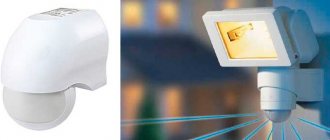
A photo relay, a light sensor, or as it is also called a day-night sensor, is necessary for automatically controlling lamps without your participation, depending on the light level.
It got dark outside and the lamp turned on by itself. In the morning at sunrise I switched off.
It can also be used to power advertising banners and signs on the facades of houses and shops.
Some people use time relays or timer sockets in this business. However, due to the constant change in the length of daylight hours, such devices will have to be constantly reconfigured.
Therefore, they cannot be considered a full-fledged alternative to light sensors.
Setting up the light sensor
In addition, the photo relay has its own sensitivity adjustment. You can manually set one or another trigger threshold.
That is, the flashlight will work in complete darkness at night, or in the evening, when it is just beginning to get dark.
On popular photo relay models from IEK FR-601 and FR-602, the regulator is located at the base and rotates in the range from “+” to “-”.
If you turn it to the maximum “+”, the photo relay will operate at dusk or in bad weather (cloudy sky). According to the technical characteristics, this adjustment corresponds to approximately 50 Lux.
If you move it to the extreme “-” position, the sensor will only work in complete darkness (illuminance 5 Lux).
It is usually set to the middle position.
These twisters are quite delicate and break easily if too much force is used. So be careful, especially when adjusting sensitivity in cold weather.
At the same time, pay attention to an important nuance.
Mistake #1
The photo relay should be configured outdoors, not indoors.
The sensor is always supplied with a black bag to check its functionality. They covered the device cap with it - the relay worked.
So, in many models, sensitive photocells located inside the case can react, in addition to illumination, to ultraviolet radiation from the sun's rays.
At home, due to glazing, 80% of UV rays are extinguished, but not on the street. Therefore, setting up at home with the creation of artificial darkening may differ from the real outdoor setting.
When there isn't enough range, some get creative and use foil for additional adjustment. The sensor is wrapped with it (fully or halfway), and thereby achieves an initially larger dimming value.
Connection and setup
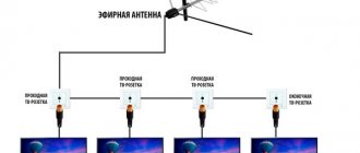
First you need to use a simple diagram for connecting a photo relay with a power unit and a street lamp. It is advisable to place the sensor in close proximity to the lighting device. Each product comes with instructions describing step-by-step installation and connection. In most cases, the relay is attached directly to a pole with a lantern to a height of no more than 3 m.
The presence of a remote sensor does not change the installation sequence. The relay is mounted in the right place so that the sun's rays fall on it, and no other objects come between the sun and the product. The unit is connected indoors next to the power supply. Ideally, you need to use devices that can independently adjust their performance characteristics. However, most models are equipped with conventional mechanical toggle switches that adjust the light sensitivity threshold.
The body of a quality product must have indicators that simplify the process of connecting and adjusting the device. When you rotate the toggle switch upward, the photo relay will operate faster and turn on the flashlight at dusk. If the toggle switch is turned in the other direction, the sensitivity threshold will decrease, which can lead to the light turning on only with the onset of complete darkness.
You can assemble the photo relay yourself, and it’s quite simple to do. In order for the product to be compact, it is necessary to exclude the use of large elements. You should not take an emitter follower assembly; it is best to construct it from two transistors to increase the input current.
Connect a low-power relay to the circuit, used as a transistor cascade. To eliminate the effects of reverse current, you need to use diodes that conduct electricity exclusively in one direction. The simple truth is that as the voltage increases, the product becomes more sensitive.
Direct connection diagram
A three-wire circuit is used to connect the light sensor. It means that you need to supply the device with full 220V (phase + zero), and not just phase.
Almost the same scheme is used for motion sensors. True, there are options for a two-wire connection without a zero.
Where to connect the phase and where to connect the zero? In this matter, you can be guided by colors.
Usually one of the wires should be blue or green - this is zero.
The other two conductors also differ in color. For example, one will be brown (black), the other will be red.
Brown is the input phase from the power supply. The third wire (red) is the output to the load. The phase appears on it only at the moment the photo relay is activated.
It just needs to be brought into the lamp.
The factory wires on the sensor are short, so they have to be lengthened. Prepare terminals or sleeves for pressing in advance.
The extension is made using a cable with a cross-section of 1.5 mm2. The general connection of all conductors must be carried out in a protective junction box.
This is what such a connection diagram will look like directly from the switch located in the switchboard.
Features of connecting wires
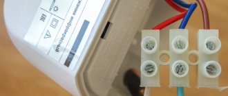
A photo relay from any manufacturer has three wires. One is red, another is blue (can be dark green) and the third can be any color, but usually black or brown. When connecting, remember:
- the red wire always goes to the lamps:
- the zero (neutral) from the power cable is connected to blue (green);
- a phase is supplied to black or brown.
If you look at all the diagrams above, you will see that they are drawn in compliance with these rules. That's it, no more difficulties. By connecting the wires this way (don’t forget that the neutral wire must also be connected to the lamp) you will get a working circuit.
Connection diagram via switch
If you want to install another intermediate single-key switch, so as not to run to the switchboard every time to turn off the light, then the connection diagram of the photo relay wires will change slightly:
There will be 4 cables going into the junction box. The power phase will be supplied through the following chain:
- machine in the switchboard
- light switch
- light sensor
- flashlight
How to set up a photo relay for street lighting
It is necessary to configure the light sensor after installation and connection to the network. To adjust the response limits, there is a small plastic rotary disk at the bottom of the case. Its rotation sets the sensitivity.
Find a similar regulator on the body - it adjusts the sensitivity of the photo relay
A little higher on the body there are arrows that indicate which direction to turn to increase and decrease the sensitivity of the photo relay (to the left - decrease, to the right - to increase).
To begin with, set the lowest sensitivity - push the regulator to the extreme right position. In the evening, when the lighting is such that you decide that you should turn on the light, you begin to adjust. You need to smoothly turn the control to the left until the light turns on. At this point we can assume that the setup of the photo relay for street lighting is complete.
Where to install?
Pay attention to the installation location of the photo relay.
Mistake #2
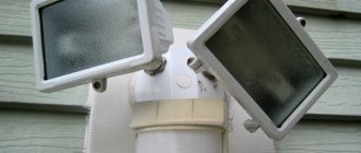
For any connection scheme, the sensor itself should not fall into the lighting area of the lamp.
Therefore, in 90% of cases, the photo relay is placed above the lantern.
If the body of the spotlight allows, you can even attach it directly to it.
Otherwise, the entire circuit will not work correctly and spontaneous operation and blinking are possible.
At the same time, the relay should not react to short-term flashes, for example, headlights from passing cars, thanks to the time delay set at the factory.
If there is no way to hide the sensor as far as possible from the lamp, then at least cover the housing on the lamp side with plywood or another opaque partition.
Incorrect operation is also possible after prolonged use. This is due to the fact that the cap of the photo relay gradually becomes dirty and darkens, allowing a different amount of sunlight to pass through it over time.
As a result, the response thresholds change dramatically. If it is just dirt and dust, then the problem can be easily solved by wet cleaning. But when the plastic turns black over time, only replacing the protective cap or the entire device will help.
Often the zener diode burns out in such relays. This is their main weak point.
Also, when choosing a photo relay, pay attention to the operating temperature. For example, the same FR-601 work well down to -25C, and then they start having problems.
In this case, a regular light switch will help you again. Only in the circuit it needs to be connected differently than discussed above.
The phase must pass through it directly to the lamp. This is a kind of jumper in case the sensor does not work or fails.
The light will turn on with the usual flick of a switch, just like all the light bulbs in your home.
Also in the passport data of such photo relays the degree of protection is indicated - IP44.
This means that the sensors can be safely used outdoors. They are protected from splashes and raindrops.
However, pay attention to the correct placement of the device.
Mistake #3
For example, some models can only be installed upside down!
They have a hole in the protective cap through which moisture can easily penetrate into the inside of the device.
Characteristics and features of choice
First you need to select the voltage at which the street light sensor will operate: 12 V or 220 V. Another important characteristic is the protection category. Due to the fact that the device will work outdoors, the protective class must be at least IP 44. That is, objects larger than one millimeter in size will not penetrate into such a device and they will not be afraid of splashes of water. The next selection criterion is permissible temperatures during operation.
It is recommended to choose light sensors for day/night street lighting that slightly exceed the average temperatures in your area.
to select a twilight sensor based on the power of the connected light bulbs and the electric current of the load. Here, too, it is better to take devices with a small margin.
Some devices provide the ability to adjust sensitivity. It is recommended to reduce this indicator when snow falls. In this situation, the light reflected from the snow surface may be perceived by the sensor as dawn. As a result, the lighting will constantly turn off and on.
The response delay is also considered a very useful option. For example, if at night the light from car headlights hits the photo relay. If the delay is very small, the light will turn off. But this will not happen if it is at least five to ten seconds.
The light sensor works in reverse
And if for some needs you need the relay to operate in reverse mode? It supplied voltage and turned on the load during the day and turned it off at night.
For example, for lighting in a barn with animals where there are no windows. What to do in this case?
Then go to the nearest store and buy an intermediate relay, in which one of the contacts closes and the other opens when triggered.
All you need to do is connect this intermediate relay after the light sensor according to the diagram below.
A starter with additional contacts can also act as such a relay.
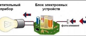
Device and principle of operation
A photo relay is also called a photocell or a light sensor; the device automatically turns on the light at dusk and turns off at dawn.
Photo relay for lighting control
Yandex.RTB RA-1479455-2
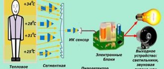
The operation of the device is based on the ability of some elements to change their parameters under the influence of sunlight. The most commonly used are photoresistors, phototransistors and photodiodes. In the evening, when the light decreases, the parameters of the photosensitive elements begin to change. When the changes reach a certain value, the relay contacts close, providing power to the connected load. At dawn, the changes go in the opposite direction, the contacts open, the light goes out.
Areas of use
The main purpose of the photo relays discussed in the article is to organize the automatic switching on of artificial lighting in the absence of natural lighting. But they also find application in other tasks;
- Irrigation of the lawn and watering of house plants. The device is connected to the irrigation system, and it starts working in the mornings or evenings, depending on the settings;
- connecting a light sensor is useful in creating a “smart home”. Such a sensor is an important element of the smart home ecosystem and provides periodic switching on and off of lights, automatic shut-off of water using a timer and other actions at the request of the owner;
- implementation of projects where equipment is required to execute a certain command when a set lighting threshold is reached - alarms, automatic meters, automated photo and video recording systems, and so on. Photo sensors are common on conveyors, where they are used to count manufactured products;
- automation of laboratory processes;
- control of room temperature or liquid heating level with a photo relay. When the mercury column of the thermometer reaches a certain point, it crosses the light beam incident on the photocell, triggering the relay to turn off the heating or turn on the fan;
- automatic school alarm notifying about changes. By closing the light holes made in certain places, the minute hand will trigger the bell;
- implementation of “smart” drinking fountains and water taps that open when you bring your hands to them (which block the light falling on the photosensor);
- livestock farming - imitation of the “day-night” regime in places where animals are kept;
Cost and best manufacturers
Motion sensor to turn on the light
The cost of a photo relay depends on the manufacturer, brand, design, degree of protection, warranty period, and equipment. The cost is affected by the quality of the case, its tightness and resistance to damage.
The price of models may vary from point of sale, but on average is:
Made in China, cost 269 rubles;
Photo relay FR-3E on Din-rail IP20
Manufactured by NTK Composite in St. Petersburg with a remote sensor on a wire 970 m long and a temperature difference from -40 to +40 degrees Celsius, cost 509 rubles.
Manufactured by Relays and Automation, Moscow, cost 3,386 rubles.
Ф1260700 LUNA
From the company Theben Germany with a built-in sensor, with an outside air temperature from -35 to 55 degrees Celsius, the cost is 4,580 rubles;
TWA-1 astronomer
From the Spanish manufacturer ABB with Din-rail mounting, with a 5-year battery and two modules. Cost 8,461 rubles.
Photo relay BJE2240W-53
Manufactured by ABB, with a built-in sensor, a large lighting range -30-500 lux, cost 11,250 rubles.
When purchasing, you need to choose a photo relay taking into account the technical characteristics, reliability and design features. For one light bulb with a power of 100 W, any model is suitable.
When connecting several lamps, you need to calculate the load current. To do this, you need to divide the power of all lamps by 220 W. The resulting figure must be compared with the load current of the device.
Devices with a remote sensor are more reliable, since the electronics operate in more comfortable conditions. But models with built-in sensors are much easier to install. Devices connected using terminals are much easier to install.
The most popular domestic and foreign manufacturers of photosensitive relays:
- Spanish companies: Legrand, ORBIS, ABB.
- Czech company ELKO EP.
- German manufacturer Theben.
- Belarusian enterprises Nootekhnika, Euroautomatika FiF.
- Domestic manufacturers: Relays and automation, Astro-UZO (Moscow), Meander, NTK Composite (St. Petersburg), AVAR (Pskov).
It is advisable to buy directly from manufacturers; you must also pay attention to the warranty period. https://www.youtube.com/embed/2_Q-NCuvhw8
Appearance of the motion sensor.
Light sensor to turn on the light.
device and application Sensor LXP-02.
Sensor output assignments:
1. Red is needed to supply the load
2. Blue, maybe green, is zero
3. Brown (black) - power sensor.
If you remove the white case, then under it we will see the sensor circuit located on the printed circuit board.
To easily calculate the required number of lamps, use the Calculator for calculating the number of lamps.
The sensor contains a DE3F-NA 24 VDC relay. Contact current 10A. This value determines the maximum load that the sensor is capable of. That is, 10 by 220 will be 2.2 kW. Exactly the same as stated in the instructions.
But my opinion: you should not connect more than 4 amperes to this sensor. Everything above is only possible through an intermediate starter.
Advantages of photo relay
Unlike contact-type control components, for example, electromechanical or induction relays, the described devices are distinguished by their durability. In addition, these devices based on field-effect transistors (the so-called MOSFET transistors) heat up less, and therefore can be used in long-term operating control circuits, for example, in photo relays for street lighting.
Metal Oxide Field Gate Transistor
The use of MOS transistors as a signal output device allows them to be used in solid-state relay circuits that operate on both alternating and direct current.
Subsequent comparison of the effectiveness of the product with other types of tracking devices for similar purposes can be performed using the following parameters:
- Minimum installation space required (less than relays with moving parts).
- Reliability (higher, since there are no moving contacts that wear out due to friction and electrical erosion).
- Energy consumption (less due to the absence of auxiliary components; battery-powered operation is possible).
- The switching intensity does not depend on the number of switchings, because there is no need for transmitting devices.
Photo relays are also advantageously characterized by the absence of noise during operation, high speed of switching control modes, and the absence of audible clicks during operation.
The compactness of a typical photo relay circuit for street lighting is illustrated in the figure: