What is a pass-through switch used for?
The main feature of a pass-through switch is the ability to turn on the light in one place, go to another and turn off the light there.
So conveniently and comfortably, any number of people can move in any direction and sequence. That is why the device is called a pass-through device. In practice, this is very convenient to go through, for example:
- from the garage to the house down the street;
- follow the long corridor;
- climb the stairs from the first floor to the second;
- turn on the light at the bedroom door, walk to the bed and turn it off.
In all four cases, a pair of pass-through switches will help us out. The convenience of using such devices in large apartments and houses is especially noticeable. To control lighting in more complex combinations with several lamps and control points, pass-through switches with different numbers of keys and internal circuits are used.
Where is the device placed?
As a rule, pass-through switches are installed in different zones to make them convenient to use. It is not necessary to use two switches. So, one of them can become the main one, and the other auxiliary.
If the electrical wiring was located in a corrugated tube, then when installing a pass-through device, it will be possible to perform the replacement without gating the ceilings.
Electrical wiring in a corrugated tube
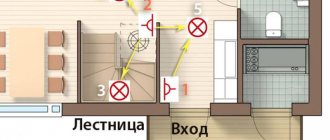
Most often, standard pass-through switches with one or two keys are placed at the following points:
- On both sides of a narrow corridor. If there is a door in the center, then you can also install the device near it.
- In spacious bedrooms. So, according to the standard, one switch can be installed at a distance of 30-40 centimeters from the door frame, and the other above the bed.
- On the landing.
- Along the path in the courtyard of a private house. After all, it will be convenient to go for a walk in the evening, and if necessary, turn on and off the lights along the way.
- In the halls of a large area, where there are several entrances on the sides.
Using a pass-through switch is advisable not only to save electricity, but is also necessary for the safety of movement. It turns out that the only drawback is the difficulty of installation for some masters.
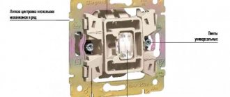
Pass-through type switch design
Externally, a main switch is no different from a regular switch, except for the presence on the key of a conventional image in the form of two triangles and a diagram of the device on the back side of the dielectric base.
Inside the pass-through switch there are three contacts: two fixed and one movable (changeover), driven by the external key of the device. The changeover contact has two possible operating positions - on one of the fixed terminals. By pressing a key, the movable contact moves from one terminal to another, breaking one circuit and closing the second.
This design feature of the pass-through switch is the basis for a network design in which one lighting fixture can be controlled from two different locations. The neutral and grounding wires from the distribution box are connected to the lighting device, and a break is made in the phase conductor with two pass-through switches, between which two alternative lines are laid.
Connection features
You need to connect two wires to the output of the device - the jumper, which is included in the design, alternately closes the electrical circuit. These cables connected to the output are connected to the second switch, but with one wire going directly to the lighting fixture. Consequently, a pass-through switch simply allows the transfer of electricity from one line to another.
Today you can find triple pass-through type switches on sale. Of course, due to the complexity of the design, its cost is simply prohibitive. It is unlikely that anyone will want to overpay for such a device if it can be made from simple ones. Moreover, you do not need to have seven spans in your forehead, special tools and diagnostic equipment. The manufacturing work is not complicated and can be completed strictly according to the instructions given below.
Operating principle of a pass-through switch
Unlike the usual models of two- and one-key switches for turning on lighting, pass-through switches provide two on positions. To operate the circuit, two pass-through switches are used, with which you operate the lighting lamps.
A schematic diagram of the operation of such an electrical circuit is shown in the figure below:
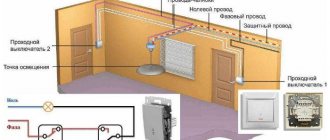
Figure 1: operating principle of a pass-through switch
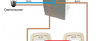
As you can see, in the diagram, the phase wire is connected from the electrical wiring to the switches, and the neutral wire is led directly to the lamp or other lighting equipment. If you trace the connection from the distribution box, the phase is supplied to the input of the first pass-through switch. Next, two independent wires connect the terminals A and B of the first device to the terminals of the same name of the second switch. From the output terminal of the second switch, the phase is supplied to the lamp output. The second terminal of the lamp is connected by the neutral wire.
Of course, the above connection diagram requires additional cable costs to connect the switches to each other, but its functionality more than justifies it. Due to its design features, such a switch does not break the circuit in any position, so it is more correct to call it a switch.
In everyday life, due to the use of such switches on staircase landings to disconnect flights from different points, they are also called marching switches.
If you decide to implement such a scheme at home or in the office, but do not want to overpay for a pass-through switch, it can also be made from a cheaper two-key device. Next, we will look at two techniques that will allow you to make a pass-through switch with your own hands.
DIY marching switch
The prevalence of self-manufacturing of pass-through switches is due to the fact that they are much more expensive than conventional ones, and are not available for sale in every household electrical equipment store. The most common method of manufacturing marching switches is to assemble them yourself from ordinary devices - single-key and two-key in various combinations.
Interesting read: what are capacitors?
Pass-through switch - from a conventional single-key switch
To control one lighting device (without dividing the lamps in it into groups), a single-key main switch is used. Unlike the model for hidden wiring, a pass-through device for outdoor installation can be difficult to find on sale, so it is the surface-mounted marching switches that are most often assembled independently.
It will be interesting➡ The best ways to check the Hall sensor
A pass-through single-key switch for external wiring can be assembled from two ordinary ones - also single-key. In this case, it is necessary that the switches are of the same model, and the arrangement of internal components in the housing is symmetrical. As a rule, products from one manufacturer are used for assembly. A proven option are switches from Schneider Electric, on one of which we will consider this operation.
Using a screwdriver with a narrow blade, the key is pryed up and removed from the housing, after which the dielectric base is pushed out of the switch by pressing on the front part. The extruded base is separated from the standard plastic socket box. Using the same screwdriver, 4 latches around the perimeter are snapped off, and the base is divided into two parts, each of which is symmetrical about the vertical axis.
Connecting a pass-through switch.
All the operations described are carried out with the second switch, but only in order to remove the rocker arm from it - metal contacts and a graphite rod. The removed rocker arm is turned over around its longitudinal axis and installed in the base of the first switch - in ready-made grooves next to the existing contacts, but in the opposite direction.
A second rod is also inserted into the paired socket, after which the dielectric base is assembled - a jumper (common contact) is installed between the two contacts on one side, the two halves are folded and snapped into place. Upon completion of assembly, it is necessary to “ring” the pass-through switch with a tester at different positions of the key. Accordingly, this device is paired with another one – also from two ordinary single-key devices.
How to use a pass-through switch.
Main switch - from a regular two-key switch
For this method of manufacturing a pass-through switch, you will need one two-key switch. Assembling a main product for hidden wiring is most easily accomplished by reworking products from the Anam, Legrand or Panasonic brands, which have a modular design. To remake the switch, the keys are removed from it, after which access to the modules mounted on guides in the housing appears. One of the modules needs to be removed and, turning it upside down, again installed in its original place.
The fit of the module must be pinpointed with drops of hot-melt adhesive, since in this position its latches may not coincide with the standard grooves. The switch is assembled in the reverse order and a device is obtained, the modules of which, after turning one of them, turn out to be working in antiphase. Therefore, on the back side of the switch it is necessary to install a jumper between the contacts on one side - it will be the common contact of the device. The two keys that are in place must be firmly connected to each other, for example, by filling the gap between them with a sealant of a suitable color.
Material on the topic: what is an electrical circuit.
Pass-through two-key switch
A two-key main switch is designed to control from several places two groups of lamps of a lighting fixture, for example, tiers of a chandelier. Pressing one key on the switch will supply power to one group (tier), and the second to the other. The product consists of two single-key pass-through switches mounted in one housing. Each key has one input and two outputs, for a total of 6 contacts per switch in total.
Thus, single-key and two-key pass-through switches have a common operating principle, but connecting a dual device is more complicated - the phase is supplied to both inputs of the first two-key switch, which is connected to the second by four conductors. To avoid mistakes, it is better to study the methods of connecting two-key marching switches using diagrams, here is one of them:
Pass-through two-key switch
Assembling and installing a two-key main switch with your own hands is only possible when using two converted devices mounted on the wall next to each other and connected accordingly.
It will be interesting➡ How to make a flashing LED?
To control two groups of chandelier arms from two different places, you will need four converted switches. The cost of conventional devices for assembling two-key switches in this case will exceed the price of a finished switch from the manufacturer.
The finished product outperforms the one assembled from two converted ones in terms of compactness and aesthetics, which is why they very rarely resort to self-assembly of pass-through two-key switches.
Differences between pass-through and traditional switch
The difference between a pass-through and a regular switch (rear view)
The switches are no different in appearance. The internal structure of a conventional one is equipped with one input and output. Can have up to three keys, allowing you to control multiple lighting sources. Most often they are installed near the entrance to the room. The connection is made using two terminals.
A classic checkpoint has two exits and one entrance. In this case, the electric current is not interrupted, but is redirected to any other output. There is a diagram underneath the product body. The single-key pass-through is equipped with three-wire switching and three terminals with copper contacts. This is a switch that redirects the current to other areas.
By design, installation method and type of control, switches can be:
- keyboards;
- push-button;
- sliders;
- traction;
- toggle switches.
They are also classified depending on voltage and current, degree of protection, and climatic conditions in which they are installed.
It is important not to confuse an electrical appliance with a changeover or crossover device. On the pass key there is a vertical triangle, in the rest it is located in the horizontal direction.
Self-production of a pass-through switch
Marching switches are available and easy to purchase. But in some cases it may be necessary to make a pass-through switch from a regular one. The easiest way is to use two key single-key devices.
Connection of two single switches.
The input terminals must be connected with an external conductor. The first disadvantage of this method is that you will have to manipulate two keys, each time they will have to be set in the opposite direction. Secondly, you will need to equip two places for installing electrical appliances. You can get rid of the second by using a two-key switch. But to turn the light on and off, you need to place both keys in opposite positions.
Scheme of operation of a two-key player as a changeover contact group.
It is easiest to completely convert a regular double switch into a marching switch if the contacts have a separate input. To finalize it, you need to get to the contact groups and turn over one moving contact.
Rearranging the contact of a double switch with separate contact groups.
But most two-keyboards have a different design - with a combined input. In this case, modification is more difficult.
Extended bus of a two-key device.
Simply turning over the changeover contact will not work - the long bus gets in the way. It will have to be cut (you can use metal scissors, etc.). To do this, you need to remove the entire contact system.
Cutting line.
After this, you need to turn the moving contact 180 degrees. Since the contact pad will now be on the other side, the fixed contact will also need to be rearranged.
Rearranging switch parts.
After this, you can assemble the contact system, install it in place and completely assemble the device.
Assembled contact system.
Devices from different manufacturers may have different designs, limited only by the flight of engineering thought. For switches from other manufacturers, alteration may be carried out in a different way (instead of cutting the busbar, it may be necessary to extend it, etc.). In each case, you need to look locally.
After this, you need to mechanically combine the two keys. This can be done using glue. If there is a suitable single-key donor, you can get a single key from it. You will get a full-fledged marching switch.
Diagram of the resulting pass-through switch.
Reworking the device
The process of converting a simple switch into a walk-through is accessible to everyone with their own hands. Its appearance is no different from its brother. It can have 1 key, 2 or more. The difference between these devices is visible only from the inside. The pass-through serves to switch circuits, so it is more correct to call it a switch. Most often at home you have to use a regular single-key main switch. In large rooms, a device with several keys is sometimes required.
The modification consists of adding a contact: instead of 2 you need to put 3. How to connect a pass-through switch to the network? A three-core cable must be laid between a pair of devices. The phase always goes to the switch, zero to the light fixture. Nowadays, photo relay circuits are made using KT315B transistors or Q6004LT. Our task is to make a pass-through switch from an ordinary marching switch with our own hands.
Sequence of work
And now we are starting to carry out work on remaking a regular switch in the entrance hall. To do this you need to perform the following manipulations:
- First, loosen the clamps to connect the appropriate cable. Be sure to loosen the socket box spacers. This is necessary in order to safely remove the switch from the hole in the wall.
- As you understand, in this case it is necessary to completely turn off the electricity in the house. Using a probe, before turning off the power, determine which wire the phase is on. Be sure to make marks on the wire. In this case, you will make installation of the device as easy as possible.
- Remove the switch and turn it over with the inside facing up. After this, unbend the clamps on the housing and remove the entire electrical part of the structure. Using a simple screwdriver, you can do this in a couple of minutes.
- Then, using a thick flat screwdriver, you need to remove the springs that are located inside the case. It is not recommended to use a thin screwdriver, as it is unlikely that you will be able to remove the springs. Be careful, try not to rush, so as not to bend or break structural elements.
- Using a flat-head screwdriver, pry off two teeth at the ends of the removed part of the switch.
Connection diagram of switches for controlling one light source from several places
To be able to control the lighting circuits, we need the following materials:
- distribution box with a diameter of 80 mm;
- 2 pieces of pass-through switches;
- flexible cable type PVSng or VVGng 3x1.5;
- 5 pcs of WAGO type terminal clamps for 2–3 contacts (or a soldering iron with tin and rosin);
- 2 pcs socket boxes for concrete (plasterboard).
The connection diagram for a pass-through switch made from the above materials will be as follows:
As we see in the above photo, to control lighting using pass-through switches, the neutral power wire in the terminal box is connected to the first output of lamps No. 1 and No. 2. The phase wire of the supply circuit in the distribution box is connected to terminal No. 1 of pass-through switch No. 1. The remaining two outputs of switch No. 1 are connected in the box to terminals No. 2 and No. 3 of switch No. 2, respectively. Next, pin No. 1 must be connected to the second free end of the lighting lamps.
The above circuit will allow you to fully control the lighting system, however, the above circuit does not protect a person from electric shock. For these purposes, the following connection diagram for the pass-through switch is used:
As we can see from the above photo, the main difference between the two schemes is the use of a three-core cable, which, in addition to phase and neutral, also contains a third grounding conductor. It allows, if the insulation in equipment or cable and wire products is damaged, to divert the resulting potential to the ground loop and cause the circuit breaker to trip.
Types of switches
Pass-through switches are produced as a separate type - they can have one/two/three keys for control. But if you don’t want to spend money, you can always convert a regular device to it. In fact, everything depends only on the wiring. In apartments they usually use a classic switch with one key. If you decide to create a pass-through switch from a regular one in a large room, especially if there are several light sources in it, then you can choose devices with two or three power buttons.
The main difference between the pass-through block and a conventional one is the presence of three contacts and operation from a three-core wire. Take this into account when creating the wiring. When connecting, make sure that the phase opens and the zero goes to the light bulb. In this case, you will not be shocked when replacing it or during repairs.
The diagram looks like this:
- Zero from the box is supplied to the lamp.
- Through the switch, the phase goes to the input.
- There are two cables to the output, both go to the second switch.
- From the second switch there is a cable to the lamp.
In fact, there is nothing difficult in creating a diagram. Anyone can quickly figure it out by looking at the picture.
How does a pass-through switch work?
Connection diagram for a pass-through switch with 2 places
The circuit of a pass-through switch from two places is carried out using two pass-through single-key devices that work only in pairs. Each of them has one contact at the entry point, and a pair at the exit point.
Before connecting the pass-through switch, the connection diagram clearly displays all the stages; you should de-energize the room using the appropriate switch located in the control panel. After which it is necessary to additionally check that there is no voltage in all wires of the switch. To do this, use a special screwdriver.
Helpful advice! A similar check must be performed at the installation sites of switching devices.
To complete the work you will need: flat-head, Phillips and indicator screwdrivers, a knife, side cutters, a level, a tape measure and a hammer drill. To install switches and lay wires in the walls of the room, appropriate holes and grooves must be made in accordance with the device layout plan.
Unlike conventional switches, pass-through switches have not two, but three contacts and can switch the “phase” from the first contact to the second or third
Wires must be laid at a distance of at least 15 cm from the ceiling. They can be placed not only in a hidden way, but also placed in trays or boxes. This installation makes it possible to quickly carry out repair work in case of cable damage. The ends of the wires must be inserted into installation boxes, in which all connections are also made using contactors.
Connection diagram to the distribution box
Of particular interest is the connection diagram for the backup switch in the distribution box. We partially touched on this issue above.
Let's take a closer look.
It includes four three-wire wires:
- with AV lighting switchboard;
- to the first switch;
- to the second switch;
- to the light source.
When connecting wires you need to look at the color. When using a VVG cable, the following markings are used:
- White - phase.
- Blue - zero.
- Yellow-green - earthy.
A second type of marking is also possible - white, brown and black, respectively.
When assembling, proceed as follows:
- Connect the neutral cable of the input AB and the neutral wire that goes to the lamp at one point using vago terminals.
- Combine the grounding conductors (if provided).
- Connect the yellow-green wire to the lamp body.
- Connect the phase wires. To do this, combine the phase from the input with the phase of the terminal of the first pass-through.
- Using a separate clamp, connect the common wire of the second connector with the phase of the wire going to the lighting device.
After completing the steps above, connect the secondary (outgoing) wires to the first and second switch.
In this case, the principle of unification does not matter. Even if there is an error in the color designation, the diagram will work correctly. After this, you can apply voltage and check the serviceability of the circuit.
When using this connection, remember a few points:
- Make sure that the phase goes to the common wire of the 1st switch.
- The same phase wire should leave the common wire of the 2nd switching device towards the lamp.
- The other two conductors are combined with each other in a junction box.
- The neutral and ground wires are fed directly to the lamps.
Changeover switches - lighting control circuit from 3 places
But what if you want to control one lighting from three or more points. That is, there will be 3, 4, etc. switches in the circuit. It would seem that you need to take another pass-through switch and that’s it.
However, a switch with three terminals will no longer work here. Since there will be four connected wires in the junction box.
Here a changeover switch, or as it is also called a cross, cross, or intermediate switch, will come to your aid. Its key difference is that it has four exits - two from below and two from above.
And it is installed precisely in the gap between two passageways. Find in the junction box two secondary (not main) wires from the first and second pass-through switch.
Toggle switch option with hidden mechanism
Reversing switches are used in public spaces of large area and those that have opposite exits (in passage galleries, tunnels, corridors). In most cases, pass-through switches are installed in their usual place at the entrance and exit. In the apartment, switches are placed in a convenient place, for example, one is at the entrance to the bedroom, and the second is located near the bed.
An internal switch is installed if hidden wiring is installed in the walls along pre-made grooves. A corrugated hose is placed over the wires. A mounting hole is drilled into the thickness of the wall for the switch using a crown. The box body is secured using plaster or self-tapping screws.
The box for installing a pass-through type switch is spacious, since it contains bundles of wires and cables to other devices and lamps. After laying the wire from the distribution board, the wires are connected to the contacts of the switch according to the developed diagram.
The lamp contacts are connected to the neutral wire. The phase is connected to one of the supply voltages. The contacts are connected in series through a junction box in the room, after which they are routed to all lighting fixtures. For ease of operation, cables are marked or products of different colors are immediately used.
Disadvantages of pass-through devices
You should always check the circuit before connecting. The input and output contacts of the changeover switch can be located differently
The position of the keys does not allow you to determine whether the system is turned off or on. For example, it may not be possible to immediately understand whether the lights are turned off or a light bulb has burned out. It is impossible to control a lighting device from different places at the same time. A large number of connected devices means a lot of twists in the junction box. Connection errors force you to reassemble the entire circuit.
The pass-through switch has many functionalities. But to connect it, you need to purchase another device. The number of connecting wires also increases, which increases the overall cost of the system. An ordinary switch has a relatively low price, but loses in functionality.
The difference between a simple switch and a pass-through switch
A simple switch differs from a walk-through switch in that the latter has three electrical contacts with a switching mechanism located between them. In addition to the main convenience - the ability to turn off lights from points at different distances, the use of such a switch allows you to significantly save energy, and this is a definite plus. A three-core wire is laid in the groove or outside between the switches. When connecting two-key pass-through switches, there must be two such wires. Few apartments have such wiring, so to equip a house with such a switch, you need to lay the wire at the stage of repair work, or re-drill the wall for three-core cables. All types of lamps can be used as light sources - from LED to incandescent lamps. In addition to lamps, this scheme can also be used to connect other electrical appliances that need to be controlled from different places, for example, a boiler.
Types of pass-through switches
- Single-key (with or without backlight)
- Two-key (with or without backlight)
- Three-key
- Intermediate
- Overhead
- Built-in
These mechanisms have two disadvantages:
- It is impossible to determine from the buttons what position the device is in.
- The light does not turn on at several points at the same time.
Connection errors
Many people make a mistake at the stage of searching and connecting the common terminal in the pass-through switch. Without checking the circuit, they naively believe that the common terminal is the one with only one contact. They assemble a circuit in this way, and then for some reason the switches do not work correctly (they depend on each other).
Remember that on different switches the common contact can be anywhere!
And it is best to call it, what is called “live”, with a tester or an indicator screwdriver.
Most often, this problem is encountered when installing or replacing pass-through switches from different companies. If everything worked before, but after replacing one circuit the circuit stopped working, it means the wires were mixed up.
But there may also be an option that the new switch is not pass-through at all. Also remember that the lighting inside the product cannot in any way affect the switching principle itself.
Another common mistake is incorrectly connecting crossovers. When both wires are placed from pass-through No. 1 to the upper contacts, and from No. 2 to the lower ones. Meanwhile, the cross switch has a completely different circuit and switching mechanism. And you need to connect the wires crosswise.
What mistakes can be made?
Naturally, if you are unable to read the installation diagram for Lezard two-key pass-through switches, you can make a lot of mistakes.
And the very first one happens when searching for a common contact. By mistake, some people think that the common terminal is the one that is located separately from the other two. And this is not true at all. Of course, such a “trick” can work on some models, but this happens quite rarely. And if you assemble a circuit with an error, the switches will not be able to work correctly, no matter how many times you click them
The common contact can be located anywhere, so it is important to find it based on the diagram or readings of the device. Quite often, such problems arise when installing or replacing pass-through switches from different manufacturers. We looked at the information on one, connected it correctly, but the second one turned out to be from a different manufacturer
And they connected it according to the same scheme, but it does not work. To restore functionality, you need to find a common contact and connect all the wires correctly. This step is the main one; how the entire system will work in the future directly depends on it. There is no need to rely on chance; it is better to make sure several times whether the contacts are correctly identified. And so as not to forget, you can mark them with a marker. In this way, of course, so that these marks are not visible from the outside
We looked at the information on one, connected it correctly, but the second one turned out to be from a different manufacturer. And they connected it according to the same scheme, but it does not work. To restore functionality, you need to find a common contact and connect all the wires correctly. This step is the main one; how the entire system will work in the future directly depends on it. There is no need to rely on chance; it is better to make sure several times whether the contacts are correctly identified. And so as not to forget, you can mark them with a marker. In this way, of course, so that these marks are not visible from the outside.
But it also happens that the device you are using is not pass-through
Therefore, when purchasing, you need to pay attention to what type of device – pass-through or regular two-key. It is also worth mentioning the incorrect connection of crossover devices. Some electricians place the wires from the first switch on the contacts located at the top
And from the second switch - to the contacts that are below. But you need to do it a little differently - connect all the wires to the device crosswise. Only in this case will the entire structure be able to function correctly.
Some electricians place the wires from the first switch on the contacts located at the top. And from the second switch - to the contacts that are below. But you need to do it a little differently - connect all the wires to the device crosswise. Only in this case will the entire structure be able to function correctly.
Lighting control from three places or more
There are often situations when in large residential premises there is a need to control lighting from several points at once. To create a multi-point control system that allows you to turn on and off lights from 3 places at the same time, installing pass-through switches alone is usually not enough.
For these purposes, it will be necessary to integrate one more element into the circuit - a crossover switch, which is connected at the break of the two-core wire (that is, between the pass-through devices).
If in earlier times the permissibility of installing such schemes was determined mainly by the layout of the premises, today they are found almost everywhere. Installing pass-through switches of this type is not an easy task. First of all, you need to familiarize yourself with the principle of its operation.
Operating principle of a cross switch (switch)
The design of the switch provides for the presence of four contacts, of which two are connected to the terminals of one switch and two more to the second device.
When switched on in this way, these devices perform special (transit) functions, since they are to a certain extent transitional.
You can clearly see the principle of operation of the cross switch in the GIF picture below.
Connection diagram for three switches
A schematic diagram of connecting a 2-way switch and one crossover switch is shown in the figure.
It clearly shows that a cross switch is installed between the two pass-through switches, acting as a kind of transit node.
Below we provide a diagram of the connection of all elements of the electrical lighting control chain in the junction box.
The video that we have posted below will undoubtedly help you assemble a wiring diagram for three switches in a junction box.
Connection diagram for four switches
For four control points, you will need to use the complex wiring diagram shown in the figure below. This kit uses not only two pass-through switches, but also a pair of cross-type switches.
When considering the option of controlling a lamp from 4 places at once, two cross switching devices will be required.
If there are several lighting groups in a given room, preference should be given to two-key cross-type switches. Passage systems installed in this way significantly simplify the lighting control procedure.
These systems of many switched devices (for all their apparent convenience) raise doubts about their reliability to an even greater extent. Even if they are turned on correctly and handled with care, they are characterized by the following disadvantages:
- relatively high cost;
- relatively low reliability;
- possibility of false positives;
- difficulty of maintenance and repair.
That is why connecting pass-through and cross switches to control lighting from several places is the best option for using the principle of multipoint control.
Types of switches
According to their design, cross switches are divided into 2 types: key and rotary.
Keyboards
Switches of this type are most often used.
Key switches, or more correctly called switches, break one circuit and close another. Conventional switches only open or close one circuit. Externally, they are practically the same. They can only be distinguished from the back by the number of contacts:
- a regular single-key has 2 contacts;
- at the passer -3;
- the cross one has 4.
Differences between regular, pass-through and cross single-key switches (photo gallery)
A single-key pass-through switch has 3 contacts
A conventional single-key switch has 2 contacts. A single-key cross switch has 4 contacts.
Key switches can have 1, 2 or 3 keys. Multi-key switches are designed to control multiple circuits independently.
Rotary cross
Switches of this type are installed less frequently than keyboard switches. They are usually used in warehouses and industrial premises, for street lighting, and as interior decoration in apartments. The contact groups in them are closed and opened by turning the lever.
Appearance of rotary switches (photo gallery)
Used in warehouses
Used as interior decoration
Used in residential areas
Controls 2 circuits
Used in rooms with high humidity and for street lighting
Overhead and built-in
According to the installation method, switches are divided into 2 types: overhead and built-in.
Built-in switches are installed during the construction or renovation stage in boxes installed in niches. The wires are laid in grooves or attached to the walls. Typically, this method is used before plastering walls or covering them with plasterboard or other materials.
Surface-mounted switches and their associated wires are attached to the wall. In this case, there is no need to scratch the walls and knock out recesses for the boxes. They are usually installed in this way during cosmetic renovations. Overhead switches create certain inconveniences: dust accumulates on them, people cling to them while moving. In some cases, owners, on the contrary, prefer this type of switches for interior design.
Characteristics of cross switches
The electrical products market has a wide selection of switches and switches from domestic and foreign manufacturers. The difference in price between different manufacturers is significant, but the dimensions and technical characteristics are similar.
Main characteristics
| Voltage | 220–230 V |
| Current strength | 10 A |
| Housing material | thermoplastic polycarbonate plastic |
Models with housings that protect against moisture and steam are more expensive.
Pay attention to the article with instructions for connecting a three-key switch:.
Installation diagram of several switches
We have discussed the method of installing switches in the presence of one or two or three groups of lighting fixtures. After all, only two switches were required, which were located along a common line.
Now we need to consider a situation where there are several switches at different points. The bottom line is that they all need to control the same light fixture.
If it is necessary to organize control of a lighting device from three or more places, it will not be possible to use another switch other than a cross switch. Here one chain is incoming.
Here one chain is incoming
The switches, which are located on both sides, are connected according to the standard scheme. Only between them is another one, which has four clamps for connecting wires. After pressing one of the keys in this system, the connected contacts open and a cross-circuit occurs in a new circuit.
Of course, in addition to standard single-key devices, multi-key crossover switches are often used. This connection is required if there are several groups of lamps. However, here too you will have to make more connections using clamps. In addition, an inexperienced craftsman can easily confuse the wires, so care should be taken.
If it is necessary to install an additional point for “closing-opening”, then another crossover switch is installed with wiring connected to the already installed device.
Crossover switch
Craftsmen recommend making electrical wiring connections by passing conductors into the junction box. However, some people may find it easier to bypass the box using a wire and two strands.
As has been observed in practice, this is a rational connection method that does not violate safety regulations. In addition, such a connection allows you to reduce the cost of purchasing additional wires.
Common connection errors
Video - Connecting a pass-through switch
Despite the fact that the process of installing a crossover switch seems simple, you must follow the exact instructions to avoid mistakes. Otherwise, such a device simplifies the process of controlling the lamp - you only have to select a switch in accordance with the rules.
Using a Push Button Switch
There is another option - the pass-through switch is replaced with a push-button one, but designed for light loads. Having carefully calculated the system design, they buy two ON-ON switches, they should work like this:
- when the first group is on, the second is off;
- if the second one turns on, then the first one is de-energized.
When using such a pair, you can easily create a system of pass-through light switches.
It is not necessary to use the push-button version directly; any pair of switches of a similar system, including toggle switches, will do.