Code marking, addition
According to IEC standards, in practice there are four ways to encode the nominal capacity.
A. 3-digit marking
The first two digits indicate the capacitance value in pygofarads (pf), the last one indicates the number of zeros. When the capacitor has a capacitance of less than 10 pF, the last digit may be "9". For capacitances less than 1.0 pF, the first digit is “0”. The letter R is used as a decimal point. For example, code 010 is 1.0 pF, code 0R5 is 0.5 pF.
| Code | Capacitance [pF] | Capacitance [nF] | Capacitance [µF] |
| 109 | 1,0 | 0,001 | 0,000001 |
| 159 | 1,5 | 0,0015 | 0,000001 |
| 229 | 2,2 | 0,0022 | 0,000001 |
| 339 | 3,3 | 0,0033 | 0,000001 |
| 479 | 4,7 | 0,0047 | 0,000001 |
| 689 | 6,8 | 0,0068 | 0,000001 |
| 100* | 10 | 0,01 | 0,00001 |
| 150 | 15 | 0,015 | 0,000015 |
| 220 | 22 | 0,022 | 0,000022 |
| 330 | 33 | 0,033 | 0,000033 |
| 470 | 47 | 0,047 | 0,000047 |
| 680 | 68 | 0,068 | 0,000068 |
| 101 | 100 | 0,1 | 0,0001 |
| 151 | 150 | 0,15 | 0,00015 |
| 221 | 220 | 0,22 | 0,00022 |
| 331 | 330 | 0,33 | 0,00033 |
| 471 | 470 | 0,47 | 0,00047 |
| 681 | 680 | 0,68 | 0,00068 |
| 102 | 1000 | 1,0 | 0,001 |
| 152 | 1500 | 1,5 | 0,0015 |
| 222 | 2200 | 2,2 | 0,0022 |
| 332 | 3300 | 3,3 | 0,0033 |
| 472 | 4700 | 4,7 | 0,0047 |
| 682 | 6800 | 6,8 | 0,0068 |
| 103 | 10000 | 10 | 0,01 |
| 153 | 15000 | 15 | 0,015 |
| 223 | 22000 | 22 | 0,022 |
| 333 | 33000 | 33 | 0,033 |
| 473 | 47000 | 47 | 0,047 |
| 683 | 68000 | 68 | 0,068 |
| 104 | 100000 | 100 | 0,1 |
| 154 | 150000 | 150 | 0,15 |
| 224 | 220000 | 220 | 0,22 |
| 334 | 330000 | 330 | 0,33 |
| 474 | 470000 | 470 | 0,47 |
| 684 | 680000 | 680 | 0,68 |
| 105 | 1000000 | 1000 | 1,0 |
* Sometimes the last zero is not indicated.
B. 4-digit marking
4-digit coding options are possible. But even in this case, the last digit indicates the number of zeros, and the first three indicate the capacity in picofarads.
| Code | Capacitance[pF] | Capacitance[nF] | Capacitance[uF] |
| 1622 | 16200 | 16,2 | 0,0162 |
| 4753 | 475000 | 475 | 0,475 |
C. Capacitance marking in microfarads
The letter R may be used instead of the decimal point.
| Code | Capacitance [µF] |
| R1 | 0,1 |
| R47 | 0,47 |
| 1 | 1,0 |
| 4R7 | 4,7 |
| 10 | 10 |
| 100 | 100 |
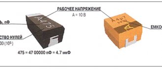
D. Mixed alphanumeric marking of capacity, tolerance, TKE, operating voltage
Unlike the first three parameters, which are marked in accordance with standards, the operating voltage of different companies has different alphanumeric markings.
| Code | Capacity |
| p10 | 0.1 pF |
| IP5 | 1.5 pF |
| 332p | 332 pF |
| 1NO or 1nO | 1.0 nF |
| 15H or 15n | 15 nF |
| 33H2 or 33n2 | 33.2 nF |
| 590H or 590n | 590 nF |
| m15 | 0.15uF |
| 1m5 | 1.5 µF |
| 33m2 | 33.2 µF |
| 330m | 330 µF |
| 1mO | 1 mF or 1000 μF |
| 10m | 10 mF |
Code marking of electrolytic capacitors for surface mounting
The following coding principles are used by such well-known companies as Hitachi and others. There are three main coding methods:
A. Marking with 2 or 3 characters
The code contains two or three characters (letters or numbers) indicating the operating voltage and rated capacity. Moreover, the letters indicate voltage and capacitance, and the number indicates the multiplier. In the case of a two-digit designation, the operating voltage code is not indicated.
| Code | Capacitance [µF] | Voltage [V] |
| A6 | 1,0 | 16/35 |
| A7 | 10 | 4 |
| AA7 | 10 | 10 |
| AE7 | 15 | 10 |
| AJ6 | 2,2 | 10 |
| AJ7 | 22 | 10 |
| AN6 | 3,3 | 10 |
| AN7 | 33 | 10 |
| AS6 | 4,7 | 10 |
| AW6 | 6,8 | 10 |
| CA7 | 10 | 16 |
| CE6 | 1,5 | 16 |
| CE7 | 15 | 16 |
| CJ6 | 2,2 | 16 |
| CN6 | 3,3 | 16 |
| CS6 | 4,7 | 16 |
| CW6 | 6,8 | 16 |
| DA6 | 1,0 | 20 |
| DA7 | 10 | 20 |
| DE6 | 1,5 | 20 |
| DJ6 | 2,2 | 20 |
| DN6 | 3,3 | 20 |
| DS6 | 4,7 | 20 |
| DW6 | 6,8 | 20 |
| E6 | 1,5 | 10/25 |
| EA6 | 1,0 | 25 |
| EE6 | 1,5 | 25 |
| EJ6 | 2,2 | 25 |
| EN6 | 3,3 | 25 |
| ES6 | 4,7 | 25 |
| EW5 | 0,68 | 25 |
| GA7 | 10 | 4 |
| GE7 | 15 | 4 |
| GJ7 | 22 | 4 |
| GN7 | 33 | 4 |
| GS6 | 4,7 | 4 |
| GS7 | 47 | 4 |
| GW6 | 6,8 | 4 |
| GW7 | 68 | 4 |
| J6 | 2,2 | 6,3/7/20 |
| JA7 | 10 | 6,3/7 |
| JE7 | 15 | 6,3/7 |
| JJ7 | 22 | 6,3/7 |
| JN6 | 3,3 | 6,3/7 |
| JN7 | 33 | 6,3/7 |
| JS6 | 4,7 | 6,3/7 |
| JS7 | 47 | 6,3/7 |
| JW6 | 6,8 | 6,3/7 |
| N5 | 0,33 | 35 |
| N6 | 3,3 | 4/16 |
| S5 | 0,47 | 25/35 |
| VA6 | 1,0 | 35 |
| VE6 | 1,5 | 35 |
| VJ6 | 2,2 | 35 |
| VN6 | 3,3 | 35 |
| VS5 | 0,47 | 35 |
| VW5 | 0,68 | 35 |
| W5 | 0,68 | 20/35 |
Alphanumeric designation
If you disassemble old Soviet equipment, then everything will be quite simple - on the cases it says “22pF”, which means 22 picofarads, or “1000 uF”, which means 1000 microfarads. Old Soviet capacitors were usually large enough to allow such “long texts” to be written on them.
Global, so to speak, alphanumeric marking involves the use of letters of the Latin alphabet:
- p – picofarads,
- n – nanofarads
- m – microfarads.
At the same time, it is useful to remember that if we conventionally take picofarad as a unit of capacity (although this is not entirely correct), then the letter “p” will denote units, the letter “n” – thousands, the letter “m” – millions. In this case, the letter will be used as a decimal point. Here is a clear example, a capacitor with a capacity of 2200 pF, according to this system will be designated 2n2, which literally means “2.2 nanofarads”. Or a capacitor with a capacity of 0.47 µF will be designated m47, that is, “0.47 microfarads”.
It will be interesting➡ What is a variable capacitor
Moreover, domestically produced capacitors have similar markings in Cyrillic, that is, picofarads are designated by the letter “P”, nanofarads by the letter “N”, microfarads by the letter “M”. But the principle is the same: 2H2 is 2.2 nanofarads, M47 is 0.47 microfarads. For some types of miniature capacitors, “μF” is designated by the letter R, which is also used as a decimal point, for example:
1R5 =1.5 µF.
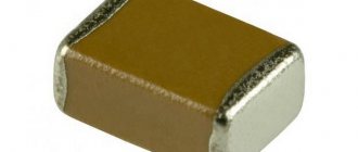
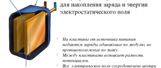
About the capacitor
The basic structure of a capacitor has a simple explanation. Between the two capacitor plates there is a dielectric that insulates the two conducting surfaces. Thus, a capacitor is a passive device capable of storing electrical charge.
The capacitor films, dielectric and design largely determine the properties of the capacitor, namely the ability to store a charge that is proportional to the voltage applied to its plates. This proportionality, called capacitance, is considered an essential feature of the capacitor.
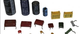
Technologically, capacitors can be divided into three types:
- electrostatic;
- electrolytic;
- other electrochemical devices (double-layer).
The use of a capacitor depends on the type and purpose of the circuit. A buffer capacitor element is used to intercept peak loads. These elements are used in filters to suppress interference and build resonant circuits.
How to make a non-polar capacitor from a polar one
Capacitor CBB61
Sometimes situations arise when you need to use a non-polar capacitor element for an amplifier or other device, but only polar ones are at hand. You can replace a non-polarized capacitor with a pair of products with poles with a capacitance twice that required in the circuit. They are connected to each other counter-series: identical (positive or negative) terminals are connected to each other, the other two are soldered into the circuit.
The structure of NEC with oxides on both plates has a similar principle. Due to this, such products have larger dimensions than polar products with the same electrolytic capacitance parameter. Based on the same mechanism, they produce NEC with a start option, designed for operation in alternating current circuits.
Connecting non-polar devices to produce a polar one
Constant capacitor
Divided into two main types:
Small-sized non-polarized capacitor elements can be connected in any direction. There are different types, but ceramic is the most widely used and suitable for most purposes.
On electrical circuits they are indicated by a pair of short parallel lines perpendicular to the connecting circuit lines. The capacitance value of the element is often placed nearby.
Designation of a capacitor with a constant capacitance
Important! Sometimes in foreign schemes the designation MFD is found. These are not megafarads, but μF.
Possible capacity units:
- micro (μ) means 10 to the -6 power of farad;
- nano (n) – 10 to the -9 degree farad;
- pico (p) – 10 to the -12 degree farad.
The capacitance value is also applied to the surface of the capacitor itself. It is often indicated without unit symbols, especially on small elements. For example, 0.1 is 1 µF = 100 nF.
Sometimes writing units is used instead of a decimal point. If the designation 4n7 appears, this means 4.7 nF.
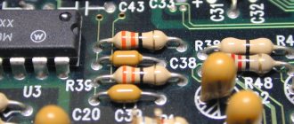
Capacitor number code
Digital code is often used on small items where printing is difficult:
- the first two numbers are the initial digits of the capacity value;
- the third shows the number of zeros, and the value itself is measured in pF;
- letters may indicate tolerances and voltage ratings.
Polarized capacitors
Capacitor elements of this type must be connected according to the poles. This is shown in the diagram by the “+” symbol. On the device itself it is indicated by markings that identify the “plus”. For cylindrical parts, a longer lead is usually a plus. Polarized capacitors are not damaged during soldering.
Electrolytic capacitors are the most widely used type of polarized capacitor element. They are available in two versions:
- cylindrical, with both terminals at one end;
- axial, with leads at each end.
Cylindrical ones tend to be a little smaller and cheaper.
The actual dimensions of such elements are large enough to clearly indicate on them the value of capacitance, rated voltage and indicate the “positive” terminal. Therefore they are easy to identify.
Important! When turned on in the opposite direction, the elements can be damaged and even explode, so polarity must be strictly adhered to.
The voltage rating of electrolytic capacitors is quite low. In the absence of clear requirements, it is better to choose a part with a rating slightly higher than the circuit voltage.
The electrolytic capacitor element in the diagrams can be indicated in three versions, shown in the figure.
Designation of polarized capacitors
Tantalum capacitors
Tantalum capacitors are polarized and have low breakdown voltage. They have very small dimensions and are used in special situations where size is important.
On the latest models of tantalum capacitor elements, the value of capacitance, voltage and “positive” terminal are indicated. Older models have a color code system that conventionally indicates capacity.
The code consists of two stripes at the top of the element (for two digits) and a color spot indicating the number of zeros. The correspondence of color values for specific containers is determined from the tables. A gray spot means that the capacitive value in uF should be multiplied by 0.01, white - by 0.1. The lower band near the capacitor terminals gives the voltage value:
- yellow – 6.3 V;
- black – 10 V;
- green – 16 V;
- blue – 20 V;
- gray – 25 V;
- white – 30 V;
- pink – 35 V.
Important! The “positive” contact is always on the right side of the element, if you place it with the color spot facing you.
Marking of imported capacitors
To date, the standards that have been adopted from the IEC apply not only to foreign types of equipment, but also to domestic ones. This system involves applying a code type marking to the product body, which consists of three direct numbers.
The two numbers that are located from the very beginning indicate the capacity of the item and in units such as picofarads. The number that is located third in order is the number of zeros. Let's look at this using the example of 555 - that's 5,500,000 picofarads. In the event that the capacity of the product is less than one picofarad, then the number zero is indicated from the very beginning.
There is also a three-digit type of encoding. This type of application is used exclusively for parts that are highly precise.
Color coding of imported capacitors
The designation of names on an object such as a capacitor has the same production principle as on resistors. The first stripes on two rows indicate the capacity of this device in the same measurement units. The third stripe has a designation indicating the number of immediate zeros. But at the same time, the blue color is completely absent; blue is used instead.
It is important to know that if the colors are the same in a row, then it is advisable to create gaps between them so that it is clearly understood. Indeed, in another case, these stripes will merge into one.
Variable capacitors
This type of capacitor element is mainly used in radio circuits. The element consists of two disk systems. One is fixed permanently, the other can rotate, entering the gaps between the stationary disks. Variable parts have small capacitances, 100-500 pF, and are not used in electrical synchronization circuits due to the small capacitive value and limited limits of available values. Instead, conventional capacitors with fixed capacitance values and variable resistors are used.
Designation of variable capacitors
In the diagram, variable capacitors are represented by a capacitor symbol crossed out by an inclined arrow, and instead of the exact capacitance value, the limits of its change are written.
Capacitor trimmers
A type of variable capacitor elements are trimmers, these are miniature parts with variable capacitance. They are mounted directly on the printed circuit board, and the capacitive value changes only during the setup period of the circuit. That's why they are also called tuning ones. Adjustment is made using a screwdriver.
Designation of trimmer capacitor
The capacitive value of the trimmer is usually less than 100 pF. On the electrical diagram, the trimmer is indicated as a variable capacitor with an arrow, only the arrow has a perpendicular line instead of a point. The range of capacitance change is written next to it.
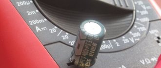
How to test a non-polar capacitor with a multimeter
To carry out the testing procedure, the device will need to be set to ohmmeter mode. Its main purpose is to measure the resistance parameter. When working with this group of elements, the leakage resistance is checked. Working probes are connected to the terminals of the capacitor being tested. Now you need to look at the readings of the device. If the screen displays one, the resistance value is greater than 2 megohms. This is considered normal. If the resistance is lower, there is significant leakage.
Important! Avoid holding the terminals of the device under test and the probes of the measuring device with both hands. This will lead to incorrect measurement results.
Checking with a multimeter
Ionistor
The ionistor is called a supercapacitor. It is a two-layer element with a relatively high capacity (0.22-10 F). The structure of a supercapacitor is different from that of a conventional electrolytic part. In the double layer, a zone of stationary charge carriers is formed at the interface between the electrode surface and the electrolyte, where energy is stored as an electrostatic field, in contrast to the chemical energy of the electrolytic capacitor element. Since the boundary layer is extremely thin and the electrode surface is large, high capacitance is achieved, making the supercapacitor suitable for use as a power supply.
Ionistor and its designation