The most common failure of modern electronics is the failure of electrolytic capacitors. If, after disassembling the case of an electronic device, you notice that there are capacitors on the printed circuit board with a deformed, swollen body, from which toxic electrolyte is oozing, then it’s time to figure out how to recognize a breakdown or defect in the capacitor and select an adequate replacement. Having professional soldering flux, solder, a soldering station, and a set of new capacitors, you can easily “revive” any electronic device with your own hands.
In essence, a capacitor is a radio-electronic component, the main purpose of which is the accumulation and release of electricity for the purpose of filtering, smoothing and generating alternating electrical oscillations. Any capacitor has two most important electrical parameters: capacitance and the maximum direct voltage that can be applied to the capacitor without breakdown or destruction. Capacitance, as a rule, determines how much electrical energy a capacitor can absorb if a constant voltage not exceeding a given limit is applied to its plates. Capacitance is measured in Farads. The most widely used capacitors are those whose capacitance is calculated in microfarads (μF), picofarads (pF) and nanofarads (nF). In many cases, it is recommended to replace a faulty capacitor with a serviceable one that has similar capacitance characteristics. However, in repair practice there is an opinion that in power supply circuits it is possible to install a capacitor with a capacity slightly higher than the factory parameters. For example, if we want to replace a ruptured electrolyte with 100 µF 12 Volt in the power supply, which is designed to smooth out fluctuations after the diode rectifier bridge, we can safely set the capacitance even to 470 µF 25 V. Firstly, an increased capacitor capacity will only reduce ripple, which in itself is not bad for a power supply. Secondly, an increased voltage limit will only increase the overall reliability of the circuit. The main thing is that the space allocated for installing the capacitor is suitable.
Why do electrolytic capacitors explode?
The most common reason why an electrolytic capacitor explodes is excess voltage between the capacitor plates. It is no secret that in many Chinese-made devices, the maximum voltage parameter exactly corresponds to the applied voltage. According to their idea, capacitor manufacturers did not foresee that when a capacitor is normally included in an electrical circuit, the maximum voltage will be supplied to its contacts. For example, if the capacitor says 16V 100uF, then you should not connect it to a circuit where 15 or 16V will be constantly supplied to it. Of course, he will withstand such abuse for some time, but the safety margin will be practically zero. It is much better to install such capacitors in a circuit with a voltage of 10–12V, so that there is some voltage reserve.
Current power through resistor
Let alternating current flow through a resistor with a resistance of . The voltage across the resistor, as we know, oscillates in phase with the current:
Therefore, for instantaneous power we obtain:
(2)
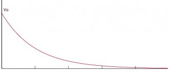
The graph of power (2) versus time is shown in Fig. 1. We see that the power is non-negative all the time - the resistor takes energy from the circuit, but does not return it back to the circuit.
Rice. 1. AC power through resistor
The maximum value of our power is related to the amplitudes of current and voltage by the usual formulas:
In practice, however, what is of interest is not the maximum, but the average
current power. This is understandable. Take, for example, an ordinary light bulb that is lit in your home. A current with a frequency of Hz flows through it, i.e., fluctuations in current and voltage occur per second. It is clear that over a sufficiently long time, a certain average power is released from the light bulb, the value of which is somewhere between and . Where exactly?
Look again carefully at Fig. 1. Don’t you have an intuitive feeling that the average power corresponds to the “middle” of our sinusoid and therefore takes on the value ?
This feeling is absolutely true! The way it is. Of course, we can give a mathematically strict definition of the average value of a function (in the form of some integral) and confirm our guess with direct calculation, but we don’t need this. An intuitive understanding of a simple and important fact is enough:
the average value of the square of the sine (or cosine) over the period is equal to
.
This fact is illustrated in Figure 2.
Rice. 2. The average value of the squared sine is
So, for the average value of the current power across the resistor we have:
(3)
In connection with these formulas, the so-called active
(or
effective
) values of voltage and current (in fact, these are nothing more than the
root mean square
values of voltage and current. We have already encountered this: the root mean square speed of the molecules of an ideal gas (sheet “Equation of State of an Ideal Gas”):
(4)
Formulas (3), written in terms of effective values, are completely similar to the corresponding formulas for direct current:
Therefore, if you take a light bulb, connect it first to a constant voltage source, and then to an alternating voltage source with the same effective value, then in both cases the light bulb will burn equally brightly.
The effective values (4) are extremely important for practice. It turns out that AC voltmeters and ammeters show exactly the effective values
(that's how they are designed).
Know also that the notorious volts from the outlet are the effective
value of the household power supply voltage.
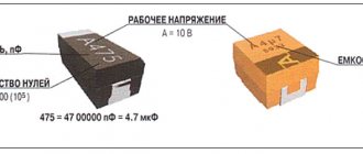
Polarity of connection of electrolytic capacitors
Electrolytic capacitors have negative and positive electrodes. As a rule, the negative electrode is identified by the markings on the body (a white longitudinal strip behind the “-” signs), and the positive plate is not marked in any way. The exception is domestic capacitors, where, on the contrary, the positive terminal is marked with a “+” sign. When replacing capacitors, it is necessary to compare and check whether the polarity of the capacitor connection corresponds to the markings on the printed circuit board (the circle where there is a shaded segment). By matching the negative strip with the shaded segment, you will correctly insert the capacitor. All that remains is to cut off the legs of the capacitor, process the soldering points and solder them properly. If you accidentally reverse the polarity of the connection, then even a completely new and completely serviceable capacitor will simply rupture, simultaneously smearing all adjacent components and the printed circuit board with conductive electrolyte.
A little about security
It is no secret that replacing low-voltage capacitors can only be harmful to health if the polarity connection is incorrect. The first time you turn it on, the capacitor will explode. The second danger that can be expected from capacitors is the voltage between its plates. If you've ever taken apart computer power supplies, you've probably noticed the huge 200V electrolytes. It is in these capacitors that dangerous high voltages remain that can seriously injure you. Before replacing the capacitors of the power supply, we recommend completely discharging it either with a resistor or a 220V neon lamp.
Helpful advice: such capacitors do not like to be discharged through a short circuit, so do not short-circuit their terminals with a screwdriver to discharge them.
Starting and running capacitors are used to start and operate electric motors operating in a single-phase 220 V network.
That's why they are also called phase shifters.
Installation location: between the power line and the starting winding of the electric motor.
Symbol for capacitors in diagrams
The graphic designation on the diagram is shown in the figure, the letter designation is C and the serial number according to the diagram.
How to choose a capacitor depending on its characteristics?
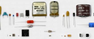
There are many types of capacitors. The shape of these elements can be very diverse:
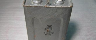
- roll low-frequency: they are a paper tape, lined with foil and rolled into a roll;
- lamellar: collected in sealed bags, covered with protective enamel;
- tubular: shaped like a ceramic tube and a silver conductive layer;
- disk: with a dielectric in the form of a ceramic disk (high-frequency capacitors usually have the form of a disk or tube);
- Cast sectional ones, intended for installation in microcircuits, have 2 grooves, between which silver paste is poured.
Let's look at how to choose a capacitor based on the type of dielectric. Based on the type of insulator, this device can be:
- electrolytic (aluminum or tantalum): the anode is a metal plate, the dielectric is an oxide film, and the cathode is an electrolyte;
- film and metal film: with insulators in the form of polypropylene, polyester or polystyrene film laid between layers of foil; despite the minimal capacity, they are capable of operating at elevated voltages in high-frequency circuits;
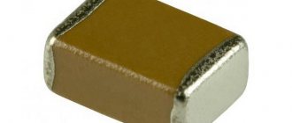
- small-capacity ceramic: the dielectric in it is ceramic plates; work well with signals of changing polarity;
- paper: used less often, larger in size; The insulator is oiled or non-oiled paper.
Basic parameters of capacitors
Capacitor capacity
- characterizes the energy that a capacitor is capable of accumulating, as well as the current that it is capable of passing through itself. Measured in Farads with a multiplying prefix (nano, micro, etc.).
The most commonly used values for run and start capacitors range from 1 μF to 100 μF.
Nominal voltage of the capacitor -
voltage at which the capacitor is able to operate reliably and for a long time, maintaining its parameters.
Well-known capacitor manufacturers indicate on its body the voltage and the corresponding guaranteed operating time in hours, for example:
- 400 V - 10,000 hours
- 450 V - 5000 hours
- 500 V - 1000 hours
Properties
From the description it is clear that for direct current the capacitor is an insurmountable barrier, except in cases of dielectric breakdown. In such electrical circuits, a radio element is used to accumulate and store electricity on its electrodes. A change in voltage occurs only in cases of changes in the current parameters in the circuit. These changes can be read and acted upon by other circuit elements.
In sinusoidal current circuits, a capacitor behaves like an inductor. It passes alternating current, but cuts off the direct component, which means it can serve as an excellent filter. Such radio-electronic elements are used in feedback circuits, included in oscillatory circuit circuits, etc.
Another property is that variable capacitance can be used to shift phases. There are special starting capacitors (Fig. 5) used to start three-phase electric motors in single-phase electrical networks.
Rice. 5. Start capacitor with wires
Checking the starting and running capacitors
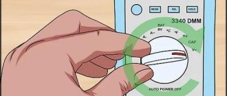
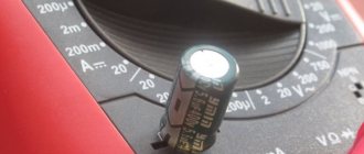
You can check the capacitor using a capacitor capacitance meter; such devices are produced both separately and as part of a multimeter, a universal device that can measure many parameters. Let's consider checking with a multimeter.
- de-energize the air conditioner
- discharge the capacitor by short-circuiting its terminals
- remove one of the terminals (any)
- We set the device to measure the capacitance of capacitors
- We lean the probes against the terminals of the capacitor
- read the capacity value from the screen
All devices have different designations for the capacitor measurement mode; the main types are shown below in the pictures.
In this multimeter, the mode is selected by a switch; it must be set to Fcx mode. The probes must be inserted into the sockets marked Cx.
Switching the capacitance measurement limit is manual. Maximum value 100 µF.
This measuring device has an automatic mode, you just need to select it, as shown in the picture.
The Mastech measuring tweezers also automatically measure capacitance, you just need to select the mode with the FUNC button, pressing it until the F indication appears.
To check the capacitance, we read its value on the capacitor body and set a deliberately larger measurement limit on the device. (If it's not automatic)
For example, the nominal value is 2.5 μF (μF), on the device we set 20 μF (μF).
After connecting the probes to the terminals of the capacitor, we wait for the readings on the screen, for example, the time to measure a capacitance of 40 μF with the first device is less than one second, with the second one more than one minute, so you should wait.
If the rating does not correspond to that indicated on the capacitor body, then it must be replaced and, if necessary, an analogue must be selected.
Signs of a bad capacitor
Before choosing a capacitor, you should unsolder the failed device and determine its parameters. Signs of malfunction of this element may include:
- “bloating”, deformation of the lid;
- decrease in capacitance and complex electrical resistance (impedance): an ohmometer is used to determine their value; its probes are applied to one of the pre-soldered terminals of the capacitor; if there is a break, the instrument needle will deviate towards “infinity”; a malfunction of the capacitor is also indicated by a decrease in its capacity;
Indirect signs of failure of one or more capacitors are instability of the computer, its periodic freezing, rebooting, increased power consumption of one of the nodes, or complete failure of the PC.
Important! It is extremely undesirable to delay replacing a capacitor involved in the power supply circuit of the most important elements, for example, a processor. This may lead to its failure.
Replacement and selection of starting/running capacitor
If you have an original capacitor, then it is clear that you simply need to put it in place of the old one and that’s it. Polarity does not matter, that is, the terminals of the capacitor do not have the designations plus “+” and minus “-” and they can be connected in any way.
It is strictly forbidden to use electrolytic capacitors (you can recognize them by their smaller sizes, with the same capacity, and the plus and minus markings on the case). As a consequence of use - thermal destruction. For these purposes, manufacturers specially produce non-polar capacitors for operation in an alternating current circuit, which have convenient mounting and flat terminals for quick installation.
If the required value is not available, it can be obtained by connecting capacitors in parallel
. The total capacitance will be equal to the sum of the two capacitors:
C total = C 1 + C 2 +…C p
That is, if we connect two 35 μF capacitors, we get a total capacity of 70 μF, the voltage at which they can operate will correspond to their rated voltage.
Such a replacement is absolutely equivalent to one capacitor of larger capacity.
Types of capacitors
To start powerful compressor engines, oil-filled non-polar capacitors are used.
The housing is filled with oil inside for good heat transfer to the surface of the housing. The body is usually metal or aluminum.
The most affordable capacitors of this type are CBB65
.
To start less powerful loads, such as fan motors, dry capacitors are used, the housing of which is usually plastic.
The most common capacitors of this type are CBB60
,
CBB61
.
The terminals are double or quadruple for ease of connection.
Having decided to replace a capacitor on a printed circuit board, the first step is to select a replacement capacitor. As a rule, we are talking about an electrolytic capacitor, which, due to the exhaustion of its working life, began to create an abnormal mode for your electronic device, or the capacitor burst due to overheating, or maybe you just decided to install a newer or better one.
Selecting a suitable replacement capacitor
The parameters of the replacement capacitor must certainly be suitable: its rated voltage should in no case be lower than that of the capacitor being replaced, and the capacitance should not be lower, or maybe 5-10 percent higher (if this is permissible according to the rules known to you). circuit diagram of this device) than it was originally.
Finally, make sure the new capacitor will fit into the space that its predecessor will leave. If it turns out to be a little smaller in diameter and height, it’s not a big deal, but if the diameter or height is larger, components located nearby on the same board may interfere or it will rest against the elements of the case. It is important to take these nuances into account. So, the replacement capacitor has been selected, it suits you, now you can start dismantling the old capacitor.
Getting ready for the process
Now it will be necessary to remove the faulty capacitor from the board and prepare a place for installing a new one here. To do this, you will need, of course, and it is also convenient for this action to prepare a piece of copper braid for removing solder. As a rule, a soldering iron power within 40 W will be quite sufficient even if refractory solder was initially used on the board.
As for copper braiding to eliminate solder, if you don’t have one, it’s very easy to make it yourself: take a piece of not very thick copper wire consisting of thin copper strands, remove the insulation from it, lightly (you can use simple pine rosin) - Now these flux-impregnated veins will easily, like a sponge, absorb solder from the legs of the soldered capacitor.
Soldering the old capacitor
First, look at the polarity of the soldered capacitor on the board: which way is it facing minus, so that when you solder a new one, you will not make a mistake with the polarity. Usually the negative leg is marked with a stripe. So, when the braid for desoldering is prepared, and the soldering iron is already warm enough, first lean the braid against the base of the capacitor legs that you decided to free from solder first.
Carefully melt the solder on the leg directly through the braid so that the braid also heats up and quickly draws the solder from the board. If there is too much solder on the leg, move the braid as it fills with solder, collecting all the solder from the leg onto it so that the leg ends up free of solder. Do the same with the second leg of the capacitor. Now the capacitor can be easily pulled out by hand or tweezers.
Soldering in a new capacitor
The new capacitor must be installed in compliance with the polarity, that is, the negative leg is in the same place where the negative leg of the soldered one was. Usually the minus leg is indicated by a stripe, and the plus leg is longer than the minus leg. Treat the capacitor legs with flux.
Insert the capacitor into the holes. There is no need to shorten the legs in advance. Bend the legs slightly in different directions so that the capacitor stays in place well and does not fall out.
Now, warming up the leg near the board itself with the tip of the soldering iron tip, poke the solder towards the leg so that the leg is enveloped, moistened, and surrounded by solder. Do the same with the second leg. When the solder has cooled, all you have to do is shorten the legs of the capacitor with wire cutters (to the same length as the adjacent parts on your board).
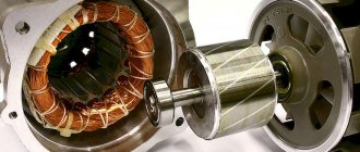
In the element base of a computer (and not only) there is one bottleneck - electrolytic capacitors. They contain an electrolyte; the electrolyte is a liquid. Therefore, heating such a capacitor leads to its failure, as the electrolyte evaporates. And heating in the system unit is a regular occurrence.
Therefore, replacing capacitors is a matter of time. More than half of the failures of motherboards in the middle and lower price categories are due to dry or swollen capacitors. Even more often, computer power supplies break down for this reason.
Since the printing on modern boards is very dense, replacing capacitors must be done very carefully. You can damage and not notice a small unframed element or break (short) tracks, the thickness and distance between which is slightly greater than the thickness of a human hair. It’s quite difficult to fix something like this later. So be careful.
So, to replace capacitors you will need a soldering iron with a thin tip with a power of 25-30 W, a piece of thick guitar string or a thick needle, soldering flux or rosin.
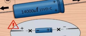
If you reverse the polarity when replacing an electrolytic capacitor or install a capacitor with a low voltage rating, it may well explode. And here's what it looks like:
So, carefully select the replacement part and install it correctly. Electrolytic capacitors are always marked with a negative terminal (usually a vertical stripe of a different color from the body color). On the printed circuit board, the hole for the negative contact is also marked (usually with black shading or solid white). The ratings are written on the capacitor body. There are several of them: voltage, capacity, tolerances and temperature.
The first two are always present, the others may be absent. Voltage: 16V
(16 volts).
Capacitance: 220µF
(220 microfarads). These values are very important when replacing. The voltage can be chosen equal or with a higher nominal value. But the capacitance affects the charging/discharging time of the capacitor and in some cases can be important for a section of the circuit.
Therefore, the capacity should be selected equal to that indicated on the case. On the left in the photo below is a green swollen (or leaking) capacitor. In general, there are constant problems with these green capacitors. The most common candidates for replacement. On the right is a working capacitor, which we will solder.
The capacitor is soldered as follows: first find the legs of the capacitor on the back side of the board (for me this is the most difficult moment). Then heat one of the legs and lightly press the capacitor body from the side of the heated leg. When the solder melts, the capacitor tilts. Carry out a similar procedure with the second leg. Usually the capacitor is removed in two steps.
There is no need to rush, and there is no need to press too hard. The motherboard is not a double-sided PCB, but a multilayer one (imagine a wafer). Overdoing it can damage the contacts on the inner layers of the printed circuit board. So no fanaticism. By the way, long-term heating can also damage the board, for example, lead to peeling or tearing of the contact pad. Therefore, there is no need to press hard with a soldering iron either. We lean the soldering iron and press lightly on the capacitor.
After removing the damaged capacitor, it is necessary to make holes so that the new capacitor can be inserted freely or with little effort. For these purposes, I use a guitar string of the same thickness as the legs of the part being soldered. A sewing needle is also suitable for these purposes, but needles are now made of ordinary iron, and strings are made of steel. There is a chance that the needle will get caught in the solder and break when you try to pull it out. And the string is quite flexible and steel and solder adhere much worse than iron.
When removing capacitors, solder most often clogs the holes in the board. If you try to solder the capacitor in the same way that I advised you to solder it, you can damage the contact pad and the track leading to it. Not the end of the world, but a very undesirable occurrence. Therefore, if the holes are not clogged with solder, they simply need to be expanded. And if you do, then you need to press the end of the string or needle tightly to the hole, and on the other side of the board, lean the soldering iron against this hole. If this option is inconvenient, then the soldering iron tip should be leaned against the string almost at the base. When the solder melts, the string will fit into the hole. At this moment you need to rotate it so that it does not grab the solder.
After obtaining and expanding the hole, it is necessary to remove excess solder from its edges, if any, otherwise, during soldering of the capacitor, a tin cap may form, which can solder adjacent tracks in those places where the seal is dense. Pay attention to the photo below - how close the tracks are to the holes. Soldering this is very easy, but difficult to notice, since the installed capacitor interferes with the view. Therefore, it is very advisable to remove excess solder.
If you don’t have a radio market nearby, then most likely you can only find a used capacitor for replacement. Before installation, its legs should be treated, if necessary. It is advisable to remove all solder from the legs. I usually coat the legs with flux and tin them with a clean soldering iron tip, the solder collects on the soldering iron tip. Then I scrape the legs of the capacitor with a utility knife (just in case).
That's all, actually. We insert the capacitor, lubricate the legs with flux and solder. By the way, if you use pine rosin, it is better to crush it into powder and apply it to the installation site than to dip a soldering iron in a piece of rosin. Then it will work out neatly.