The main elements of overhead lines are wires, insulators, linear fittings, supports and foundations. On overhead lines of three-phase alternating current, at least three wires are suspended, constituting one circuit; on direct current overhead lines - at least two wires.
Based on the number of circuits, overhead lines are divided into single, double and multi-circuit. The number of circuits is determined by the power supply circuit and the need for its redundancy. If the power supply scheme requires two circuits, then these circuits can be suspended on two separate single-circuit overhead lines with single-circuit supports or on one double-circuit overhead line with double-circuit supports. The distance / between adjacent supports is called the span, and the distance between anchor-type supports is called the anchor section.
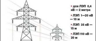
Wires suspended on insulators (A - the length of the garland) to the supports (Fig. 5.1, a) sag along the catenary line. The distance from the suspension point to the lowest point of the wire is called the sag /. It determines the size of the wire approaching the ground A, which for populated areas is equal to: to the surface of the earth up to 35 and PO kV - 7 m; 220 kV - 8 m; to buildings or structures up to 35 kV - 3 m; 110 kV - 4 m; 220 kV - 5 m. Span length / is determined by economic conditions. The span length up to 1 kV is usually 30...75 m; PO kV - 150...200 m; 220 kV - up to 400 m.
Types of power transmission towers
Depending on the method of hanging the wires, the supports are:
- intermediate, on which the wires are secured in supporting clamps;
- anchor type, used for tensioning wires; on these supports the wires are secured in tension clamps;
- corner ones, which are installed at the angles of rotation of overhead lines with wires suspended in supporting clamps; they can be intermediate, branch and corner, end, anchor corner.
On a larger scale, overhead line supports above 1 kV are divided into two types: anchor ones, which fully support the tension of wires and cables in adjacent spans; intermediate, not perceiving the tension of the wires or perceiving partially.
On overhead lines, wooden supports are used (Fig. 5L, b, c), new generation wooden supports (Fig. 5.1, d), steel (Fig. 5.1, e) and reinforced concrete supports.
Single-circuit and double-circuit overhead lines
In distribution networks 0.4 kV, 10 kV, single-circuit and double-circuit overhead power lines are used. A single circuit overhead line is used to transmit three-phase standard voltage. Double circuit overhead line is used to transmit two circuits having different directions. Let’s say from the Substation two subscribers over several kilometers have the same direction, here they use a double-circuit line, and then they diverge into two single-circuit overhead lines. According to the design between these types of overhead lines, the linear fittings and, in more detail, the traverses change.
Overhead Line (OHL) Design
An overhead power line is an electrical installation, and all installations have their own designs and contain:
1. Supports.
2. Traverses.
3. Insulators.
4.Wire.
5.Protection from thunderstorms and overvoltages
6.Grounding.
Wooden overhead line supports
Wooden overhead line poles are still common in countries with forest reserves. The advantages of wood as a material for supports are: low specific gravity, high mechanical strength, good electrical insulating properties, natural round assortment. The disadvantage of wood is its rotting, to reduce which antiseptics are used.
An effective method of combating rot is impregnation of wood with oily antiseptics. In the USA there is a transition to laminated wood supports.
For overhead lines with voltages of 20 and 35 kV, on which pin insulators are used, it is advisable to use single-column candle-shaped supports with a triangular arrangement of wires. On 6-35 kV overhead power lines with pin insulators, for any arrangement of wires, the distance between them D, m, must be no less than the values determined by the formula
where U is line voltage, kV; — the largest sag corresponding to the overall span, m; b—thickness of the ice wall, mm (no more than 20 mm).
For overhead lines 35 kV and above with suspended insulators with horizontal wires, the minimum distance between wires, m, is determined by the formula
The support post is made of a composite: the upper part (the post itself) is made of logs 6.5...8.5 m long, and the lower part (the so-called stepson) is made of reinforced concrete with a section of 20 x 20 cm, lengths 4.25 and 6.25 m or from logs 4.5...6.5 m long. Composite supports with reinforced concrete stepson combine the advantages of reinforced concrete and wooden supports: lightning resistance and resistance to rotting at the point of contact with the ground. The connection of the rack to the stepson is made with wire bands made of steel wire with a diameter of 4...6 mm, tensioned by twisting or a tension bolt.
Anchor and intermediate corner supports for 6-10 kV overhead lines are made in the form of an A-shaped structure with composite posts.
Schemes for the execution of EHV power transmission lines
Extra-high voltage (EHV) power lines can be single-circuit, double-circuit or multi-circuit. The number of circuits is determined primarily by the role of a given transmission line in the power system, as well as its rated voltage and the maximum power that needs to be transmitted. Since the capital costs of constructing an EHV power transmission line are quite significant, based on cost savings at the first stage of construction, it is advisable to construct single-circuit ultra-high voltage lines. However, this reduces the reliability of power transmission, since disconnecting a single-circuit line can lead to a power shortage in the receiving power system. Therefore, when choosing the number of circuits in a line, the following circumstances should be kept in mind. In cases where the line capacity does not exceed 10% of the total available power of the receiving power system and disconnecting the line will not lead to the need to disconnect part of the system load, since this system has sufficient power reserve, we can talk about the construction of a single-circuit line. It should also be taken into account that automatic reclosing devices (AR) significantly increase the reliability of single-circuit lines. In the event of a power shortage in the receiving system when a single-circuit line is disconnected, which cannot be replenished by the available reserve, it is necessary to take into account the resulting damage, which consists of two components. One of them occurs when a reserve is introduced due to the loading of uneconomical units in a given power system, which will require additional fuel. The other is related to the purchase of missing energy from neighboring power systems, which will lead to additional power flows through the interconnections by which a given system is connected to others. This damage must be taken into account in the feasibility study for the construction of a single-circuit line when compared with other options. Double-circuit EHV power transmission lines are more reliable and at the same time more expensive. Therefore, when designing power transmission, the need to construct a double-circuit line must be justified by technical and economic calculations. When connecting two systems of comparable power. It is advisable to use double-circuit lines. These two circuits may have common buses at the ends of the power line or terminate at two different substations of the systems being connected. Subsequently, intermediate substations can be built on this power transmission to power intermediate consumers or to communicate with power systems located along the line route.
Two fundamentally different schemes for the construction of double-circuit power transmission lines are possible - block and connected (Fig. 1). In a block diagram, one part of the station generators works on one of the line circuits, the other on the second circuit. Both circuits can go either to the same or to different node substations of the receiving system. The routes of these circuits may coincide or be different. Thus, the power transmission line is divided into two parts, loosely connected to each other. Such schemes have some advantage in that they save money due to less switching equipment at the transmitting end, in particular, due to the use of a generator-transformer-line circuit.
Rice. 1. Block and connected power line diagrams
However, such a block diagram also has a number of serious disadvantages, as a result of which it has not been used in the practice of designing and constructing ultra-high voltage power transmission lines. One of the disadvantages of this scheme is that when one circuit goes out of operation, a significant part of the power of the starting power plant is lost, another is that with a block scheme it is much more difficult to ensure high throughput of one circuit due to the lack of cross connections and transmission sectioning at intermediate points . The block diagram can only be used to connect a remote power station to a receiving system.
Such schemes were proposed at the very first stage of development of long-distance EHV power transmission. Currently, they are not considered even in the initial design stages. The use of block schemes at subsequent stages of development of the EHV network is also unacceptable. The development of electric power systems does not require the construction of separate, isolated elements, but the creation of a UHV power transmission network, in which large thermal, nuclear and hydraulic stations, as well as large substations that supply energy to industrial areas, would be the nodes of this network. Such opportunities are provided by connected circuits, where there are cross-connections between circuits along the entire length of the power transmission. As experience in the design and operation of such power transmission lines in the first stages of their existence has shown, switching points constructed every 250-300 km ensure that in case of accidents, only individual sections of each circuit are disconnected, which allows only a slight reduction in transmission capacity while maintaining the stability of the parallel operation of transmission generators. stations with a receiving system. In addition, they significantly facilitate the operation and repair of such power transmission lines. Subsequently, these switching points can be converted into intermediate substations designed to power the load that appears in their area, and ultimately turn into nodes of the EHV network. Therefore, all long EHV power transmission lines are currently being designed as elements of a developed EHV network. In Fig. Figure 2 shows simplified diagrams of the stage-by-stage development of the EHV network of one of the energy associations. At stage I, a new line connects several nodes of a developed network of a lower voltage level. At stage II, radial lines are connected to the substations of the new line to connect large power plants or powerful load nodes with a large annual increase in power. At stage III, the new voltage level becomes complexly closed, includes several circuits and turns, essentially, into a system-forming one. At the same time, the previously existing network of a lower voltage class is gradually turning into a distribution network, although its individual links, which have high throughput, retain their system-forming functions. High-value EHV power transmissions - three or more circuits - are, as a rule, not considered during design. If there is a need for multi-chain transmission to ensure a given throughput of a given connection, then this indicates that the rated transmission voltage is selected incorrectly and it is necessary to switch to a new, higher voltage level. Rice. 2. Phased development of the SVN network
However, the decision to construct a multi-circuit power transmission may be forced when the required higher voltage class has not yet been mastered, and the capacity of the power transmission line must be quite high. Such decisions were made, for example, in Canada and Brazil during the construction of the power transmission line of the already mentioned hydroelectric power stations on the river. Churchill and the Itaynu hydroelectric station, when it was necessary to transmit power of about 6 GW over a distance of over 800 km. The highest voltage levels in these countries were 735 and 765 kV, respectively. Therefore, three-circuit power lines were built, since under those conditions there could be no other solutions. Multi-circuit EHV power transmission lines can also be interconnected. Moreover, the increase in the number of circuits occurs as the connected systems develop and intersystem power flows increase, when moving to a higher level is impossible for the reason stated above or is simply impractical for both economic and engineering reasons. For example, in the UES of Russia there are multi-chain connections between the IPS of the Center and the IPS of the Middle Volga, the IPS of the Center and the IPS of the South (Ukraine), the IPS of Siberia and the IPS of Northern Kazakhstan. As a rule, these lines connect various nodes of the connected systems and in some cases have different rated voltages, for example 330 and 750 kV.
Naturally, the presence of these connections is taken into account in the calculations of intersystem power flows and modes of the UES of Russia. In these cases, it is customary to talk about the capacity not of a single line, but about the capacity of a section that includes all the lines connecting the systems under consideration.
Steel transmission towers
Steel supports are widely used on overhead lines with voltages of 35 kV and higher.
According to their design, steel supports can be of two types:
- tower or single-column (see Fig. 5.1, d);
- portal, which, according to the method of fastening, are divided into free-standing supports and supports with guy wires.
The advantage of steel supports is their high strength, the disadvantage is their susceptibility to corrosion, which requires periodic painting or the application of an anti-corrosion coating during operation.
The supports are made of rolled steel (usually an isosceles angle is used); high transition supports can be made of steel pipes. Steel sheets of various thicknesses are used in the connection nodes of the elements. Regardless of the design, steel supports are made in the form of spatial lattice structures.
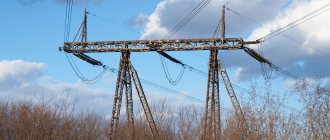
Power line design
Metal power line support.
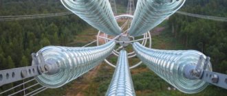
includes wires, insulators, supports (Fig.). The wires of overhead power lines must have good electrical properties. conductivity, mechanical strength, resistance to atmospheric and chemical conditions. influences. Basic electrical conductor Power transmission lines in Russia are powered by aluminum wires; Aluminum alloys with increased mechanical strength are widely used abroad. strength (Aldrey, Almelek, Akron), as well as high-temperature alloys with zirconium (working temperature up to 150–210 °C). Wires (non-insulated) are made by twisting from several layers (layers) of round or shaped wires; premiums apply. strengthened (so-called steel-aluminium) with cores twisted from wire rope steel. On power lines with rated voltages up to 220 kV, only single wires are used in each of the three phases. In power lines with a voltage of 330 kV and higher, to eliminate the appearance of an extended corona discharge on the wires (causing additional losses of electrical energy), split phases are used (instead of one phase wire of a large cross-section, several wires of a smaller cross-section are suspended together). Minimum the number of wires in the split phase increases according to the increase in the rated voltage of the power line: 330 kV – 2; 500 kV – 3; 750 kV – 4; 1150 kV – 8. Increasing the number of wires in a phase above the minimum allows you to proportionally increase the transmission capacity of the transmission line (i.e., the highest possible active power). Abroad and in Russia, self-supporting insulators are widely used on newly constructed power lines up to 35–110 kV. wires, which makes it possible to reduce phase-to-phase distances on supports and reduce the width of cleared clearings in forests.
Electric insulation is provided either by garlands of suspended disc insulators made of tempered glass, connected mechanically into chains, or by rod polymer insulators, the basis of which is a fiberglass rod, hermetically protected by a ribbed shell made of organosilicon. rubber. The advantages of polymer insulation are: low weight; ease of storage, transportation and installation; increased resistance to damage, etc. Fastening of wires to insulation and insulation to supports is carried out using components and products of air fittings. lines (wire clamps, earrings, staples, etc.).
To maintain the wires at a safe distance from the earth's (water) surface, insulating hangers and supports (wooden, reinforced concrete and metal), as well as other supporting structures and natural materials, are used. formations (rocks, brackets and racks on other engineering structures). Tree poles (for power lines up to 220 kV inclusive) in Russia are made of logs (pine, larch), the standard lengths of which are limited to a maximum size of 16 m. Abroad (USA, Canada), pole designs consisting of long laminated wood have been developed. elements, which makes it possible to use wood. supports at rated voltages up to 500 kV inclusive. Reinforced concrete in structures. supports (up to 500 kV inclusive) the racks are long (up to 26 m) conical. and cylindrical pipes with internal prestressed reinforcement and centrifuged concrete compaction. The transverse elements of such supports (traverses) are made from hot-rolled steel angles. For the production of metallic supports (for all voltages) carbon and low-alloy steels, structural aluminum alloys are used. aircraft type (Al – Mg – Si systems). Aluminum supports are most widespread in the USA and Canada. Structural diagrams of metal. supports are very diverse: single-post and portal, both free-standing and held in a normal spatial position with the help of guy wires attached to anchor plates immersed in the ground. Racks and traverses metal. the supports can have a design in the form of a 4- or 3-sided obelisk, the sides of which are connected flat lattice trusses. In Russia, conicals are becoming increasingly used. multifaceted steel supports made by bending a sheet blank using a special method. powerful computer-controlled press. Everything is metal. supports are installed on foundations, unlike trees. and reinforced concrete. supports Reinforced concrete is widely used. mushroom-shaped supports of several modifications, having a base plate and a stand with extended anchor bolts to secure the “shoe” of the support. The disadvantages of such foundations are their heavy weight and the need to dig a deep pit for installation, backfill it and then compact the soil. Pile foundations, for which reinforced concrete can be used, do not have these disadvantages. prismatic piles buried in the ground by vibration pressing, and steel screw piles. The foundations of steel polyhedral supports abroad (USA) are made by concreting in a pit at the installation site of the support using formwork and reinforcement. Reinforced concrete is used in Russia. large diameter tubular foundations and mushroom-shaped substrates installed in a circle.
Reinforced concrete power transmission towers
Reinforced concrete supports, compared to metal ones, are more durable and economical to operate, since they require less maintenance and repair (if you take the life cycle, then reinforced concrete ones are more energy-consuming). The main advantage of reinforced concrete supports is a reduction in steel consumption by 40...75%, the disadvantage is their large mass. According to the manufacturing method, reinforced concrete supports are divided into those concreted at the installation site (for the most part, such supports are used abroad) and factory-made.
The traverses are fastened to the trunk of the reinforced concrete support post using bolts passed through special holes in the rack, or using steel clamps that cover the trunk and have pins for attaching the ends of the traverse belts to them. Metal traverses are pre-hot-galvanized, so they do not require special care and supervision during operation for a long time.
Overhead line wires are made uninsulated, consisting of one or more twisted wires. Wires made from one wire, called single-wire (they are made with a cross-section from 1 to 10 mm2), have less strength and are used only on overhead lines with voltages up to 1 kV. Stranded wires, twisted from several wires, are used on overhead lines of all voltages.
The materials of wires and cables must have high electrical conductivity, have sufficient strength, and withstand atmospheric influences (in this regard, copper and bronze wires have the greatest resistance; aluminum wires are susceptible to corrosion, especially on sea coasts, where the air contains salts; steel wires are destroyed even under normal atmospheric conditions).
For overhead lines, single-wire steel wires with a diameter of 3.5 are used; 4 and 5 mm and copper wires with a diameter of up to 10 mm. The lower limit is limited due to the fact that wires of smaller diameter have insufficient mechanical strength. The upper limit is limited due to the fact that bends in larger diameter solid wire can cause permanent deformations in its outer layers that will reduce its mechanical strength.
Stranded wires, twisted from several wires, have great flexibility; such wires can be made of any cross-section (they are made with a cross-section from 1.0 to 500 mm2).
The diameters of individual wires and their number are selected so that the sum of the cross sections of the individual wires gives the required total cross-section of the wire.
As a rule, stranded wires are made from round wires, with one or more wires of the same diameter placed in the center. The length of the twisted wire is slightly greater than the length of the wire measured along its axis. This causes an increase in the actual mass of the wire by 1 ... 2% compared to the theoretical mass, which is obtained by multiplying the cross-section of the wire by its length and density. In all calculations, the actual weight of the wire specified in the relevant standards is taken.
Brands of bare wires indicate:
- letters M, A, AS, PS - wire material;
- in numbers - cross section in square millimeters.
Aluminum wire A can be:
- AT grade (solid unannealed)
- AM (annealed soft) alloys AN, AZh;
- AS, ASHS - made of steel core and aluminum wires;
- PS - made of steel wires;
- PST - made of galvanized steel wire.
For example, A50 denotes an aluminum wire with a cross-section of 50 mm2;
- AC50/8 - steel-aluminum wire with a cross-section of the aluminum part of 50 mm2, steel core of 8 mm2 (electrical calculations take into account the conductivity of only the aluminum part of the wire);
- PSTZ,5, PST4, PST5 - single-wire steel wires, where the numbers correspond to the diameter of the wire in millimeters.
Steel cables used on overhead lines as lightning protection cables are made of galvanized wire; their cross-section must be at least 25 mm2. On overhead lines with a voltage of 35 kV, cables with a cross section of 35 mm2 are used; on PO lines kV - 50 mm2; on lines 220 kV and above -70 mm2.
The cross-section of stranded wires of various brands is determined for overhead lines with voltages up to 35 kV according to the conditions of mechanical strength, and for overhead lines with voltages up to kV and higher - according to the conditions of corona losses. On overhead lines when crossing various engineering structures (communication lines, railways and highways, etc.), it is necessary to ensure higher reliability, therefore the minimum cross-sections of wires in crossing spans must be increased (Table 5.2).
When an air flow directed across the axis of the overhead line or at a certain angle to this axis flows around the wires, turbulence occurs on the leeward side of the wire. When the frequency of formation and movement of vortices coincides with one of the natural oscillation frequencies, the wire begins to oscillate in the vertical plane.
Such vibrations of a wire with an amplitude of 2...35 mm, a wavelength of 1...20 m and a frequency of 5...60 Hz are called vibration.
Typically, vibration of wires is observed at wind speeds of 0.6 ... 12.0 m/s;
Steel wires are not allowed to fly over pipelines and railways.
Vibration typically occurs in spans longer than 120 m and in open areas. The danger of vibration lies in the breakage of individual wires in the areas where they exit the clamps due to increased mechanical stress. Variable stresses arise from periodic bending of the wires as a result of vibration and the main tensile stresses are stored in the suspended wire.
For spans up to 120 m long, vibration protection is not required; Areas of any overhead lines protected from cross winds are also not subject to protection; at large crossings of rivers and water spaces, protection is required regardless of the voltage in the wires. On overhead lines with a voltage of 35...220 kV and above, vibration protection is performed by installing vibration dampers suspended on a steel cable, absorbing the energy of vibrating wires and reducing the vibration amplitude near the clamps.
When there is ice, the so-called dancing of wires is observed, which, like vibration, is excited by the wind, but differs from vibration in a larger amplitude, reaching 12... 14 m, and a longer wavelength (with one and two half-waves in the span). In a plane perpendicular to the axis of the overhead line, the wire. At a voltage of 35 - 220 kV, the wires are isolated from the supports with garlands of pendant insulators. To insulate 6-35 kV overhead lines, pin insulators are used.
Electric current passing through the overhead line wires releases heat and heats the wire. Under the influence of heating the wire, the following occurs:
- lengthening the wire, increasing the sag, changing the distance to the ground;
- change in wire tension and its ability to bear mechanical load;
- change in wire resistance, i.e. change in electrical power and energy losses.
All conditions can change if environmental parameters are constant or change together, affecting the operation of the overhead line wire. When operating overhead lines, it is considered that at the rated load current the wire temperature is 60...70″C. The temperature of the wire will be determined by the simultaneous effects of heat generation and cooling or heat sink. The heat dissipation of overhead line wires increases with increasing wind speed and decreasing ambient temperature.
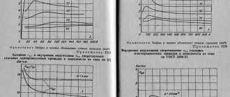
When the air temperature decreases from +40 to 40 °C and the wind speed increases from 1 to 20 m/s, heat losses change from 50 to 1000 W/m. At positive ambient temperatures (0...40 °C) and low wind speeds (1...5 m/s), heat losses are 75...200 W/m.
To determine the effect of overload on increasing voltage losses, first determine
where RQ is the resistance of the wire at a temperature of 02, Ohm; R0] - wire resistance at a temperature corresponding to the design load under operating conditions, Ohm; А/.у.с - coefficient of temperature increase in resistance, Ohm/°C.
An increase in wire resistance compared to the resistance corresponding to the design load is possible with an overload of 30% by 12%, and with an overload of 50% by 16%.
An increase in voltage loss AU at an overload of up to 30% can be expected:
- when calculating overhead lines at AU = 5% A?/30 = 5.6%;
- when calculating overhead lines on A17 = 10% D?/30 = 11.2%.
When the overhead line is overloaded to 50%, the increase in voltage loss will be equal to 5.8 and 11.6%, respectively. Taking into account the load diagram, it can be noted that when the overhead line is overloaded to 50%, voltage losses briefly exceed the permissible standard values by 0.8... 1.6%, which does not significantly affect the quality of electricity.
Classification of power lines
is based on a number of characteristics, the first of which is the type of current. They are distinguished: direct current lines (used to a limited extent, since direct current power transmission is mainly associated with the technical difficulties of creating effective inexpensive devices for converting alternating current into direct current at the beginning of the line, and direct current into alternating current at the end of the line) , three-phase alternating current (in terms of the length of overhead lines they are most widespread in the world), multiphase alternating current power lines (six- and twelve-phase) are not widely used. One of the main characteristics of a power transmission line is its throughput, i.e. the greatest power that can be transmitted along a power line, taking into account limiting factors. The power transmitted along three-phase alternating current power lines is related to its length, voltage and current load. According to the rated voltage, power lines are divided into low-voltage (up to 1 kV) and high-voltage (over 1 kV), among which there are medium (3–35 kV), high (110–220 kV), ultra-high (330–750 kV) and ultra-high ( over 1000 kV) voltages. The development of higher voltage levels is due to the need to transmit increasing flows of electricity over increasing distances and the desire to reduce losses from heating of overhead line wires, which are proportional to the square of the current (for example, the current will increase by 2 times, losses will increase by 4 times). According to the number of parallel circuits laid along a common route, overhead lines can be single-circuit (alternating current overhead lines having one set, i.e., three phase wires), double-circuit (overhead lines with two sets of phase wires) and multi-circuit (overhead lines having more than two sets of phase wires). wires). According to their topological characteristics, they distinguish between radial (power comes from a single source), main (several branches extend out) and branches (lines connected at one end to another power line at its intermediate point). According to the functional purpose of power lines, there are distribution lines (lines of local electrical networks), supply lines (lines of regional networks that provide power supply to power centers of distribution networks), as well as system-forming and intersystem, which directly connect different power systems and are intended for mutual exchange of power as in normal and emergency mode.