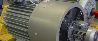
Brushless two-winding electric machines, in which one winding is powered from an alternating current electrical network with a constant frequency value, and the other is connected to a direct current excitation source, with the same rotation speeds of the machine rotor and its magnetic field. The main area of application is the conversion of mechanical energy into electricity.
Types of synchronous machines
There are several types of such machines, these are:
- Hydrogenerator - its rotor is distinguished by the presence of salient poles and is used in the production of electrical energy, operating at low speeds.
- Turbogenerator - characterized by a non-salient-pole generator design, operates using turbines of various types, the speed is characterized by a large number of shaft revolutions per minute, can reach up to 6000 rpm.
- Compensator - it generates reactive power, does not carry a load, is used to improve the quality of electrical energy due to improved power factor, and serves to stabilize voltage.
- An asynchronized dual-power machine - it connects the rotor and stator windings from a current source with different frequencies, creating a non-synchronous operating mode. It features a stable operating mode, serves as a phase current converter, and is used to solve highly specialized problems.
- Bipolar impact generator - the work consists of using a short circuit mode, it operates briefly for a fraction of a second, it performs the task of testing high voltage equipment.
- Synchronous motors are divided into a number of models designed to perform various purposes, these are: stepper models, gearless, inductor, hysteresis, and contactless motors.
General operating principle
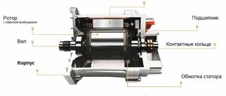
According to its basic design, the stator is considered the armature of the machine and has a multiphase winding, most often designed for three phases. It acts as an inductor, the rotor (excitation) winding serves to create a flux of excitation magnetic induction, it is powered using slip rings, through a brush mechanism, from a source (exciter armature). The design of the machine, first of all, depends on the required rotation speed, this mainly affects the design features of the rotor; there are two main types, these are salient-pole and non-salient-pole types.
Design features of a salient pole rotor
Salient pole rotor
In the first case, the rotor has two or more salient poles. The rods (coils) are secured in the grooves using wedges made of non-magnetic insulating material.
The rods perform the function of excitation windings. The core is made of electrical steel. The pole pieces contain the winding rods intended for starting; they are made of brass, which is characterized by high resistivity.
A similar winding, a “squirrel cage”, which has copper coils in its design, is used to construct generators; it plays a damping role and acts as a damper, because it helps reduce rotor instability that appears during the transient regime.
The cessation of oscillations occurs after the appearance of eddy currents that appear during short circuits in the rotor with poles of significant weight.
The non-salient pole rotor is used for the design of high-power synchronous units. They are distinguished by high speed characteristics. The shaft speed can reach a limit of about 3000 rpm.
This parameter makes it impossible to use a salient pole rotor in high-speed machines due to the difficulty of attaching poles and field windings with a small number of pole pairs.
The rotor magnetic core is manufactured as a single unit with the machine shaft and is made from a single forging. Its set is made of durable alloy steel; in the grooves, a winding is formed from copper conductors with a silver additive, this is done for increased thermal resistance.
Why do you need to know the rotational speed of the electric motor shaft?
In the process of selecting a drive, you should ensure not only that the selected model corresponds to the specifics of use and operating conditions, but also that the rotation speed of the asynchronous motor corresponds to the power required for normal operation of the mechanism.
Thus, for lifting mechanisms (beam cranes, hoists, winches, various types of cranes), a high engine rotor speed is not needed. Such devices use models with synchronous speeds from 600 to 1000 rpm.
At the same time, the operating features of ventilation systems require that the rotor speed of the asynchronous motor be higher. Therefore, high-speed electric machines are used to complete them.
Depending on the required pressure characteristics and the required volumetric flow, the pumping equipment is equipped with motors with a synchronous rotation speed of 1500 or 3000 rpm.
Excitation of a synchronous machine
To power the excitation winding, the presence of an exciter is provided; it acts as a direct current generator, the armature of which is coupled to the machine shaft through the use of a mechanical device.
According to the method of excitation, synchronous machines are divided into two types:
- Excitement of an independent kind.
- Self-excitation.
With independent excitation, the circuit implies the presence of a sub-exciter that powers: the main exciter winding, a rheostat for adjustment, control devices, voltage regulators, etc. In addition to this method, excitation can be carried out from a generator that performs an auxiliary function; it is driven by a synchronous motor or asynchronous type.
For self-excitation, the winding is powered through a rectifier operating on semiconductors or ion type.
For turbo and hydrogen generators, thyristor excitation devices are used. The excitation current is regulated automatically using the excitation regulator. Low-power synchronous machines typically use control rheostats; they are included in the excitation winding circuit.
Excitation of a synchronous machine and its magnetic fields. Excitation of a synchronous generator.The excitation winding of a synchronous generator (SG) is located on the rotor and receives direct current power from an external source. It creates the main magnetic field of the machine, which rotates with the rotor and closes along the entire magnetic circuit. During rotation, this field crosses the conductors of the stator winding and induces EMF E10 in them. To power the excitation winding of powerful S.G. special generators are used - exciters. If they are installed separately, then power is supplied to the field winding through slip rings and a brush apparatus. For powerful turbogenerators, exciters (synchronous generators of “reversed type”) are hung on the generator shaft and then the excitation winding receives power through semiconductor rectifiers installed on the shaft. The power spent on excitation is approximately 0.2 - 5% of the rated power of the S.G., with a smaller value for large S.G. Medium-power generators often use a self-excitation system - from the stator winding network through transformers, semiconductor rectifiers and rings. In very small S.G. Sometimes permanent magnets are used, but this does not allow the magnitude of the magnetic flux to be adjusted.
The excitation winding can be concentrated (for salient-pole synchronous generators) or distributed (for non-salient-pole synchronous generators).
Magnetic circuit S.G.
Magnetic system S.G. is a branched magnetic circuit with 2 parallel branches. In this case, the magnetic flux created by the excitation winding is closed along the following sections of the magnetic circuit: air gap “?” - twice; stator tooth zone hZ1 – twice; stator back L1; toothed layer of the rotor “hZ2” - twice; rotor back – “LOB”. In salient-pole generators, the rotor has rotor poles “hm” - twice (instead of the tooth layer) and a cross LOB (instead of the rotor back). Figure 1 shows that the parallel branches of the magnetic circuit are symmetrical. It can also be seen that the main part of the magnetic flux F is closed throughout the magnetic circuit and is coupled to both the rotor winding and the stator winding. A smaller part of the magnetic flux Fsigma (sorry, there is no symbol) closes only around the field winding, and then along the air gap without engaging with the stator winding. This is the magnetic leakage flux of the rotor.
Figure 1. Magnetic circuits S.G. salient-pole (a) and non-salient-pole (b) type. In this case, the total magnetic flux Фm is equal to:
where SIGMAm is the magnetic flux dissipation coefficient. The MMF of the excitation winding per pair of poles in no-load mode can be determined as the sum of the MMF components required to overcome the magnetic resistance in the corresponding sections of the circuit.
The area of the air gap in which the magnetic penetration µ0 = const is constant has the greatest magnetic resistance. In the presented formula, wB is the number of series-connected turns of the field winding per pair of poles, and IBO is the field current in no-load mode.
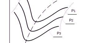
As the magnetic flux increases, the steel of the magnetic circuit has the property of saturation, therefore the magnetic characteristic of the synchronous generator is nonlinear. This characteristic as the dependence of the magnetic flux on the excitation current Ф = f(IВ) or Ф = f(ФВ) can be constructed by calculation or determined experimentally. It looks like shown in Figure 2.
Figure 2. Magnetic characteristic of S.G.
Usually S.G. designed so that at the nominal value of the magnetic flux F, the magnetic circuit is saturated. In this case, the “ab” section of the magnetic characteristic corresponds to the MMF when overcoming the air gap of 2Fsigma, and the “vc” section corresponds to overcoming the magnetic resistance of the magnetic core steel. Then the ratio can be called the saturation coefficient of the magnetic circuit as a whole.
Idle speed of synchronous generator
If the stator winding circuit is open, then in S.G. There is only one magnetic field - created by the MMF of the field winding. The sinusoidal distribution of the magnetic field induction, necessary to obtain the sinusoidal EMF of the stator winding, is ensured: - in salient-pole S.G. the shape of the rotor pole pieces (under the middle of the pole the gap is smaller than under its edges) and the bevel of the stator slots. - in non-salient pole S.G. – by the distribution of the field winding along the rotor slots under the middle of the pole, the gap is smaller than under its edges and the bevel of the stator slots. In multi-pole machines, stator windings with a fractional number of slots per pole and phase are used.
Figure 3. Ensuring that the excitation magnetic field is sinusoidal
Since the EMF of the stator winding E10 is proportional to the magnetic flux ФО, and the current in the excitation winding IVO is proportional to the MMF of the excitation winding FVO, it is easy to construct the dependence: E0 = f(IВО) identical to the magnetic characteristic: Ф = f(FВО). This dependence is called the idle speed characteristic (H.H.H.) S.G. It allows you to determine the parameters of the S.G. and build its vector diagrams. Usually H.H.H. are constructed in relative units e0 and iBO, i.e. the current value of the quantities is referred to their nominal values
In this case, H.H.H. called normal characteristic. The interesting thing is that normal X.H.H. for almost all S.G. are the same. In real conditions, H.H.H. starts not from the origin of coordinates, but from a certain point on the ordinate axis, which corresponds to the residual EMF e RES., caused by the residual magnetic flux of the magnetic core steel.
Figure 4. Idle characteristics in relative units
Schematic diagrams of excitation S.G. with excitation a) and self-excitation b) are shown in Figure 4.
Figure 5. Schematic diagrams of excitation S.G.
Magnetic field S.G. under load.
To load S.G. or increase its load, it is necessary to reduce the electrical resistance between the phase terminals of the stator winding. Then currents will flow through the closed circuits of the phase windings under the influence of the EMF of the stator winding. If we assume that this load is symmetrical, then the phase currents create the MMF of the three-phase winding, which has an amplitude
and rotates along the stator with a rotation speed n1 equal to the rotor speed. This means that the MMF of the stator winding F3F and the MMF of the excitation winding FB, stationary relative to the rotor, rotate at the same speeds, i.e. synchronously. In other words, they are motionless relative to each other and can interact. At the same time, depending on the nature of the load, these MMFs can be differently oriented relative to each other, which changes the nature of their interaction and, consequently, the operating properties of the generator. Let us note once again that the effect of the MMF of the stator winding F3Ф = Fa on the MMF of the rotor winding FB is called the “armature reaction”. In non-salient-pole generators, the air gap between the rotor and stator is uniform, therefore the induction B1 created by the MMF of the stator winding is distributed in space like the MMF F3Ф = Fa sinusoidally, regardless of the position of the rotor and the field winding. In salient-pole generators, the air gap is uneven due to both the shape of the pole pieces and the interpole space filled with copper field windings and insulating materials. Therefore, the magnetic resistance of the air gap under the pole pieces is significantly less than in the region of the interpolar space. Rotor pole axis S.G. they call it the longitudinal axis d - d, and the axis of the interpolar space is called the transverse axis S.G. q - q. This means that the induction of the stator magnetic field and the graph of its distribution in space depend on the position of the MMF wave F3F of the stator winding relative to the rotor. Let us assume that the amplitude of the MMF of the stator winding F3Ф = Fa coincides with the longitudinal axis of the machine d - d, and the spatial distribution of this MMF is sinusoidal. Let us also assume that the excitation current is zero Iо = 0. For clarity, let us depict in the figure a linear scan of this MMF, from which it can be seen that the induction of the stator magnetic field in the region of the pole piece is quite large, and in the region of the interpolar space it sharply decreases to almost zero from - due to high air resistance.
Figure 6. Linear scan of the MMF of the stator winding along the longitudinal axis.
Such an uneven distribution of induction with amplitude B1dmax can be replaced by a sinusoidal distribution, but with a smaller amplitude B1d1max. If the maximum value of the stator MMF F3Ф = Fa coincides with the transverse axis of the machine, then the magnetic field pattern will be different, as can be seen from the linear scan of the machine MMF.
Figure 7. Linear scan of the MMF of the stator winding along the transverse axis.
Here, too, the amount of induction in the area of the pole tips is greater than in the area of the interpolar space. And it is quite obvious that the amplitude of the main harmonic of the stator field induction B1d1 along the longitudinal axis is greater than the amplitude of the field induction B1q1 along the transverse axis. The degree of reduction in induction B1d1 and B1q1, which is caused by the unevenness of the air gap, is taken into account using the coefficients:
They depend on many factors and, in particular, on the sigma/tau ratio (sorry there is no symbol) (the relative size of the air gap), on the ratio
(pole overlap coefficient), where VP is the width of the pole piece, and other factors.
Principle of operation
The excitation flow, rotating at a certain frequency, created by the rotor, crosses the turns of the stator winding, it induces in phases with a variable EMF, changing with a frequency determined by the formula:
f1=pn2/60.
When the stator is connected to a load, the current in the winding creates a magnetic field that rotates at the same speed as the rotor. The magnetomotive force of the field and stator windings, and the resulting rotating magnetic field, creates the resulting magnetic flux.
Comparison of synchronous and asynchronous motors
In conclusion, we can summarize what are the main differences between asynchronous (AM) and synchronous (SD) motors.
Let's highlight the basic points:
- The rotor of asynchronous motors does not require current supply, and the induction at the poles depends on the stator magnetic field.
- The IM revolutions under load lag by 1-8% from the rotation speed of the stator field. In SD, the number of revolutions is the same.
- The “synchronizer” has an excitation winding.
- Structurally, the rotor of an SD is a magnet: permanent, electric. In IM, the magnetic field in the rotor mechanism is induced using induction.
- A synchronous machine does not have a starting torque, so an asynchronous start is needed to achieve synchronization.
- “Synchronizers” are used in cases where it is necessary to ensure continuity of the production process and there is no need for frequent restarts. IMs are needed where high starting torque is required and frequent stops occur.
- The LED needs an additional current source.
- “Asynchronous” wear out more slowly, because in their design there are no slip rings with brushes.
- As a rule, blood pressure is characterized by a non-round number of revolutions, while SD is characterized by a rounded number.
High power synchronous machines - design features
Due to the use of a significant amount of power, the synchronous installation is subjected to significant mechanical stress, as well as electromagnetic load, as a result of which significant heating of various parts of the machines occurs, for which it is necessary to perform intensive cooling of the machine. To maintain certain overall dimensions, to obtain the required power value, machines are made with various features that dictate the division of machines into several types, these are: turbogenerators, hydrogenerators, diesel generators, synchronous compensators, synchronous motors.
Turbogenerators
The design of the machine is made with a horizontal axis and operates through the use of a turbine; the rotor is necessarily non-salient-pole. The shaft rotation speed differs in the maximum possible number of rotation speeds and is 3000 rpm.
Due to the fact that the machine has only two poles, its structural part is characterized by reduced dimensions and weight. When using such a unit at nuclear power plants, they use machines with a shaft speed of 1500 rpm, with 4 poles, the diameter of the rotor is less than the length of its active part. The system used for cooling uses surface and indirect forced air cooling, sometimes indirect hydrogen or water and oil cooling are used.
Hydro generators
The operation of the hydrogenerator is carried out using a hydraulic turbine with a low number of shaft revolutions from 50 to 500 rpm. The salient pole rotor is characterized by the presence of a large number of pole pairs. Its diameter for some types of hydrogenerators can reach up to 16 m, while its length is only 1.75 m. Its power reaches 640 MV*A.
The shaft can be positioned vertically. The hydrogenerator and the turbine are combined by a single rotor shaft; an exciter, a subexciter and a synchronous generator can also be installed on it, which powers the electric motors designed to regulate the turbine. The main force in the machine falls on the support bearing; it is able to withstand the weight of the rotors of all equipment, dynamic forces and water pressure applied to the turbine blades. The cooling system in devices of this type is carried out by washing the capsule, which encloses the elements of a synchronous unit united by one shaft.
Synchronous compensator
The machine generates reactive power and operates in idling motor mode, using an active network load. The salient pole design typically has up to eight pole pairs. The rotor is made lightweight, since there is no load on the shaft. A sealed machine design is often used, without the compensator shaft coming out; the cooling system works by using hydrogen pumped inside at high pressure.
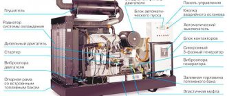
Diesel generator
The machine has a salient pole rotor in its design and implies a horizontal shaft installation. A special feature is the use of one support bearing; the generator shaft bearing is used as the second support. The exciter is installed on the same shaft as them.
Write comments, additions to the article, maybe I missed something. Take a look at the site map, I will be glad if you find anything else useful on my site. All the best.
Advantages and disadvantages
The advantages of such an electric motor include:
- high cosφ, approaching 1 in value, which is significantly superior to asynchronous electric motors;
- higher mechanical strength due to the design features of the electric motor;
- the dependence of torque on voltage is linear, not quadratic, so the oscillations of the electric motor are proportionally reduced;
- there is a constant speed on the electric motor shaft, independent of the applied load;
- can be used to reduce the reactive component in the network.
Among the disadvantages of synchronous electric motors are:
- complex design;
- more complex launch;
- the need to use auxiliary devices and blocks;
- such electric motors are more difficult to regulate in terms of speed;
- repairs and maintenance will also cost more than asynchronous electric motors.