Safety rules during maintenance
Before carrying out maintenance of any complexity, it is necessary to ensure the safety of operating personnel. All maintenance work (except for checking operating conditions) is carried out with complete removal of voltage from the equipment.
The direct executor must ensure that spontaneous or erroneous supply of voltage to the serviced electric motor is blocked. To do this, it is necessary to block the voltage supply, and hang a poster on the lever of the switching mechanism: “Do not turn on, people are working!”
Electric motor diagnostics
Diagnostics means measuring certain parameters of the electric motor in operating mode and without voltage.
The following parameters are usually measured:
- Temperature
. This is a universal parameter that can say a lot about the condition of the engine. Operational measurement of the body temperature is carried out using a pyrometer or thermal imager. In some cases, a temperature sensor must be installed in the engine to provide constant temperature control. Read more about temperature conditions and electric motor overheating here. - Current
_ By comparing the rated (operating) current with the measured one, you can assess the condition of the electric motor and the drive as a whole. - Vibration
. When vibration levels increase, mechanical damage to the engine may occur. This parameter is assessed using special equipment.
With the motor de-energized, the insulation resistance is measured using a megohmmeter.
Based on the results of the listed measurements and their comparison with the nominal values, we can conclude that repairs are necessary.
Rules for the technical operation of DC machines
During maintenance, the following operations are performed: - check the operation of the machine under load and at idle. If the control circuit does not have an ammeter, the load is measured using a clamp meter. If a motor overload is detected, immediate measures are taken to reduce the load to the nominal value. If the engine operates at maximum speeds due to a weakening magnetic field, the rotation speed should be periodically measured with a tachometer. Operating the engine at an increased speed above the rated speed is unacceptable. — check the heating and condition of the rolling bearings; — check the fastening of the engine to the foundation plate by lightly hitting the nut. If necessary, tighten the nuts; — inspect the fit of couplings and pulleys. A loose fit is detected by the presence of a coating of red powder from contact corrosion that occurs during mutual movement of mating parts; — inspect the commutator, brushes and brush holders. When inspecting the commutator, check that there is sufficient cutting of mica between the commutator plates, the protrusion of which above the plates may cause sparking of the brushes; For small DC EMs, the collectors are made of plastic. The insulation between the collector plates is cut into them to a depth of 1.5 mm. However, some types of small machines, in which the collectors are assembled from phlogotype mica with a hardness less than that of copper, do not make slots between the collector plates. When checking, pay attention to the lack of tightening of the copper plates with brushes. The tension of the copper “visors” is easily removed with hard nylon brushes. If streaks are found on the surface of the commutator, the brushes are replaced. Brush holders with all structural elements must be in good working order. Periodically collector. The brush apparatus and the motor inside and outside are blown with dry compressor air at a pressure of 0.2 MPa - the motor connection is inspected. The manifestation of weak contacts is detected when the insulation overheats and hardens with a change in color. The causes of weak contacts may be insufficient tightening of the contacts during connection, unsoldering or poor crimping of the tips; — check the serviceability of the engine grounding; — systematically check the tightness of the mounting bolts of the panels and flanges by tapping; — measure the insulation resistance of the windings in accordance with the requirements of local instructions. The measurement results are recorded in a special journal.
Motor Maintenance
Electric motor maintenance is a planned event for which time must be allocated and a person responsible must be assigned. As a rule, engine maintenance is carried out at the site of its installation, and the following actions are performed:
- cleaning the engine housing from dirt
- checking the mechanical fastenings of the electric motor and the drive as a whole
- checking the integrity and reliability of fastening of the cooling fan impeller (independent fan)
- opening the motor terminal box, inspection, revision and pulling of power terminals
- bearing lubrication
- inspection of the integrity of the power cable and grounding
In addition, when carrying out maintenance, it is necessary to check the engine power system - terminals, contactors, protection devices, etc.
With high-quality regular maintenance of an asynchronous motor, it can operate without repair for decades. However, due to a number of reasons (for example, mismatch of power supply parameters or deterioration of operating conditions), repairs may be required.
Maintenance of a three-phase asynchronous motor with a wound rotor lesson presentation
Slide 1
Maintenance of 3-phase asynchronous electric motor with wound rotor
Slide 2
Purpose of an asynchronous electric motor with a wound rotor Three-phase asynchronous motors convert electrical energy into mechanical energy. They are called asynchronous because the rotor speed lags behind the rotation speed of the stator magnetic field.
Slide 3
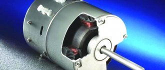
The motor consists of a stator (stationary part) and a rotor (rotating part). The rotor is placed inside the stator. There is an air gap between the rotor and stator. The stator consists of a frame and a core with a three-phase winding. The main purpose of the stator winding is to create a rotating magnetic field in the machine.
Slide 4
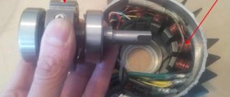
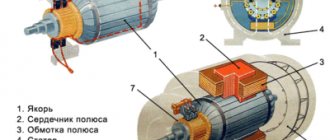
The rotor is assembled from sheets of steel, pressed and turns of the phase winding are placed into it, which are connected in a star pattern. The ends of each phase are connected to slip rings, which are located on the rotor shaft. In turn, the slip rings come into contact with graphite brushes, which have leads into a box on the body to allow connection of additional resistance. 1 - stator; 2 - rotor; 3 — slip rings with brushes; 4 - starting rheostat Phase rotor of an asynchronous motor: 1 - rotor core; 2 — rotor winding; 3 - slip ring
Slide 5
Electric motor rotor
Slide 6
Operating principle. . Current flowing through a conductor creates a magnetic field around it. When the stator winding is powered by a three-phase current, a rotating magnetic field is created, which, crossing the conductors of the rotor winding, induces E.M.F. in them. (according to the law of electromagnetic induction). Since the rotor winding circuit is closed, currents I 2 will flow in its conductors. When currents interact with a rotating magnetic field, electromagnetic forces F arise, directed (according to the left-hand rule) in the direction of rotation of the stator field. A torque is created, the rotor starts to move and rotates in the same direction as the stator’s magnetic field, always lagging behind it.
Slide 7
Repair, installation and maintenance Preparing machines for installation includes the following technical operations: - external inspection; — cleaning of foundation slabs and frame feet; — washing the foundation bolts with white spirit and checking the quality of the threads (running the nuts); — inspection of the condition of bearings; — checking the gaps between the cover and the plain bearing shell, the shaft and the bearing seal, measuring the gaps between the plain bearing shell and the shaft; — checking the air gap between the active part of the steel of the rotor and stator; — checking that the rotor rotates freely and that the fans do not touch the covers; — checking the insulation resistance of all windings with a megger.
Slide 8
Maintenance The main purpose of maintenance (TO) is prevention and timely detection of faults. IM maintenance includes the following operations: External inspection and assessment of the condition of the mechanical part External inspection and assessment of the condition of the electrical part Measurements and tests
Slide 9
Repair is a set of operations to restore the serviceability or performance of electric motors. Faults and damage to electrical machines cannot always be detected by external inspection and can only be determined after appropriate measurements and tests.
Slide 10
The number of pre-repair operations to identify faults in electrical machines includes: -measurement of the insulation resistance of the windings (to determine the degree of its moisture); electrical insulation strength test; checking at idle speed of the machine the integrity of the bearings, the magnitude of the axial run of the rotor, the correct fit of the brushes to the slip rings, the magnitude of vibration, determining the size of the gaps between the rotating and stationary parts of the machine, etc.
Slide 11
Maintenance. Clean the motor housing from dust and dirt, disconnect the motor from the power wires and grounding. Disconnect the wires from the starting rheostat. Remove the engine from its installation location and disassemble it. Clean the windings, measure the insulation resistance, and dry the windings if necessary. Check the condition of the slip rings, clean and polish them if necessary. Adjust the brush mechanism, replace the brushes if necessary. Wash the bearings, check their technical condition and replace if necessary. Repair or replace damaged winding lead wires and terminal box terminal block. Assemble the engine, lubricate the bearings, test the engine at idle. If necessary, paint the engine. Install the engine on the workplace, adjust its alignment with the working machine and test it under load.
Slide 12
Major repairs include all routine repair operations and in addition: - change the stator and rotor windings - partially or completely; - change the rotor shaft; - balance the rotor; - change the fan and bearing shields; -clean the electric motor from the inside by disassembling, assembling and testing it under load.
Slide 13
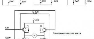
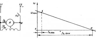
Connection diagram for an asynchronous electric motor Starting an asynchronous motor with a phase-wound rotor FU - fuse K - main contactor - connects the stator winding to three-phase voltage. R d - additional resistor Starting a motor with a wound rotor (slip rings) is carried out by connecting the stator winding to the network with additional resistors r d previously introduced into the rotor circuit. As the engine accelerates, the resistors rd are removed using the engine and at the end of the start, the resistor resistance goes to zero, and the rotor winding becomes short-circuited, as in a motor with a squirrel-cage rotor. The introduction of additional resistance into the rotor circuit when starting a motor with a wound rotor makes it possible to increase the starting torque up to the maximum value and at the same time significantly reduce the starting current.
Electric motor repair
In addition to maintenance, if necessary or according to plan, current, medium and major repairs of the electric motor can be carried out. The purpose of repair is to restore the performance or functionality of the engine.
During repairs, based on previously performed inspections and diagnostics, the following activities can be performed:
- bearing replacement
- rotor balancing
- fan impeller replacement
- stator winding rewinding
Other useful materials:
About electric motors with brakes Forced cooling of the electric motor How to choose the right electric motor
Inspection of the electrical component of an asynchronous electric motor.
When inspecting the electrical component, first of all it is necessary to check the condition of the stator terminals. They must be well insulated, and their tips must be clean, without the slightest soot or oxide. Attention should also be paid to the terminal block, which should be intact without any visible damage. Current-collecting rotor brushes must be perfectly smooth, without chips or cracks, and their size must be at least 5 millimeters. They should fit snugly against the slip rings. The slip rings must be free of dust and dirt. At the end, it is recommended to check the condition of the grounding conductor and its fastening.