History of the invention of the electric current generator
Russian scientist E.H. Lenz back in 1833. pointed out the reversibility of electric machines: the same machine can work as an electric motor if it is powered with current, and can serve as a generator of electric current if its rotor is driven into rotation by some engine, for example a steam engine. In 1838 Lenz, one of the members of the commission for testing the action of the Jacobi electric motor, experimentally proved the reversibility of the electric machine.
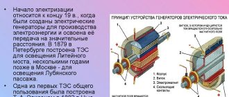
The first electric current generator, based on the phenomenon of electromagnetic induction, was built in 1832. by Parisian technicians the Pixin brothers. This generator was difficult to use, since it was necessary to rotate a heavy permanent magnet so that an alternating electric current would arise in two wire coils fixed motionless near its poles. The generator was equipped with a device for rectifying the current. In an effort to increase the power of electric machines, inventors increased the number of magnets and coils. One of these machines, built in 1843, was the Emil Stehrer generator. This machine had three strong moving magnets and six coils that rotated by hand around a vertical axis. Thus, at the first stage of the development of electromagnetic current generators (before 1851), permanent magnets were used to produce a magnetic field. At the second stage (1851-1867), generators were created in which permanent magnets were replaced with electromagnets to increase power. Their winding was powered by current from an independent small current generator with permanent magnets. A similar machine was created by the Englishman Henry Wilde in 1863.
During the operation of this machine, it turned out that generators, while supplying electricity to the consumer, can simultaneously supply current to their own magnets. It turned out that the cores of electromagnets retain residual magnetism after turning off the current. Thanks to this, the self-excited generator produces current even when it is started from a state of rest. In 1866-1867 a number of inventors received patents for self-excited machines.
In 1870 Belgian Zenob Gramm, who worked in France, created a generator that was widely used in industry. In his dynamo, he used the principle of self-excitation and improved the ring armature, invented back in 1860 by A. Pacinotti.
In one of Gram's first machines, a ring armature mounted on a horizontal shaft rotated between the pole pieces of two electromagnets. The armature was driven into rotation through a drive pulley, the windings of the electromagnets were connected in series with the armature winding. The Gram generator provided a direct current, which was discharged using metal brushes sliding along the surface of the commutator. At the Vienna International Exhibition in 1873. two identical Gram machines were demonstrated, connected by wires 1 km long. One of the machines was driven by an internal combustion engine and served as a generator of electrical energy. The second machine received electrical energy through wires from the first and, working like an engine, drove the pump. It was a spectacular demonstration of the reversibility of electrical machines, discovered by Lenz, and a demonstration of the principle of energy transfer over distance.
Before the connection between electricity and magnetism was discovered, electrostatic generators were used, which operated based on the principles of electrostatics. They could produce high voltage, but had little current. Their work was based on the use of electrified belts, plates and disks to transfer electrical charges from one electrode to another.
The charges were generated using one of two mechanisms:
- Electrostatic induction
- Triboelectric effect, in which an electric charge arose due to mechanical contact of two dielectrics
Due to low efficiency and difficulties in insulating machines that generate high voltages, electrostatic generators were of low power and were never used to generate electricity on an industrial scale. Examples of machines of this kind that have survived to this day are the electrophore machine and the Van de Graaff generator.
Physics report “Generator”
Generator
History of appearance
The first generator was built in 1832 by Parisian technicians, the Pixi brothers. This generator was difficult to use, since it was necessary to rotate a heavy permanent magnet so that an alternating electric current would arise in two wire coils fixed motionless near its poles. The generator was equipped with a device for rectifying the current. In an effort to increase the power of electric machines, inventors increased the number of magnets and coils. One of these machines, built in 1843, was the Emil Stehrer generator. This machine had three strong moving magnets and six coils that rotated by hand around a vertical axis. Thus, at the first stage of the development of electromagnetic current generators, permanent magnets were used to produce a magnetic field. At the second stage, generators were created in which, to increase power, permanent magnets were replaced by electromagnets. Their winding was powered by current from an independent small current generator with permanent magnets.
During the operation of this machine, it turned out that generators, while supplying electricity to the consumer, can simultaneously supply current to their own magnets. It turned out that the cores of electromagnets retain residual magnetism after turning off the current. Thanks to this, the self-excited generator produces current even when it is started from a state of rest.
In 1870, the Belgian Zenob Gramm, working in France, created a generator that was widely used in industry. In his dynamo, he used the principle of self-excitation and improved the ring armature, invented back in 1860 by A. Pacinotti.
In one of Gram's first machines, a ring armature mounted on a horizontal shaft rotated between the pole pieces of two electromagnets. The armature was driven into rotation through a drive pulley, the windings of the electromagnets were connected in series with the armature winding. The Gram generator provided a direct current, which was discharged using metal brushes sliding along the surface of the commutator. Which generated a current while driving.
Dynamo machine
The first dynamo was invented by A. Jedlik in 1827. He formulated the dynamo concept six years earlier than Siemens, but did not patent it.
A dynamo or dynamo is an obsolete name for a generator used to generate direct electric current from mechanical work. The dynamo was the first electrical generator to be used in industry. Later it was replaced by alternating current generators, since alternating current is easier to transform.
A dynamo consists of a coil of wire rotating in a magnetic field created by a stator. The rotational energy, according to Faraday's law, is converted into alternating current, but since the first inventors of the dynamo did not know how to work with alternating current, they used a commutator to invert the polarity. The result was a pulsating current of constant polarity.
Other electrical generators using rotation
Without a commutator, a dynamo is an example of an alternator. With an electromechanical commutator, the dynamo is a classic DC generator. The alternator must always have a constant rotor speed and be synchronized with other generators in the power distribution network. A DC generator can operate at any rotor frequency within its permissible limits, but produces direct current.
DC generators are sources of direct current that convert mechanical energy into electrical energy. The generator armature is driven into rotation by some kind of engine, which can be electric internal combustion engines, etc. DC generators are used in those industries where, according to production conditions, direct current is necessary or preferable (in the metallurgical and electrolysis industries, in transport, on ships, etc.). They are also used in power plants as exciters of synchronous generators and direct current sources.
Recently, in connection with the development of semiconductor technology, rectifier units are often used to produce direct current, but despite this, direct current generators continue to be widely used.
The switch is designed to switch the current in the primary winding of the ignition coil in accordance with the control pulses of the Hall sensor D-R.
Hall Sensor
The magnetoelectric Hall sensor got its name from E. Hall, an American physicist who discovered an important galvanomagnetic phenomenon in 1879. The advantages of this switch are high reliability and durability, small dimensions, and the disadvantages are constant energy consumption
The Hall sensor has a slot design. On one side of the slot there is a semiconductor through which current flows when the ignition is turned on, and on the other side there is a permanent magnet. A steel cylindrical screen with slots fits into the sensor slot. When the screen rotates, when its slits are in the sensor slot, the magnetic flux acts on the semiconductor with current flowing through it and the control pulses of the Hall sensor are fed to the switch, in which they are converted into current pulses in the primary winding of the ignition coil.
a - there is no magnetic field, the supply current flows through the semiconductor - AB;
b - under the influence of a magnetic field - N
Hall EMF appears - EF;
c - Hall sensor
The easiest way to check the Hall sensor is to replace it with a known good one, but you can also use an ordinary voltmeter (tester). For a working Hall sensor, the voltmeter, switched on to measure DC voltage and connected to the output of the sensor, should sharply change readings from approximately 0.4 V to a value no more than 3 V different from the supply voltage as the shaft of the distribution sensor rotates.
MHD generator
A magnetohydrodynamic generator directly generates electricity from the energy of a plasma or other similar conducting medium (for example, a liquid electrolyte) moving through a magnetic field without the use of rotating parts. The development of generators of this type began because its output produces high-temperature combustion products, which can be used to heat steam in combined-cycle power plants and thus increase the overall efficiency. The generator is a reversible device, that is, it can also be used as an engine.
Alternator
An alternator is an electromechanical device that converts mechanical energy into alternating current electrical energy. Most alternators use a rotating magnetic field.
The large two-phase alternating current generator was built by British electrician James Edward Henry Gordon in 1882.
The operating principle of the generator is based on the phenomenon of electromagnetic induction.
The operation of the generator is based on the effect of electromagnetic induction. If a coil, for example, made of copper wire, is penetrated by a magnetic flux, then when it changes, an alternating current appears at the coil terminals
electrical voltage. Conversely, to generate a magnetic flux, it is enough to pass an electric current through the coil. Thus, to produce an alternating electric current, a coil is required through which a direct electric current flows, forming a magnetic flux, called the field winding, and a steel pole system, the purpose of which is to supply the magnetic flux to the coils, called the stator winding, in which an alternating voltage is induced. These coils are placed in the grooves of the steel structure, the magnetic circuit (iron package) of the stator. The stator winding with its magnetic core forms the generator stator itself, its most important stationary part, in which electric current is generated, and the excitation winding with the pole system and some other parts (shaft, slip rings) forms the rotor, its most important rotating part. The field winding can be powered from the generator itself. In this case, the generator operates on self-excitation. In this case, the residual magnetic flux in the generator, i.e., the flux that is formed by the steel parts of the magnetic circuit in the absence of current in the field winding, is small and ensures self-excitation of the generator only at too high rotation speeds. Therefore, such an external connection is introduced into the generator set circuit, where the field windings are not connected to the battery, usually through a generator set health lamp. The current flowing through this lamp into the excitation winding after turning on the ignition switch provides the initial excitation of the generator. The strength of this current should not be too high so as not to discharge the battery, but not too low, because in this case the generator is excited at too high speeds, so manufacturers stipulate the required power of the control lamp - usually 2...3 W
DC generator
A DC generator converts mechanical energy into electrical energy. Depending on the methods of connecting the field windings to the armature, generators.
DC generators are sources of direct current that convert mechanical energy into electrical energy. The generator armature is driven into rotation by some kind of engine, which can be electric internal combustion engines, etc. DC generators are used in those industries where, according to production conditions, direct current is necessary or preferable (in the metallurgical and electrolysis industries, in transport, on ships, etc.). They are also used in power plants as exciters of synchronous generators and direct current sources.
Recently, in connection with the development of semiconductor technology, rectifier units are often used to produce direct current, but despite this, direct current generators continue to be widely used.
DC generators are produced with powers ranging from several kilowatts to 10,000 kW.
Types of generators
1. Independent excitation generator. In a generator with independent excitation, the excitation current does not depend on the armature current, which is equal to the load current. Typically the excitation current is small.
2. Self-excited generator. A self-excited generator is a resonant amplifier with a feedback circuit through which part of the output oscillation voltage is fed back to the input - to the control grid. The principle of self-excitation is as follows. If a control voltage is applied to the amplifier tube, increased oscillations will occur in the anode circuit.
3. Sequential excitation generators. For series excitation generators, the excitation current is equal to the armature current.
4. Mixed excitation generators. A generator with mixed excitation has two excitation windings: the main (parallel) and auxiliary (series) windings. The presence of two windings when they are switched on in agreement makes it possible to obtain an approximately constant generator voltage when the load changes.
5. Parallel excitation generator. In a parallel excitation generator, the excitation winding is powered by its own armature. The electromotive force in the armature appears as a result of self-excitation of the machine, which occurs under the influence of residual magnetism in the poles and yoke of the stator. In order for a magnetic flux of residual magnetism to appear in a machine, it must be magnetized at least once by passing current through the excitation winding from an external source. Since the excitation winding is connected to the armature, the EMF creates a small current in it. This current, flowing through the field winding, increases the magnetic flux of the poles, which in turn increases the EMF in the armature. An increase in EMF causes an increase in the current in the field winding, which further increases the magnetic flux of the poles and the EMF induced in the armature, which causes a further increase in the field current.
Car generator
A car generator is a device that converts the mechanical energy of rotation of a car engine into electrical energy. A car generator is used to charge the car battery, as well as to power regular electrical consumers such as the on-board computer, side lights and others. Car generators are subject to high reliability requirements, since the generator ensures uninterrupted operation of most components of a modern car.
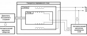
Modern cars use valve generators. These are synchronous three-phase AC electrical machines, which - both domestic and foreign - have very similar designs and differ, if we leave aside the workmanship, only in dimensions, location of connecting points and individual components.
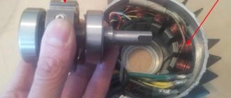
The stator of a car generator is a ring with 18 windings: 6 for each phase. Each winding has 5 turns.
Slip rings are installed on the rotor shaft, to which voltage from the battery is supplied using brushes. As a result, a current begins to flow through the rotor field winding, which creates a magnetic field.
After starting the engine, the rotor is set into rotation, and the rotating magnetic field of the rotor begins to cross the stator windings, resulting in an electromotive force and alternating current in each winding.
With the help of a rectifier unit, the alternating current of the stator windings is converted into direct current. The rectifier unit consists of two aluminum plates, into which three diodes are pressed.
The voltage generated by the generator depends to the greatest extent on the rotor speed and the current in the field windings.
For normal operation of consumers, the voltage generated by the generator must be within 13.7 - 14.5 V.
At high crankshaft speeds, the voltage generated by the generator increases. In order to keep the voltage supplied by the generator within the range of 13.7 - 14.5 V, voltage relay regulators are used. If the voltage exceeds the permissible 14.5 V, the relay regulator interrupts the circuit of the rotor field winding and no current flows through the field winding. As a result, the voltage supplied by the generator begins to drop, and when it again falls into the range of 13.7 - 14.5 V, the supply of current to the rotor field winding is resumed.
The housing (5) and the front cover of the generator (2) serve as supports for the bearings (9 and 10), in which the armature (4) rotates. Voltage from the battery is supplied to the armature field winding through brushes (7) and slip rings (11). The anchor is driven by a V-belt through a pulley (1). When starting the engine, as soon as the armature begins to rotate, the electromagnetic field it creates induces an alternating electric current in the stator winding (3). In the rectifier block (6) this current becomes constant. Next, the current through the voltage regulator combined with the rectifier unit enters the vehicle's electrical network to power the ignition system, lighting and alarm systems, instrumentation, etc. The battery will be connected to these devices and will begin to recharge a little later, as soon as the electricity generated by the generator set is supplied. will be sufficient to ensure uninterrupted functioning of all consumers.
The operating principle of any electric generator
The operating principle of any electric generator is based on the phenomenon of electromagnetic induction. Electromagnetic induction converts the mechanical energy of the engine (rotation0 into electrical energy. The principle of magnetic induction: if a frame rotates uniformly in a uniform magnetic field B, then a variable E.M.F. appears in it, the frequency of which is equal to the frequency of rotation of the frame. Will we rotate frame in a magnetic field, or a magnetic field around the frame, or a magnetic field inside the frame, the result will be the same - E.M.F., changing according to a harmonic law.
Now let's talk about asynchronous and synchronous generators in more detail.
Synchronous electric generator
A synchronous electric generator is a synchronous machine operating in generator mode in which the rotation frequency of the stator magnetic field is equal to the rotor rotation frequency. A rotor with magnetic poles creates a rotating magnetic field, which, crossing the stator winding, induces an emf in it. In a synchronous generator, the rotor is made in the form of a permanent magnet or electromagnet.
The number of rotor poles can be two, four, etc., but a multiple of two. In household power plants, as a rule, a rotor with two poles is used, which determines the rotation speed of the power plant engine of 3000 rpm. The rotor, when starting the power plant, creates a weak magnetic field, but with increasing speed, the EMF in the field winding also increases. The voltage from this winding is supplied to the rotor through an automatic regulation unit (AVR), controlling the output voltage by changing the magnetic field. For example, a connected inductive load demagnetizes the generator and reduces the voltage, and when a capacitive load is connected, the generator is biased and the voltage increases. This is called the "anchor reaction".
To ensure stability of the output voltage, it is necessary to change the magnetic field of the rotor by regulating the current in its winding, which is provided by the AVR unit. The advantage of such generators is the high stability of the output voltage, but the disadvantage is the possibility of current overload, since if the load is too high, the regulator can excessively increase the current in the rotor winding. Another disadvantage of a synchronous generator is the presence of a brush assembly, which sooner or later will have to be serviced. Thanks to this adjustment method, regardless of changes in load current and power plant engine speed, the stability of the generator output voltage remains very high, approximately ±1%.
History of the creation and development of the alternator
Economics, 15:19 07 May 2009
Tyumen. The first multi-pole synchronous alternating current generator was created in 1832 by an unknown inventor. Since then, the problem of scientists has been to create the most efficient switching devices, but while alternating current has not been used very widely, the development of generators has been rather sluggish. Moreover, obtaining alternating current has never been a particularly difficult problem, because any generators in the winding create alternating current.
An important stage in the development of alternating current generators was the creation of the Wilde generator, which was based on two slip rings and a separate magnetic exciter. Wilde later developed a generator that did not use separate exciters. The generator armature was a double-T-shaped steel core with two types of winding. The main disadvantage of the Wilde generator was the excessive loss of steel during generator operation, due to which the generator could not operate for a long time.
The next stage in the development of alternating current generators was the Yablochkov candle, which began to be used in lighting residential premises. It was the first attempts to use alternating current in domestic conditions that led to the development of current generation technologies and to the improvement of existing generators. Yablochkov developed several versions of alternating current generators designed for different numbers of candles, but the load on the cores remained a problem, which did not allow the generators to operate for a long time. The problem was the technology of that time, which did not allow the creation of armatures more suitable for generators. Manufacturers solved this issue in different ways, even going so far as to create generators without cores, but the efficiency of such machines remained low.
The final stage in the development of alternating current generators was the creation of a two-phase generator with coil windings at Paddington station. The machine weighed 18 tons, despite the fact that its power was 150 kW. However, at that time it was the most advanced and efficient alternating current generator, which made it possible to supply residential buildings with electricity and create an effective lighting system in them. At the present stage, it is quite possible to buy diesel power plants, which more efficiently and competently solve the problems of creating an electrical system for buildings.
Asynchronous electric generator
An asynchronous electric generator is an asynchronous machine (motor) operating in braking mode, the rotor of which rotates ahead, but in the same direction as the magnetic field of the stator. Depending on the type of winding, the rotor can be short-circuited or phase.
The rotating magnetic field created by the auxiliary stator winding induces a magnetic field on the rotor, which, rotating with the rotor, induces an emf in the working stator winding, as well as in a synchronous generator. The rotating magnetic field always remains unchanged and is not adjustable, as a result of which the voltage and frequency at the generator output depend on the rotor speed, and therefore on the stability of the power plant engine.
Despite the ease of maintenance, low sensitivity to short circuits and low cost, asynchronous generators are used quite rarely, as there are a number of disadvantages: an asynchronous generator always consumes a magnetizing current of significant strength, so its operation requires a source of reactive power (capacitors), depending on the active - inductive nature of the load; unreliability of work in extreme conditions; excitation of an asynchronous generator depends on random factors and occurs, as a rule, at a speed greater than or equal to synchronous; dependence of the output voltage and current frequency on the stability of the engine, etc.
Generator operation
After the pistons accelerate to the starting frequency, fuel is supplied to the first cylinder, combustion occurs and the expansion of the resulting gases begins. At this moment, air compression occurs in the second cylinder.
When the outer piston in the first cylinder of the exhaust valves is reached, exhaust gases begin to be released.
When the internal piston in the first cylinder of the purge ports is reached, the purge process begins. In this LG, the blowing is direct-flow, which ensures the lowest residual gas coefficient. This, in turn, increases the mass charge of air in the cylinder, which leads to complete combustion of fuel, etc. At this moment the pistons reach their extreme positions.
The expansion of gases in the second cylinder sets the pistons of the first cylinder in motion. The internal piston reaches the scavenging ports and closes them while the exhaust ports are still open. This leads to a loss of air mass charge in the cylinder, but this loss can be neglected due to the low coefficient of residual gases in the cylinder. The external piston reaches the exhaust ports, blocks them, and thereby ensures the compression process in the first cylinder, while expansion occurs in the second. And the cycle repeats.
Generator device
The main parts of any generator are: a system of magnets (or, most often, electromagnets) that create a magnetic field, and a system of conductors that cross this magnetic field. When a magnetic field is passed through the coil, the magnetic flux will force the free electrons to move to the ends of the conductor. Such a displacement of negatively charged particles becomes a source of electromotive force - EMF (voltage). As a result, when the generator rotates its axis, there is a constant impact of magnetic flux on the windings, on which the EMF occurs.
Generator components:
- collector,
- brushes,
- magnetic poles,
- turns,
- shaft,
- anchor.
Operating principle of the generator
The principle of operation of the generator is based on the phenomenon of electromagnetic induction, when an EMF is induced in a conductor moving in a magnetic field and crossing its magnetic lines of force. Therefore, such a conductor can be used as a source of electrical energy.
Types of generators
- electric generators,
- gas generators,
- diesel generators,
- inverter generators.
Application
Generators are used in many areas of life and production, under various conditions. Gasoline generators are indispensable in the event of a power outage in small country houses and cottages. In addition, they are convenient to use in places where there is no electricity (remote areas, mountains, forests). Diesel generators are used as the main or backup power source. Inverter generators are indispensable as a source of additional power for electronic equipment. Such power plants are used by organizations using various electronic equipment.
Types of generators
Diesel generator FORTE FGD9000E
According to the class of energy carrier (fuel) used during operation, all known generating devices are divided into the following types:
- gasoline;
- diesel;
- gas;
- wood-burning or hydrogen-powered units, for example.
The first two types of electric generators attract the user because they use a ready-made engine that runs on the appropriate fuel and only requires modification of the drive part. Wood, hydrogen and gas samples are more complex devices and are characterized by low efficiency.
According to the degree of autonomy, all industrially produced devices are divided into stationary and mobile models, and according to the type of alternating current received at their output - into single-phase and three-phase. According to the direct purpose of the units, known types of electric generating devices are divided into main and backup, and according to the area of application - into household and industrial products.