Features of a three-phase system
To equip residential buildings and apartments with electricity, two types of circuits are used:
- single-phase;
- three-phase.
The electrical network from power plants comes out with 3 phases, reaches houses in the same form, and then branches into separate phases.
This method of transmitting electricity is considered economical because it reduces losses during transportation.
How to find out your pattern
It’s easy to find out the number of phases in your house or apartment; to do this, you need to open the distribution panel and count the wires through which current enters the apartment.
With a single-phase network, the number of wires will be 2: phase, zero.
Sometimes there is a 3rd ground wire. In a three-phase wiring system there are 4: 3 phases, zero. A ground wire can also be added.
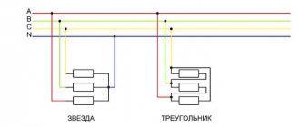
2 popular ways to connect a three-phase system:
- triangle;
- star.
Scheme “Triangle”
Each phase is connected to its neighbors. The current strength from the source is phase, between each other it is linear.
“Star” scheme
The phases are connected at one point. At this point, the total voltage will be 0. The current strength is only phase, and the voltage can vary from linear to phase. What does this give the user? Line voltage in the apartment is 380 V, and phase voltage is 220 V.
Most appliances operate at 220 V, but some appliances require more voltage: old electric stoves, powerful heaters and boilers, industrial power tools.
Thanks to this scheme, any device will work without problems.
How to find out your scheme
To correctly determine and calculate power, knowledge of several factors is required:
- Number of power phases;
- Method of connecting consumers.
For a single-phase connection, two wires are used:
- Phase wire;
- Neutral wire.
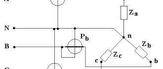
A three-phase network is characterized by the presence of three or four conductors (connection with a grounded neutral). In this case, two different switching schemes are used:
- "Triangle". Each load is connected to two adjacent ones. The voltage of each phase is supplied to the consumer connection points.
- "Star". All three consumers are connected at one point. The power phases are connected to the second ends. This is an isolated neutral circuit. In a circuit with a grounded neutral, the consumer connection point is connected to the neutral conductor.
Connecting source and consumers
Properties of a three-phase circuit
A three-phase network has a number of advantages:
- reduces losses when transporting electricity over long distances;
- cables and equipment have lower consumption than that of a monophase network;
- the energy system is balanced;
- In the system there are 2 forms of voltage for operation: linear 380 V and phase 220 V.
Three-phase or single-phase connection
Depending on what type of connection is used, the power consumption is determined differently.
In a single-phase network, the energy consumed is calculated using the simplest formula:
where cosϕ is the power factor characterizing the phase shift between current and voltage in a reactive load.
The power of a 3-phase network is the sum of consumption for each phase separately. The power formula for 3-phase current is as follows:
Ptotal=Uа∙Iа∙cosϕа+ Ub∙Ib∙cosϕb+ Uc∙Ic∙cosϕc,
where U, I, cosϕ are voltage, current and power factor in each phase, respectively.
For your information. It can be seen that in the general case, a three-phase connection requires a larger number of metering devices.
Sometimes you can calculate energy consumption using a simplified version. With symmetrical consumption, for example, when connecting an asynchronous motor, the consumption currents are the same, and the formula takes the following form:
Where:
- Uph, Iph – phase voltage and current;
- Ul, Il – linear voltage and current.
Three-phase circuits are a type of sinusoidal current circuits, and, therefore, all previously discussed methods of calculation and analysis in symbolic form fully apply to them. It is convenient to analyze three-phase systems using vector diagrams, which make it possible to quite simply determine phase shifts between variables. However, a certain specificity of multiphase circuits introduces characteristic features into their calculation, which, first of all, concerns the analysis of their operation in symmetrical modes.
Calculation of symmetrical operating modes of three-phase systems
A polyphase receiver and a polyphase circuit in general are called symmetrical,
if in them the complex resistances of the corresponding phases are the same, i.e.
If . Otherwise they are asymmetrical.
The equality of the modules of the indicated resistances is not a sufficient condition for the symmetry of the circuit. So, for example, the three-phase receiver in Fig. 1a is symmetrical, but in Fig. 1, b – no, even if: .
If a symmetrical three-phase generator voltage system is applied to a symmetrical three-phase circuit, then a symmetrical current system will take place in it. This mode of operation of a three-phase circuit is called symmetrical.
In this mode, the currents and voltages of the corresponding phases are equal in magnitude and are shifted in phase with respect to each other by an angle.
As a result of this, the calculation of such circuits is carried out for one - base
- phase, which is usually taken to be phase A. In this case, the corresponding values in other phases are obtained by formally adding a phase shift to the argument of the variable phase A while maintaining its modulus unchanged.
So for the symmetrical operating mode of the circuit in Fig. 2, and with known line voltage and phase resistances we can write
,
where is determined by the nature of the load.
Then based on the above
;
.
Complexes of linear currents can be found using the vector diagram in Fig. 2, b, from which it follows:
When analyzing complex circuits operating in symmetrical mode, calculations are carried out using two main techniques:
All triangles are replaced with equivalent stars. Since the triangles are symmetrical, then in accordance with the triangle-star transformation formulas.
Since all the original and newly obtained load stars are symmetrical, the potentials of their neutral points are the same. Therefore, without changing the operating mode of the circuit, they can be (mentally) connected by a neutral wire. After this, the base phase (usually phase A) is isolated from the circuit, for which a calculation is carried out, based on the results of which the corresponding values in other phases are determined.
Let, for example, for a given phase voltage it is necessary to determine the linear currents in the circuit in Fig. 3, all resistances in which are known.
In accordance with the specified methodology, we select the calculated phase A, which is presented in Fig. 4. Here , .
Then for the current we can write
,
and correspondingly .
Calculation of asymmetrical operating modes of three-phase systems
If at least one of the symmetry conditions is not met, an asymmetrical operating mode occurs in a three-phase circuit. Such modes, in the presence of only a static load in the circuit and neglecting the voltage drop in the generator, are calculated for the entire circuit as a whole by any of the previously discussed calculation methods. In this case, the phase voltages of the generator are replaced by corresponding sources of EMF. It can be noted that since in multiphase circuits, in addition to currents, node potentials are usually also of interest, the method of node potentials is most often used to calculate complex circuits. To analyze asymmetrical operating modes of three-phase circuits with electrical machines, the method of symmetrical components is mainly used, which will be discussed below.
For given line voltages, three-phase circuits are most easily calculated when connected in a triangle. Let in the diagram in Fig. 2,a. Then, for known complexes of linear voltages, in accordance with Ohm’s law
; ; .
Based on the found phase currents of the receiver, the linear currents are determined based on Kirchhoff’s first law:
.
Usually in practice, it is not the complexes of linear voltages that are known, but their modules. In this case, it is necessary to preliminarily determine the initial phases of these stresses, which can be done, for example, graphically. To do this, taking , based on the given voltage modules, we build a triangle (see Fig. 5), from which (by measuring) we determine the values of angles a and b.
Then
The required angles a and b can also be found analytically based on the cosine theorem:
When the generator and load phases are connected in a star and there is a neutral wire with zero resistance, the load phase voltages are equal to the corresponding voltages on the source phases. In this case, phase currents are easily determined by Ohm’s law, i.e. by dividing the known voltages on the consumer phases by the corresponding resistances. However, if the resistance of the neutral wire is high or there is no neutral wire, a more complex calculation is required.
Consider the three-phase circuit in Fig. 6, a. With a symmetrical supply and an asymmetrical load, in the general case it will correspond to a vector voltage diagram (see Fig. 6,b), in which the neutral points of the source and receiver occupy different positions, i.e. .
The potential difference between the neutral points of the generator and the load is called the neutral point bias voltage
(usually it is assumed that ) or simply
the neutral bias voltage.
The larger it is, the stronger the asymmetry of phase voltages at the load, which is clearly illustrated by the vector diagram in Fig. 6, b.
To calculate the currents in the circuit in Fig. 6,a it is necessary to know the neutral bias voltage. If it is known, then the voltages on the load phases are equal to:
.
Then for the desired currents we can write:
.
The relationship for the neutral bias voltage, written based on the nodal potential method, has the form
| . | (1) |
In the presence of a neutral wire with zero resistance, and from (1). If there is no neutral wire. With a symmetrical load, taking into account the fact that , it follows from (1) .
As an example of analyzing the asymmetrical operating mode of a circuit using relation (1), we determine which of the lamps in the circuit in Fig. 7 with direct phase rotation of the source will burn brighter if.
Let us write down the expressions for the complex resistances of the load phases:
Then for the neutral bias voltage we will have
Load phase voltages (hereinafter, the index N for source phase voltages is omitted)
Thus, the light bulb will burn brightest in phase C.
In conclusion, we note that if, when connecting to a star, linear voltages are specified (which is usually the case in practice), then taking into account the fact that the sum of the latter is zero, they can be uniquely specified using two sources of emf, for example, and . Then, since in this case , relation (1) is transformed into the formula
| . | (2) |
Literature
- Fundamentals
of circuit theory: Textbook. for universities / G.V. Zeveke, P.A. Ionkin, A.V. Netushil, S.V. Strakhov. –5th ed., revised. –M.: Energoatomizdat, 1989. -528 p. - Bessonov L.A.
Theoretical foundations of electrical engineering: Electric circuits. Textbook for students of electrical engineering, energy and instrument engineering specialties of universities. –7th ed., revised. and additional –M.: Higher. school, 1978. –528 p.
Test questions and tasks
- Which polyphase receiver is symmetrical?
- What mode of operation of a three-phase circuit is called symmetrical?
- What is the specificity of calculating symmetrical operating modes of three-phase circuits?
- Using what techniques is a three-phase symmetrical circuit reduced to a calculated single-phase one?
- What is neutral bias voltage and how is it determined?
- How can you determine complexes of linear voltages if their modules are given?
- What does a neutral wire provide with zero resistance?
- In the circuit in Fig. 6,a; ; ; . Line voltage is 380 V.
- In the diagram of the previous task; . The rest of the parameters are the same.
- In problem 8, the neutral wire is broken.
- In problem 9, the neutral wire is broken.
Determine the current in the neutral wire.
Answer: .
Determine the current in the neutral wire.
Answer: .
Determine the phase voltages at the load.
Answer: ; ; .
Determine the phase voltages at the load.
Answer: ; ; .
Characteristics of a three-phase system
A three-phase power supply system is characterized by several voltage and current values. It all depends on between which points of the circuit the measurements are made:
- between the phase wire and the neutral – phase voltage Uph;
- between individual phases – linear Ul.
The relationship between these parameters:
With symmetrical load distribution, the currents in all wires are equal. In a four-wire circuit (with a grounded zero), there is no current in the neutral conductor, so even if the zero is broken, the network continues to function normally.
In the case where the energy consumption differs between phases, some current flows in the neutral wire. A complete break in the neutral conductor causes a phase imbalance, so the voltage on the wires can change in the range from zero to linear.
The reactive nature of the load is taken into account by the power factor cosϕ. This value comes from the theory of complex numbers, which are used when it is necessary to calculate the parameters of alternating current circuits. In the case of an active load, cosϕ = 1, but the more reactive the consumers are, the more the coefficient decreases, showing how the real power decreases relative to the total.
Important! Therefore, to correctly calculate and reduce the load on generating equipment, power factor correctors are installed in reactive circuits. Circuits with a corrector bring the cosϕ coefficient closer to unity.
Three-phase circuit concept
So, a three-phase electrical circuit is a circuit in the branches of which there are three EMFs varying in time according to a harmonic law (sinusoidal law) with the same frequency, but having a phase shift relative to each other by an angle equal to 2π/3 (1200).
To obtain a three-phase harmonic signal, three-phase synchronous generators are used, in the three stator (armature) windings of which these EMFs are induced.
With the positive directions of the EMF indicated in the figure below (from the ends of the phases x, y, z to their beginnings a, b, c):
The emf will change according to the expressions below:
ea = Еam sin ωt,
Below are graphs of changes in these values over time:
When combining the EMF vector Ea with the axis of real values of the complex plane:
We obtain expressions for the EMF presented in complex form:
It should also be noted that the EMF Ea is usually directed upward vertically when constructing vector diagrams, which, in turn, corresponds to a rotation of the complex plane by 900 counterclockwise. In this case, the axes of imaginary and real quantities may not be indicated:
Using the positive direction and having information about the laws of change in EMF or having the corresponding graphs, you can determine the actual directions and instantaneous values of the EMF at any time. So, for example, at t = 0, ea = 0, a:
In the case when eb < 0 and ec > 0, then at t = 0 the emf ec and eb will be directed in different directions.
If you look at graph b), which shows a three-phase harmonic signal, you can see that phase A will reach its maximum value first, then phase B, and only then phase C. This sequence of phases reaching their maximum (amplitude) values is called a direct sequence of alternation phases If the rotor of a synchronous generator rotated in the opposite direction, then the phase sequence would be reverse C-B-A, and this would be a reverse phase sequence. The direction of rotation of both three-phase asynchronous electric machines and three-phase synchronous machines directly depends on this sequence. Calculations and analysis of three-phase circuits are usually carried out under the assumption that the system has direct phase rotation.
Calculation
Calculating the power of a three-phase system is difficult, because the current in the network is not constant, but alternating.
With constant current, power is calculated by multiplying voltage and current. With alternating current, all quantities are unstable due to the presence of several phases. The connection method also matters. With a single-phase system, power is also calculated by multiplying voltage and current, but taking into account the power factor-cos, which characterizes the phase shift between voltage and current for a reactive load.
The calculation takes place according to the following formula for the complete calculation of current power in a three-phase network:
Ptotal=Uа∙Iа∙cosа+ Ub∙Ib∙cosb+ Uc∙Ic∙cosc
where U is voltage, I is current, cos is power factor, a, b and c are phases.
Power measurement in three-phase circuits is carried out with a wattmeter.
With a symmetrical load, only one phase is measured and the measurement result is multiplied by 3. When measuring 3 phases at once, 3 devices will be required. In the absence of the “zero” phase, the measurement is carried out by 2 devices and the power calculation is calculated according to Kirchhoff’s 1st law:
Ia+Ib+Ic=0
The sum of the readings of two wattmeters will give an indicator of the power of the three-phase circuit.
Building a chart
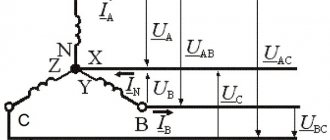
The vector diagram basically assumes the following values:
- Reference point N for all three separate phases.
- Vector direction of ABC as individual conductors of a voltage source (generator). Each vector has a given length equal to its voltage.
- The end of the vectors AB, BC, CA, as voltage receivers.
These values are supplemented by a unit of time during which the current, at a certain voltage and strength, reaches the receivers. Based on the construction, we get the result: UAB=UBC=UCA.
This means that if the phase voltage system is symmetrical, then the linear system is also symmetrical and equal, and in addition has a shift of 120 degrees. This is a simple definition of the vector of a three-phase circuit.
Alternating current is a sine wave that can be graphically superimposed on a coordinate axis. In this case, the vector has an angular rotation speed, which is equal to the angular frequencies of the current. When constructing, it is also necessary to take into account the fact that the vector is a graphical representation of the vibration amplitude, in which the vibration angle is equal to the initial reference point.
For example, the coordinate axis is set to 0. The offset angle is also known. Next, it is worth drawing the vector “Im”, which determines the direction of current movement. When constructing a vector using these values, the lead, lag, or phase shift parameters will become visible. This way you can visually see the difference in values on each conductor of the circuit.
How to calculate?
Ohm's law will help determine any quantity related to electrical energy. It states that voltage is equal to current times resistance, and power is force times voltage.
Current voltage is its strength multiplied by its resistance. The indicator is needed to select the optimal wires and cables in the house. It turns out that in order to calculate the current by power, you need to know its strength and voltage. But how to calculate amperes, knowing power and voltage, for example? Again following Ohm's law. To do this, you need to divide the power by the voltage.
To find the power, knowing the current and voltage, you need to multiply the force in amperes by the voltage in volts.
You can make an exact calculation using our calculator.
It is enough to simply find out the current strength; it is much more difficult to calculate the cross-section of the wires. To do this, you need to calculate the current strength and use the following table:
| Cross-section of copper wire depending on the amount of current consumed | ||||||||||||||
| Maximum current in amperes | 1 | 2 | 3 | 4 | 5 | 6 | 10 | 16 | 20 | 25 | 32 | 40 | 50 | 63 |
| Wire cross-section in millimeters | 0,17 | 0,33 | 0,52 | 0,67 | 0,84 | 1 | 1,7 | 2,7 | 3,3 | 4,2 | 5,3 | 6,7 | 8,4 | 10,5 |
In order to calculate the power, knowing the current and voltage, use the table below:
| Electrical equipment | Device power in watts | Power in amperes |
| Washing machine | 2000 | 10 |
| "Warm floor" | 1000 | 5 |
| Kitchen stove | 7000 | 35 |
| Microwave | 1000 | 5 |
| Dishwasher | 2000 | 10 |
| Fridge | 250 | 1 |
| Food processor | 1100 | 5 |
| Kettle | 1900 | 9 |
| Coffee maker | 1100 | 5 |
| Mixer | 300 | 1,4 |
| Hairdryer | 1000 | 2 |
| Iron | 1500 | 6 |
| Vacuum cleaner | 1200 | 5 |
| TV | 150 | 0,7 |
| Radio | 100 | 0,4 |
| Lamps | 50 | 0,2 |
Question Current in the neutral wire in three-phase circuits.
⇐ PreviousPage 2 of 4Next ⇒
Three-phase circuits with a neutral wire are called four-wire circuits.
Usually the resistance of the wires is not taken into account /
Then phase e.g. receiver will be equal to phase. generator voltage. .
Given that the complex resistances are equal, the currents are determined
In accordance with 1 order Kirgoff current in neutr. wire
When symmet. eg
When carrying eg
The neutral wire equalizes the phase voltages.
Operating modes of a three-phase successor.
There are two types of connections: star and triangle. In turn, when connected in a star, the system can be three- or four-wire.
Star connection
In Fig. Figure 6 shows a three-phase system when the generator and load phases are connected in a star. Here wires AA', BB' and CC' are linear wires.
Linear is the wire that connects the beginning of the phases of the generator and receiver windings. The point at which the ends of the phases are connected into a common node is called neutral (in Fig. 6 N and N' are the neutral points of the generator and load, respectively).
The wire connecting the neutral points of the generator and receiver is called neutral (shown with a dotted line in Fig. 6). A three-phase system when connected in a star without a neutral wire is called three-wire, with a neutral wire - four-wire.
All quantities related to phases are called phase variables, and those related to a line are called linear. As can be seen from the diagram in Fig. 6, when connected in a star, the linear currents and are equal to the corresponding phase currents. If there is a neutral wire, current flows in the neutral wire. If the system of phase currents is symmetrical, then. Consequently, if the symmetry of the currents were guaranteed, then the neutral wire would not be needed. As will be shown below, the neutral wire ensures the maintenance of symmetry of voltages across the load when the load itself is unbalanced.
Since the voltage at the source is opposite to the direction of its EMF, the phase voltages of the generator (see Fig. 6) act from points A, B and C to the neutral point N; — phase load voltages.
Line voltages act between line wires. In accordance with Kirchhoff's second law for linear voltages, we can write
| ; | (1) |
Note that it is always the sum of voltages along a closed loop.
In Fig. Figure 7 shows a vector diagram for a symmetrical voltage system. As its analysis shows (the rays of phase voltages form the sides of isosceles triangles with angles at the base equal to 300), in this case
| (4) |
Usually in calculations it is taken. Then for the case of direct phase alternation , (with reverse phase alternation, the phase shifts y and change places). Taking this into account, based on relations (1) ... (3), complexes of linear voltages can be determined. However, with voltage symmetry, these quantities are easily determined directly from the vector diagram in Fig. 7. Directing the real axis of the coordinate system along the vector (its initial phase is zero), we count the phase shifts of linear voltages with respect to this axis, and determine their modules in accordance with (4). So for linear voltages we get: ; .
Triangle connection
Due to the fact that a significant part of the receivers included in three-phase circuits are asymmetrical, it is very important in practice, for example, in circuits with lighting devices, to ensure the independence of the operating modes of individual phases. In addition to the four-wire circuit, three-wire circuits also have similar properties when the receiver phases are connected in a triangle. But the generator phases can also be connected into a triangle (see Fig. 8).
For a symmetric EMF system we have
.
Thus, in the absence of load in the generator phases in the circuit in Fig. 8 currents will be zero. However, if you swap the beginning and end of any of the phases, then a short circuit current will flow in the triangle. Therefore, for a triangle, the order of connecting the phases must be strictly observed: the beginning of one phase is connected to the end of another.
The diagram for connecting the phases of the generator and receiver into a triangle is shown in Fig. 9.
It is obvious that when connected in a triangle, the line voltages are equal to the corresponding phase voltages. According to Kirchhoff's first law, the connection between the linear and phase currents of the receiver is determined by the relations
Similarly, line currents can be expressed through the phase currents of the generator.
In Fig. Figure 10 shows a vector diagram of a symmetrical system of linear and phase currents. Its analysis shows that with current symmetry
| . | (5) |
In conclusion, we note that in addition to the considered star-star and delta-delta connections, star-delta and delta-star circuits are also used in practice.
⇐ Previous2Next ⇒
Recommended pages:
Measuring power with a wattmeter
The power consumption of three-phase current is measured using wattmeters. This can be a special wattmeter for a 3-phase network, or a single-phase one connected according to a specific circuit. Modern electricity metering devices are often made using digital circuitry. Such designs are characterized by high measurement accuracy and greater capabilities for operating with input and output data.
Measurement options:
- Star connection with neutral conductor and symmetrical load - the measuring device is connected to one of the lines, the readings taken are multiplied by three.
- Asymmetrical current consumption in a star connection - three wattmeters in the circuit of each phase. The wattmeter readings are summed up;
- Any load and delta connection - two wattmeters connected in a circuit of any two loads. The wattmeter readings are also summed up.
In practice, they always try to make the load symmetrical. This, firstly, improves network parameters, and secondly, simplifies the accounting of electrical energy.
Three-phase load connected in star connection
If the loads (receivers) are connected in a three-phase circuit according to the “star” circuit (Fig. 1), then phase voltages are applied to the load resistances. Linear currents are equal to phase currents and are determined by Ohm’s law:
and the current in the neutral is equal to the vector sum of these currents: I N
=
I A
+
I B
+
I C
.
Fig.1
At symmetrical voltages UA
,
UB
,
UC
and the same resistances
RA
=
RB
=
RC
=
R
the currents
IA
,
IB
,
IC
are also symmetrical and their vector sum (
IN
) is zero. Then
IL =
IФ
=
UФ ¤ R
;
IN
= 0.
If the load phase resistances are not the same, then some current IN
No. 0. This is illustrated in vector diagrams (Fig. 2).
Fig.2.
The power of a three-phase load is the sum of the phase powers: S P =
PA + PV + PC.
When the load is symmetrical and purely resistive, we have
S P = 3
PF
=
3 UФ × IФ
.
With a mixed (active-inductive or active-capacitive) load:
Active power
S P = 3
× UФ × IФ × cos j = Ö3 × UL × IL × cos j
.
Reactive power
S Q = 3
× UФ × IФ × sin j
=
Ö3 × UL × IL × sin j
.
Full power
S S = 3
× UФ IФ = Ö3 × UЛ × IЛ
.
Formulas for DC circuit calculations
The easiest way to calculate the power is for a DC circuit. If there is current and voltage, then you just need to perform the calculation using the formula given above:
P=UI
But it is not always possible to find power by current and voltage. If you don't know them, you can determine P by knowing the resistance and voltage:
P=U2/R
You can also perform the calculation knowing the current and resistance:
P=I 2 *R
The last two formulas are convenient for calculating the power of a section of a circuit if you know the R of the element I or U that falls on it.
Equipment for network short circuit protection
You already know how to calculate amps when you know the power and voltage, or calculate power when you know the current and voltage. But sometimes even accurate and correct calculations do not save you from a short circuit. An emergency can happen on a three-phase line for reasons beyond the control of the user: a foreign object hitting the wires, a break due to a falling tree. In this case, even if you have calculated the current strength as correctly as possible and your house has the most ideal wiring, a fire or failure of electrical appliances is possible. You can protect your network in the following ways:
- install a fuse. If the amperes in the electrical circuit exceed the permissible values, the fuse will melt and the circuit will be broken. The price of a fuse is 400-600 rubles. Choose a domestically produced product designed to work with our electrical networks;
- install a circuit breaker. This is modern equipment that reliably protects household appliances from premature failure due to problems with wires. Costs from 200 to 2 thousand rubles. It will blow in seconds, unlike a fuse, which will take about half a minute to open. When connecting, study detailed information about wire markings.
An automatic current switch will protect household appliances from damage due to a short circuit.
Advantages of three-phase systems
Unlike single-phase, three-phase systems have a number of advantages, namely:
- It is the three-phase system that makes it possible to obtain a rotating magnetic field, which allows the use of three-phase asynchronous electric motors;
- Improves the technical and economic performance of transformers and generators;
- Simplifies the system for generating and transmitting electrical energy from the generator to the consumer;
- Allows you to connect to the network electrical receivers designed for different voltage ratings (linear and phase);
Three-phase systems are most widespread. Electrical energy generated at power plants is delivered and distributed among consumers in the form of three-phase alternating current energy.
Example of calculating total power for an electric motor
The power of electric motors can be useful or mechanical on the shaft and electrical. They differ by the coefficient of performance (efficiency), this information is usually indicated on the nameplate of the electric motor.
From here we take the data to calculate the connection in a triangle to Ulinear 380 Volts:
Then you can find the active electrical power using the formula:
P=Pon the shaft/n=160000/0.94=170213 W
Now we can find S:
It is this that needs to be found and taken into account when selecting a cable or transformer for an electric motor. This completes the calculations.
Selecting the rating of the circuit breaker
Applying the formula I = P/209, we find that with a load with a power of 1 kW, the current in a single-phase network will be 4.78 A. The voltage in our networks is not always exactly 220 V, so it would not be a big mistake to calculate the current strength with a small margin like 5 A for every kilowatt of load. It is immediately clear that it is not recommended to connect an iron with a power of 1.5 kW to an extension cord marked “5 A”, since the current will be one and a half times higher than the rated value. You can also immediately “graduate” the standard ratings of the machines and determine what load they are designed for:
- 6 A – 1.2 kW;
- 8 A – 1.6 kW;
- 10 A – 2 kW;
- 16 A – 3.2 kW;
- 20 A – 4 kW;
- 25 A – 5 kW;
- 32 A – 6.4 kW;
- 40 A – 8 kW;
- 50 A – 10 kW;
- 63 A – 12.6 kW;
- 80 A – 16 kW;
- 100 A – 20 kW.
Using the “5 amperes per kilowatt” technique, you can estimate the current strength that appears in the network when connecting household devices. You are interested in peak loads on the network, so for the calculation you should use the maximum power consumption, not the average. This information is contained in the product documentation. It is hardly worth calculating this indicator yourself by summing up the rated powers of the compressors, electric motors and heating elements included in the device, since there is also such an indicator as the efficiency factor, which will have to be assessed speculatively with the risk of making a big mistake.
When designing electrical wiring in an apartment or country house, the composition and passport data of the electrical equipment that will be connected are not always known for certain, but you can use the approximate data of electrical appliances common in our everyday life:
- electric sauna (12 kW) - 60 A;
- electric stove (10 kW) - 50 A;
- hob (8 kW) - 40 A;
- instantaneous electric water heater (6 kW) - 30 A;
- dishwasher (2.5 kW) - 12.5 A;
- washing machine (2.5 kW) - 12.5 A;
- Jacuzzi (2.5 kW) - 12.5 A;
- air conditioner (2.4 kW) - 12 A;
- Microwave oven (2.2 kW) - 11 A;
- storage electric water heater (2 kW) - 10 A;
- electric kettle (1.8 kW) - 9 A;
- iron (1.6 kW) - 8 A;
- solarium (1.5 kW) - 7.5 A;
- vacuum cleaner (1.4 kW) - 7 A;
- meat grinder (1.1 kW) - 5.5 A;
- toaster (1 kW) - 5 A;
- coffee maker (1 kW) - 5 A;
- hair dryer (1 kW) - 5 A;
- desktop computer (0.5 kW) - 2.5 A;
- refrigerator (0.4 kW) - 2 A.
The power consumption of lighting devices and consumer electronics is small; in general, the total power of lighting devices can be estimated at 1.5 kW and a 10 A circuit breaker is sufficient for a lighting group. Consumer electronics are connected to the same outlets as irons; it is not practical to reserve additional power for them.
If you sum up all these currents, the figure turns out to be impressive. In practice, the possibility of connecting the load is limited by the amount of allocated electrical power; for apartments with an electric stove in modern houses it is 10 -12 kW and at the apartment input there is a machine with a nominal value of 50 A. And these 12 kW must be distributed, taking into account the fact that the most powerful consumers concentrated in the kitchen and bathroom. Wiring will cause less cause for concern if it is divided into a sufficient number of groups, each with its own machine.
For the electric stove (hob), a separate input with a 40 A automatic circuit breaker is made and a power outlet with a rated current of 40 A is installed; nothing else needs to be connected there. A separate group is made for the washing machine and other bathroom equipment, with a machine of the appropriate rating. This group is usually protected by an RCD with a rated current 15% greater than the rating of the circuit breaker. Separate groups are allocated for lighting and for wall sockets in each room.
You will have to spend some time calculating powers and currents, but you can be sure that the work will not be in vain. Well-designed and high-quality electrical wiring is the key to the comfort and safety of your home.
Calculation of Power by Current and Voltage
To protect yourself when working with household electrical appliances, you must first correctly calculate the cross-section of the cable and wiring. Because if the cable is chosen incorrectly, it can lead to a short circuit, which can lead to a fire in the building, the consequences can be catastrophic.
This rule also applies to the choice of cable for electric motors.
Calculation of power by current and voltage
This calculation occurs based on the actual power; it must be done before you start designing your home (house, apartment).
- This value determines the cables that power the devices that are connected to the electrical network.
- Using the formula, you can calculate the current strength; for this you need to take the exact network voltage and the load of the powered devices. Its size gives us an idea of the cross-sectional area of the veins.
If you know all the electrical appliances that should be powered from the network in the future, then you can easily make calculations for the power supply diagram. The same calculations can be performed for production purposes.
Single-phase 220 volt network
Current formula I (A - amperes):
Where P is the electrical full load (its designation must be indicated in the technical data sheet of this device), W - watt;
U—mains voltage, V (volts).
The table shows the standard loads of electrical appliances and the current they consume (220 V).
| electrical appliance | Power consumption, W | Current strength, A |
| Washing machine | 2000 – 2500 | 9,0 – 11,4 |
| Jacuzzi | 2000 – 2500 | 9,0 – 11,4 |
| Electric floor heating | 800 – 1400 | 3,6 – 6,4 |
| Stationary electric stove | 4500 – 8500 | 20,5 – 38,6 |
| microwave | 900 – 1300 | 4,1 – 5,9 |
| Dishwasher | 2000 — 2500 | 9,0 – 11,4 |
| Freezers, refrigerators | 140 — 300 | 0,6 – 1,4 |
| Electric meat grinder | 1100 — 1200 | 5,0 — 5,5 |
| Electric kettle | 1850 – 2000 | 8,4 – 9,0 |
| Electric coffee maker | 6з0 — 1200 | 3,0 – 5,5 |
| Juicer | 240 — 360 | 1,1 – 1,6 |
| Toaster | 640 — 1100 | 2,9 — 5,0 |
| Mixer | 250 — 400 | 1,1 – 1,8 |
| Hairdryer | 400 — 1600 | 1,8 – 7,3 |
| Iron | 900 — 1700 | 4,1 – 7,7 |
| Vacuum cleaner | 680 — 1400 | 3,1 – 6,4 |
| Fan | 250 — 400 | 1,0 – 1,8 |
| TV | 125 — 180 | 0,6 – 0,8 |
| Radio equipment | 70 — 100 | 0,3 – 0,5 |
| Lighting devices | 20 — 100 | 0,1 – 0,4 |
In the figure you can see a diagram of the power supply device at home with a single-phase connection to a 220 volt network.
Device diagram for single-phase voltage
As shown in the figure, all consumers must be connected to the appropriate machines and meter, then to a general machine that will withstand the total load of the house. The cable that will carry the current must withstand the load of all connected household appliances.
The table below shows hidden wiring for a single-phase housing connection to select a cable at a voltage of 220 volts.
| Wire core cross-section, mm 2 | Conductor core diameter, mm | Copper conductors | Aluminum conductors | ||
| Current, A | Power, W | Current, A | power, kWt | ||
| 0,50 | 0,80 | 6 | 1300 | ||
| 0,75 | 0,98 | 10 | 2200 | ||
| 1,00 | 1,13 | 14 | 3100 | ||
| 1,50 | 1,38 | 15 | 3300 | 10 | 2200 |
| 2,00 | 1,60 | 19 | 4200 | 14 | 3100 |
| 2,50 | 1,78 | 21 | 4600 | 16 | 3500 |
| 4,00 | 2,26 | 27 | 5900 | 21 | 4600 |
| 6,00 | 2,76 | 34 | 7500 | 26 | 5700 |
| 10,00 | 3,57 | 50 | 11000 | 38 | 8400 |
| 16,00 | 4,51 | 80 | 17600 | 55 | 12100 |
| 25,00 | 5,64 | 100 | 22000 | 65 | 14300 |
As shown in the table, the cross-section of the cores also depends on the material from which it is made.
Calculation formulas and examples
For the most accurate calculations, the reactive load is always taken into account. All inductive devices have it. That is, those that use a winding in their design. These are electric motors, transformers, chokes. Also, reactive power depends on the capacitive load that the capacitors have.
Before making calculations, you just need to remember:
- The resistor takes on only active power. It is subsequently released in the form of light or heat.
- The inductor provokes a reactive reaction, which is expressed in the form of a magnetic field.
- The capacitor produces reactance.
The power of a three-phase network can be calculated using the formula:
P = (U1 × I1 × cosϕ1) + (U2 × I2 × cosϕ2) + (U3 × I3× cosϕ3)
Types of connection to a three-phase network and basic formulas for calculations Source rusenergetics.ru
U and I are voltage and current. The numbers indicate the serial number of the phase (we have three). And cosϕ is the power factor, which is found by multiplying the active and reactive load by each other. The first quantity is usually considered constant – 1.
In most cases, the reactive load on the network is very small. Therefore, the coefficient is assigned a value of 0.95. This is the work of an electric stove, heater, incandescent light bulbs, and electric kettle. But if you connect a welding machine or a pump with a powerful motor to the network, the reactive load will already differ significantly. And for simplicity of calculations, when using such units, the coefficient is assigned a value of 0.8.
If we consider each phase as a separate linear load, then we can significantly reduce the calculation of the power of a three-phase network. After all, we can assume that each phase carries a voltage of 220 volts. And the current strength is the same for all lines.
Therefore, the formula for three-phase current power is simplified:
P = 3 × 220 × I × cosϕ
To find out the current strength, you need to find the value of the resistance (R) of the network. And then you can use the formula: I = U / R. The voltage (U) is taken linear - 220 volts.
Digital wattmeter for three-phase network Source asset.conrad.com