- December 6, 2020
- Electricity
- Yulia Tolok
Every owner should know how to calculate electricity (calculate its consumption, in other words). In this case, electricity consumption refers to the amount of electrical energy that devices use to operate. You need to know its consumption in order to assess your purchasing power, avoid making mistakes when paying, and also evaluate what measures can be taken to improve energy efficiency and where you can save.
The total consumption of all devices that are connected to the network can be calculated using an individual meter. He will also answer the question of how to calculate the payment for electricity. A slightly more complicated situation is to calculate the consumption of an individual device.
Characteristics of electric current
The device passport may indicate various characteristics indicating its consumption, but most often these are supply voltage, current or power (usually at maximum load). Often the voltage is omitted, since it means that all goods produced on the territory of the Russian Federation or imported here are designed for a voltage of 220 V. In the USA, this parameter is 110-120 V.
From school physics courses, many remember that current is measured in amperes, voltage in volts, and power in watts. It is necessary to note that for more powerful devices the latter can be indicated in kilowatts, which are proportional to one thousand watts.
Sometimes the device's passport indicates electricity consumption, not power. It is important to pay attention to the period for which it is indicated; it could be a year, a month, a day, and so on. Electricity is paid in kW-hours, which is indicated as kWh. There is a common notation kW/hour or “kilowatt per hour”, which is incorrect when it comes to electricity consumed. In fact, these units measure the speed of construction of power plants. Sometimes a multiple of it, mW/year, is also found.
Theory. Active and reactive power
Reactive power is consumed by electric motors, inductors, and transformers that are used in household electrical appliances; it is not spent on conversion into mechanical or thermal energy in their windings, but is spent on eddy currents and magnetization reversal in the cores.
If you take a single-phase electric motor, then its passport data will indicate: active power, current consumption, network voltage, power factor or cosine phi (cosφ), efficiency, etc., but nothing about reactive power. To calculate reactive power consumption, you need to know the power factor. For example, we know the power of a single-phase electric motor of 980 W, rated voltage 220 V and power factor cosφ = 0.85. Using formulas from the electrical engineering course, we determine the rated current:
I=(P/U)*cosφ=(980/220)*0.85=5.24 A.
We calculate reactive power:
The reactive current will be equal to:
IL=I*sinφ=5.24*0.526=2.76 A.
Then the total will be equal to:
S=U*I=220*5.24=1152.8 V*A.
In addition, an electronic electricity meter does not have moving parts in its structure, so it begins to take readings at a very small consumed load current (at 0.25 mA), and also has a smaller measurement error compared to an induction one.
Based on this, it is recommended to disconnect from the power supply all electrical consumers that are in “standby” mode, because This is an additional overpayment for electricity.
The induction meter “does not respond” to a low-power inductive load, as well as when this load operates in no-load mode, that is, the low side of the power transformer is not loaded.
In addition, the disk of this meter begins to slowly rotate in the opposite direction when one of the ends of the inductor is connected. This is possible when using a lamp of the LB-2*40 brand with a choke, when it is not the phase wire that is interrupted through the switch, but the neutral wire.
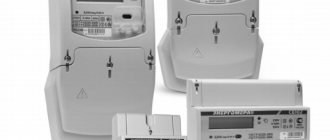
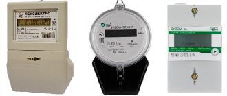
Electricity meter
Electric meters today are found in almost every apartment or house. They help you pay exactly how much electricity is consumed and, if necessary, save it.
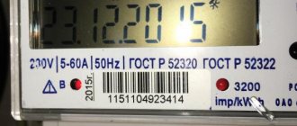
Previously, all electricity meters were mechanical. Their display looked like rotating drums with numbers that showed the amount of electricity consumed. Now this is a digital display with many additional functions, such as dividing consumption into tariff zones, calculating average consumption, indicating the presence of current in the network, and so on.
Using a meter, you can calculate the electricity consumption of a specific device. To do this, you need to turn off all other equipment in the house and leave only the one that interests you. Record the time, for example an hour. And see how many kW*hours the meter will “wind up”. If you calculate the time over a shorter period of time, then you should multiply these meter readings by the desired coefficient.
It should be noted that most devices consume less than 1 kWh. In this case, you should pay attention to the last digit, which is highlighted in red or after the decimal point. These are tenths. If you take them into account, the indicator will be more accurate.
Not all equipment constantly consumes the amount of electricity indicated in the passport. Depending on the operating mode, this number is usually lower. The refrigerator freezes only when the temperature rises above a predetermined interval, and the washing machine consumes more if the heating elements or pump are turned on, but is practically idle when the laundry is soaking. Energy consumption is calculated based on the power of each device and their total.
Five reasons for over-metering of electricity consumption by new electronic electricity meters
In the article, the author describes situations when, after installing new electronic electricity meters, they will count, in the same apartments, more electricity consumption than the old induction ones. Explains the reasons for over-metering, provides diagrams and gives recommendations for eliminating shortcomings and saving energy.
Electricity consumer complaint: “I live in water from apartments in an apartment building. Previously, to account for electricity consumption in my apartment, a CO-2 induction electric meter was installed in the power panel on the staircase; it counted for many years, in winter more in summer, less, but there was no more than 100 kW/hour per month. Now “Kievenergo” has replaced it and installed an electronic electricity meter NIK 2102 and it totals 2 times more, and this despite the fact that the load in my apartment has not changed.”
There are a lot of similar complaints on the Internet. Let's look at the reasons for over-metering of electricity by electronic meters.
New electronic-mechanical meters
Old induction electricity meters of the CO-2 type, installed en masse and for a long time in our apartments, counted active power, many hearths worked reliably, but had a number of disadvantages. Among them, low sensitivity, they only took into account powers above 11...22 W (depending on the accuracy class), further, they could easily be deceived, i.e. stop electricity metering, which is what the “craftsmen” did en masse. All egos led to losses for energy supply organizations, which have now become private, and the private owner will not tolerate losses. Therefore, on the instructions of energy supply organizations, designers have developed new, electronic (electromechanical) electricity meters (ES) that are devoid of the above disadvantages. The market is oversaturated with such ES, among them the electronic-mechanical electric meter type NIK 2102 (Fig. 1), which is produced in Ukraine and has many modifications, which is often mentioned on the Internet. It fully complies with the requirements of energy sales, namely, it considers active power and has high sensitivity, because takes into account power consumption above 2.75 W (and not 11...22 W as in CO-2). It contains many methods of protection against electricity theft. Among them, high immunity to artificial external magnetic fields and external radio emissions, and also, depending on the model, one current sensor can be installed (only in the phase wire), or two current sensors (in the phase and neutral wire).
You can find out how many current sensors your NIK 2102 electric meter has by three criteria.
- The first sign, according to the type of model written on its front panel, for example, in the model НІК 2102-02.М2В the number after the letter “M” indicates the number of current sensors, in this case “2”.
- The second sign is the presence on the same panel of an LED with the inscription “EARTH” and “REVERSE” (Fig. 1); electric meters with one current sensor do not have these LEDs. By the way, the “REVERSE” LED lights up when “craftsmen” send current in the opposite direction in order to steal electricity.
Rice. 1
- The third sign is that on the front panel of the ES there is a sign indicating how many current sensors are in this model; the sign is a vertical stick with one or two rings at its ends. One ring - one current sensor, two rings - two current sensors.
Energosbyt really likes the ES NIK 2102 with 2 current sensors and installs them en masse and free of charge in power metal panels in all our apartment buildings.
Where does energy sales come from so much love for new electric meters with 2 current sensors? And the whole trick is that the ES takes into account the energy consumption according to the readings of the sensor (phase or zero) through which the greater current flows. On the one hand, this makes it difficult to steal electricity, but on the other hand, it allows energy sales electricians to incorrectly connect ES and thereby deceive consumers, i.e. charge them a bill for electricity that they do not actually consume.
Areas of responsibility
Before understanding all the reasons for over-metering of electricity, it is necessary to know the areas of responsibility of the power grid sections, i.e. who is responsible for what.
The housing office or the electrician of the joint owners of the apartment building is responsible for the power switchboard of an apartment building (on the staircase).
Energosbyt is responsible for the electrical system in the electrical panel of an apartment building and its connection wires (to the circuit breakers AB), as well as the sealing and operation of the electrical system.
The owner of the apartment is responsible for the electrical wiring of an apartment or apartment building, starting from the circuit breakers (AB) in the power panel.
In a private house, everything belongs to the owner of the house: the power panel, the electric meter, the house's electrical wiring and grounding (if any), but the seals on the electric meter belong to the energy sales company, and they cannot be torn off after sealing.
So, let's consider 5 reasons for the overestimation of ES of the new generation of electricity.
- Energy sales electrician, replaced an old electrical system in the electrical panel of an apartment building with an electronic one with two current sensors
But he connected it according to the wrong circuit, which is why the ES produces much more electricity than the apartment owner consumes. This is one of the most common reasons for overbilling electricity.
Looking through the Internet, I was surprised that no one even knows about this scam by energy sales electricians, but it is used all the time.
In Fig. Figure 2 shows two wiring diagrams for connecting the ES in the power panels of our apartment buildings; in Fig. 2, a there is a diagram of the correct connection of the ES, and in Fig. 2, b there is a diagram of the incorrect one.
Rice. 2
It is correctly turned on - this means that the output of the neutral wire from the electrical system to the apartment should be direct (Fig. 2, a), and not in a gap, through the electrical panel housing (Fig. 2, b). When turned on correctly (Fig. 2, a), the same current flows in both wires of the ES (phase and zero), and the ES correctly charges electricity.
But often, the electrician, either due to his incompetence, or on purpose, connects the electrical system to the apartment incorrectly (Fig. 2, b). Those. The output of the neutral wire from the ES and its entrance to the apartment are connected not directly, but through the metal housing of the power electrical panel, and even under one clamp bolt with neighbors (Fig. 2, b). Then, additional current circulating in the metal body of the electrical panel will be mixed into the neutral wire from the neighbors in the electrical panel, and the ES will charge you with additional electricity that you do not consume.
The circulation diagram of the neutral wire currents in the metal casing of the electrical panel changes all the time, because depends on the ratio of current consumption of all neighbors’ apartments in the electrical panel. Usually there are 3-4 electrical switchboards in electrical panels, but in Fig. 2, for simplicity, only two are shown.
Moreover, neighbors can influence your ES in the same way as you influence it, naturally, if they are also turned on according to the wrong scheme (Fig. 2, b).
To be fair, it should be noted that the designers of an ES with two current sensors, the same NIK 2102, provided an “EARTH” LED on its front panel (Fig. 1). Its glow indicates that different currents are passing through the phase and neutral wires; this is not a normal condition and you are charged additional electricity that you do not consume.
It is very easy to identify the reason for the glow of the EARTH LED; there are two options.
- First. Check the circuit, i.e. wires, ES connections. The neutral wire from the ES must be connected directly to the apartment (Fig. 2, a), and not through the electrical panel housing (Fig. 2, b).
- Second. In the power panel, turn off the power supply to your apartment (turn off the AB automatic switches), the “EARTH” LED on your ES will go out. After which, the load must be replaced with a portable incandescent lamp 230 V 100 W, i.e. turn it on as shown in Fig. 3. If the “EARTH” LED lights up, this indicates that the electric meter is not turned on correctly, and the electrician who did this is to blame.
Rice. 3
In new apartment buildings, with new electrical wiring, the above-described problems with ES, as a rule, do not occur, but in old Soviet-built buildings, they are all too common.
How to act in a situation when you discover that on your electricity meter, in the power panel of an apartment building, the “EARTH” LED is glowing. There are three options.
- First. Write an application addressed to the director of the energy sales (RES) of your area, in which, in addition to your address and your data, you indicate that the “EARTH” LED is lit on the ES of your apartment and that the electrical wiring of your apartment is working properly, and that the electrician of the energy sales will eliminate this deficiency. The application must be written in 2 copies, one must be left in the director’s reception area, and the second, with the “incoming” stamp, must be kept at home.
- Second. At the appointed time, you can come to see the director, but you must write an application, because oral conversation is empty talk, and no one will come to you.
- Third. Call the power supply electricians, pointing out the above-mentioned deficiency. This is the simplest option, but also the most unpromising, because... there is almost no chance that an electrician will come to you; they will simply “football” you, as was the case with the author of this article.
If the electrician of the energy sales, on the instructions of the director, nevertheless comes to you to eliminate the deficiency, then he will definitely lie to you that your neighbor, who connected to your meter, is to blame. You will hate your neighbor, consider him your enemy and even quarrel with him, but he is absolutely innocent and does not even know about it. But in fact, all the blame lies with the energy sales electrician, but he will never admit it [1]. But your task, when it appears, is to eliminate the deficiency.
- Poor insulation of electrical wiring in your apartment or private house (dacha)
As a result, the electric meter contains additional electricity, even in the absence of a payload. This is another reason for the increased metering of electricity by the electric meter, but the energy supply company is not to blame, because The electrical wiring of an apartment (private house) belongs to its owner.
Poor insulation in electrical wiring, both between wires and “to the ground,” may be due to its old age, or moisture (water) getting into the electrical wiring, for example, your neighbors flooded you. The same situation can happen in a cable that you laid in the ground to a garage, or a summer kitchen, or a bathhouse on the territory of a summer house or private house, and groundwater, the worst enemy of insulation, got into this cable.
According to the standards of the “Rules for Accounting for Electrical Installations” (RUE), the insulation resistance of electrical wiring must be at least 0.5 MOhm. But ES begin to take into account electricity from current leakage, at much lower insulation resistance values. For example, old ES type SO-2 take into account powers above 11...22 W, which corresponds to an insulation resistance below 4.4...2.2 kOhm. New, electronic ES have a higher sensitivity; they take into account electricity with a power above 2.75 W, i.e. if the insulation resistance is less than 17.6 kOhm. When the insulation resistance of the electrical wiring is below the above threshold, the ES generate electricity “day and night”, regardless of whether you consume electricity or not.
A specialist knowledgeable in electrical engineering should identify low insulation in electrical wiring. As you know, an electronic-mechanical ES, the same NIK 2102, when counting electricity, blinks an LED. By disconnecting sections of electrical wiring one by one, the specialist identifies electrical wires with reduced insulation, measures the insulation resistance with a device, and makes a conclusion about the need to replace the wiring. Faulty, i.e. The culprits of current leakage may also be automatic circuit breakers AB (Fig. 2, a) installed in power panels, although this happens rarely, but a specialist should check them too. Based on the results of the examination, the specialist makes a conclusion.
If you, without inspecting the apartment electrical wiring, complain to the electricians of the energy sales about the large electricity metering of the new ES, then they, in order not to deal with the essence of the problem, will answer you in the standard way: “Change the electrical wiring, the energy sales is not responsible for the electrical wiring of your apartment.” The owner of the apartment, having received such a “competent conclusion” without an inspection, spends a lot of money, changes the wiring, and the ES, as he counted 2 times more, still counts, because the reason may be completely different.
- The owner of a private house incorrectly connected the grounding in the power panel
This is another reason for over-metering of electricity.
I’ll start with a complaint from the owner of the dacha: “At my dacha I have an electromechanical meter NIK 2102 with two current sensors; I equipped the dacha with grounding and connected it in the power panel to the neutral wire bus. An electrician neighbor advised us to protect ourselves from lightning or an emergency situation when the neutral wire on the poles breaks. Imagine my surprise when, after a month, the amount of electricity I consumed almost doubled, and I don’t understand why.”
Figure 4a shows a diagram of such a grounding connection to the neutral bus in the power panel. It is impossible to connect the grounding to the neutral wire after the ES, anywhere, neither in the electrical panel, nor in a three-pin socket in an apartment or house. Because an additional (equalizing) current will flow through the current sensor of the ES neutral wire (in Fig. 4a it is shown by a dotted line with an arrow). And the ES will account for additional electricity that the owner of a private house does not consume. The amount of accrued electricity can be significant and depends on the magnitude of the equalizing current. It can be easily measured with a current clamp - to do this, you need to wrap it around the ground wire.
Rice. 4
Equalizing currents of different sizes flow through all groundings of the neutral (PEN) wire, along the entire path from the supply transformer to the consumer (Fig. 5), including the grounding of power boards of private houses (Fig. 4, a, Fig. 4, b).
The existence of equalizing currents is due to the fact that on the supply three-phase transformer (10 kV / 380 V) the three phase windings (400 V) are connected by a star and their common neutral wire is grounded.
This 4-wire consumer power supply system is called TN-C (Fig. 5). The magnitude of the equalizing currents, the greater, the lower the grounding resistance and the greater the power currently consumed by all consumers connected to the supply transformer, for example 10 kV / 0.4 kV (Fig. 5). True, if the currents in each of the three phases of the network are equal, the current in the neutral wire will be practically zero, but there is no exact equality of currents in all phases.
Rice. 5
But, in the event of emergency situations, for example, when the neutral wire on the poles breaks, this current can reach significant values, tens of amperes or more, and if the connections to the ground in the electrical panel are made according to the diagram in Fig. 4, a, i.e. after ES, then it will count a lot of electricity that the consumer did not actually consume.
What is the right thing to do in this situation? Here are three options.
- First. Do not connect the ground to the neutral bus of the power panel and there will be no problems, but use the equipped ground only as the third wire in sockets, as a protective ground. The magnitude of the current in the protective grounding, with proper insulation of electrical appliances, is always zero, this can be verified with a current clamp.
- Second. If you decide to follow the recommendation of your electrician neighbor, or you were forced to do so by the power supply, then connect the grounding to the ES, according to the diagram in Fig. 4, b. With such a scheme, the additional (equalizing) current, although it will flow in the grounded neutral wire, will go past the ES, because grounding is connected before it.
- Third option. In a private house, install an ES with only one current sensor (in the phase wire); such a model is also available - NIK 2102. It will charge electricity only through the phase wire.
The disadvantage of the circuit shown in Fig. 4, b is the absence of a limiter for extremely large equalizing currents that arise in emergency situations and can burn the connecting cable of the house owners to the power pole, as well as the electric meter and power panel. Therefore, practicing electricians recommend connecting the ground to the neutral wire according to the diagram in Fig. 6. In it, as in Fig. 4, b, an electric meter with two current sensors is installed, but in front of the ES a paired automatic switch AB-2 is added, for example, for a current of 32 A, which in emergency situations (large equalizing currents) will automatically turn off and phase and zero and this will protect the connecting electrical cable and ES from damage.
Rice. 6
When using the diagram in Fig. 6, the power sales department seals the paired AV-2 automatic machine using a special sealing box, and when using the diagram in Fig. 4, b, they seal the junction of the grounding to the housing and the branch to the ES, everything is done to prevent deliberate shutdown of the ES, for the purpose of stealing electricity. The diagrams shown in Fig. 4, b, Fig. 6 are shown as simplified options for connections in the electrical panel; for example, they do not show differential circuit breakers, which are recommended to be installed in power panels. The main purpose of these diagrams is to show how to avoid charging ES electricity from equalizing currents.
- All household appliances of the apartment (house): televisions, computers, laptops, microwave ovens, DVD players, stereo systems, etc., are constantly connected to the power grid in standby mode
Old induction ES type SO-2 did not take into account the low power of the above-mentioned standby mode of household appliances, up to approximately 11...22 W.
New ES are much more sensitive, and everything consumed by the above household appliances is taken into account by new electricity meters. And as a result, a significant amount of kWh of electricity is accumulated per month, for which you have to pay.
If you want to reduce the readings of new ES, then turn off the power to all household appliances, i.e. turn it off completely. To do this, it is best to have an extension cord with a switch. This will also significantly increase the service life of household electronic equipment and reduce the likelihood of a fire due to its ignition.
True, there is one significant psychological obstacle here - it is difficult for a person to change old habits, i.e. get up from the sofa and turn off the household appliances with your hands; it’s easier to use the control panel to switch them from operating mode to standby mode and, without getting up from the same sofa, go to bed, and let the electric meter count.
- The new type of ES is faulty
Let me remind you that electricity meters in apartment buildings belong to energy sales, and in private houses - to their owners.
Many people believe that the reason for the large amount of electricity charged by new electronic ES is their high accuracy class; this false opinion is also shared by some electricians who impose it on consumers. In fact, old induction meters had a high accuracy class [4], and some of their models,
according to this indicator, they were more accurate than new electronic ES. For example, the accuracy class of induction ES was: 0.5; 1.0; 2.0; 2.5, while the same NIK2102 has an accuracy class of only 1.0.
Each type of ES, induction or electronic, has both strengths and weaknesses. For example, induction ES are more reliable and less susceptible to lightning strikes, but they could be easily deceived. Electronic ES are more protected from deception, but are less resistant to lightning. If lightning blinks nearby and induces high voltage in the power line, or directly hits it, then electronic ES are often damaged and do not charge anything or charge very little, but no more than serviceable ones. Designers are constantly improving the electronics of power plants, including their lightning protection.
Therefore, rumors that electronic ES are often faulty and therefore charge a lot of electricity are incorrect. The main reasons for over-metering of ES electricity are set out in paragraphs 1, 2 and 3.
One way or another, if an electricity user has doubts about the correct operation of the ES, he can either check it himself or contact the power supply. If you decide to check it out yourself, here are two tips.
- First.
On the front panel of the ES, the same NIK 2102, it is written how many times the LED will blink per kilowatt/hour of electricity (Fig. 1). For example, 6400 (sometimes 3200, or 1600). There, at the end of the electricity metering numbers, in the red square, there is a wheel, the numbers of which indicate 1/10 kWh, i.e. at 640 pulses the number moves to a higher value. But next to the same red wheel there are marks of hundredths of a kWh (Fig. 7), and if the wheel moves one mark, then it will be 64 pulses. You turn on the load, a 100 W incandescent light bulb and count the number of pulses per tick, if 64 pulses have passed, then an audible click is heard from the counter, indicating that 64 pulses have passed, and the ES has counted 1/100 kWh. This should happen within 6 minutes. Rice. 7 - Second tip. You can load the ES with a load of 1 kW, take its readings and compare it after one hour.
But the most accurate check of the ES can be performed in a special calibration laboratory of energy sales; they can say for sure whether the ES is in working order and whether it corresponds to the accuracy class declared by the manufacturer. Therefore, if an electricity consumer has doubts about the correct operation of the ES, he can write a statement to the director of energy sales, and the calibration laboratory will check it.
The services of a calibration laboratory for energy sales are free, but for private owners of electric power plants they are paid.
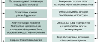
conclusions
The installation of new electricity meters by energy supply organizations also requires new approaches from electricity consumers who want to both reduce energy consumption and not pay for electricity that they have not actually consumed. All tips for this are given above in the article.
In addition to them, electricity consumers need to use energy saving methods. It is necessary to turn off lights, televisions, computers, etc., if there is no need to use them at a given time. This is especially true for the main energy hogs in the house - electric boilers.
Author: Nikolay Vlasyuk, Kiev Source: Electric magazine No. 1-2/2017
Calculation of power of electrical appliances
Determining the power of equipment is useful not only for calculating the energy consumed and saving it. It also helps to estimate the maximum load, and prevent fire if this number is exceeded.
Most device data sheets indicate power. If you multiply the indicated number in kW by the operating time, you can get the amount of electricity consumed. Next, it remains to figure out how to calculate electricity consumption based on the power of the equipment.
Let's say there are 2 light bulbs of 40 W each and a kettle with a power of 2.1 kW. The light bulbs work for 4 hours a day, and the kettle boils for 5 minutes. Let's say it is used 6 times a day. Then the light bulbs consume 320 W hours, and the kettle - 1.05 kW. The total consumption will be 1.37 kW.
Technical characteristics of electricity meters
Table 5.1. Technical parameters TsE6807B-1 (active energy meter)
| Accuracy class | 2,0 |
| Rated current, A | 5 |
| Maximum current, A | 50 |
| Rated voltage, V | 220 |
| Power consumption by parallel circuit, VA | 4 |
| Power consumption by series circuit, W | 0,05 |
| Power consumption by the tariff control circuit, W | — |
| Operating temperature range, °C | –45…+60 |
| Number of tariffs | 1 |
| Main output gear ratio | 500 |
| Gear ratio of verification output | 32000 |
Table 5.2. Technical parameters TsE6807B-2 (active energy meter)
| Accuracy class | 2,0 |
| Rated current, A | 5 |
| Maximum current, A | 50 |
| Rated voltage, V | 220 |
| Power consumption by parallel circuit, VA | 4 |
| Power consumption by series circuit, W | 0,05 |
| Power consumption by the tariff control circuit, W | 0,1 |
| Operating temperature range, °C | –45…+60 |
| Number of tariffs | 2 |
| Main output gear ratio | 500 |
| Gear ratio of verification output | 32000 |
Table 5.3. Technical parameters of SEB-2 (active energy meter)
| Accuracy class | 2,0 |
| Rated current, A | 5 |
| Maximum current, A | 50 |
| Rated voltage, V | 220 |
| Power consumption by parallel circuit, VA | 1,5 |
| Power consumption by series circuit, W | 0,1 |
| Power consumption by the tariff control circuit, W | 0,1 |
| Operating temperature range, °C | –45…+50 |
| Number of tariffs | 2 |
| Main output gear ratio | 500 |
| Gear ratio of verification output | 32000 |
Table 5.4. Technical parameters of SET4-1 (active energy meter)
| Accuracy class | 2,0 |
| Rated current, A | 5 |
| Maximum current, A | 60 |
| Rated voltage, V | 380/220 |
| Power consumption by parallel circuit, VA | 4 |
| Power consumption by series circuit, W | 0,3 |
| Power consumption by the tariff control circuit, W | — |
| Operating temperature range, °C | –40…+60 |
| Number of tariffs | 1 |
| Main output gear ratio | 200 |
| Gear ratio of verification output | 3200 |
Table 5.5. Technical parameters SET4-1/1 (active energy meter)
| Accuracy class | 2,0 |
| Rated current, A | 5 |
| Maximum current, A | 7,5 |
| Rated voltage, V | 380/220 |
| Power consumption by parallel circuit, VA | 4 |
| Power consumption by series circuit, W | 0,3 |
| Power consumption by the tariff control circuit, W | — |
| Operating temperature range, °C | –40…+60 |
| Number of tariffs | 1 |
| Main output gear ratio | 250 |
| Gear ratio of verification output | 4000 |
Table 5.6. Technical parameters SET4-1/2 (active energy meter)
| Accuracy class | 2,0 |
| Rated current, A | 10 |
| Maximum current, A | 100 |
| Rated voltage, V | 380/220 |
| Power consumption by parallel circuit, VA | 4 |
| Power consumption by series circuit, W | 0,3 |
| Power consumption by the tariff control circuit, W | — |
| Operating temperature range, °C | –40…+60 |
| Number of tariffs | 1 |
| Main output gear ratio | 200 |
| Gear ratio of verification output | 3200 |
Table 5.7. Technical parameters of SET4-2 (active energy meter)
| Accuracy class | 2,0 |
| Rated current, A | 5 |
| Maximum current, A | 60 |
| Rated voltage, V | 380/220 |
| Power consumption by parallel circuit, VA | 4 |
| Power consumption by series circuit, W | 0,3 |
| Power consumption by the tariff control circuit, W | 0,2 |
| Operating temperature range, °C | –40…+60 |
| Number of tariffs | 2 |
| Main output gear ratio | 200 |
| Gear ratio of verification output | 3200 |
Table 5.8. Technical parameters SET4-2/1 (active energy meter)
| Accuracy class | 2,0 |
| Rated current, A | 5 |
| Maximum current, A | 7,5 |
| Rated voltage, V | 380/220 |
| Power consumption by parallel circuit, VA | 4 |
| Power consumption by series circuit, W | 0,3 |
| Power consumption by the tariff control circuit, W | 0,2 |
| Operating temperature range, °C | –40…+60 |
| Number of tariffs | 2 |
| Main output gear ratio | 250 |
| Gear ratio of verification output | 4000 |
Table 5.9. Technical parameters SETA-1 (active energy meter)
| Accuracy class | 0,5 |
| Rated current, A | 1 |
| Maximum current, A | 1,5 |
| Rated voltage, V | 100/57,7 |
| Power consumption by parallel circuit, VA | 2 |
| Power consumption by series circuit, W | 0,05 |
| Power consumption by the tariff control circuit, W | — |
| Operating temperature range, °C | –40…+50 |
| Number of tariffs | 1 |
| Main output gear ratio | 10000 |
| Gear ratio of verification output | 640000 |
Table 5.10. Technical parameters SETA-1/1 (active energy meter)
| Accuracy class | 0,5 |
| Rated current, A | 5 |
| Maximum current, A | 7,5 |
| Rated voltage, V | 100/57,7 |
| Power consumption by parallel circuit, VA | 2 |
| Power consumption by series circuit, W | 0,05 |
| Power consumption by the tariff control circuit, W | — |
| Operating temperature range, °C | –40…+50 |
| Number of tariffs | 1 |
| Main output gear ratio | 10000 |
| Gear ratio of verification output | 640000 |
Table 5.11. Technical parameters SETA-1/2 (active energy meter)
| Accuracy class | 1,0 |
| Rated current, A | 1 |
| Maximum current, A | 1,5 |
| Rated voltage, V | 100/57,7 |
| Power consumption by parallel circuit, VA | 2 |
| Power consumption by series circuit, W | 0,05 |
| Power consumption by the tariff control circuit, W | — |
| Operating temperature range, °C | –40…+50 |
| Number of tariffs | 1 |
| Main output gear ratio | 10000 |
| Gear ratio of verification output | 640000 |
Table 5.12. Technical parameters SETA-1/3 (active energy meter)
| Accuracy class | 1,0 |
| Rated current, A | 5 |
| Maximum current, A | 7,5 |
| Rated voltage, V | 100/57,7 |
| Power consumption by parallel circuit, VA | 2 |
| Power consumption by series circuit, W | 0,05 |
| Power consumption by the tariff control circuit, W | — |
| Operating temperature range, °C | –40…+50 |
| Number of tariffs | 1 |
| Main output gear ratio | 10000 |
| Gear ratio of verification output | 640000 |
Table 5.13. Technical parameters of SETA-2 (active energy meter)
| Accuracy class | 0,5 |
| Rated current, A | 5 |
| Maximum current, A | 7,5 |
| Rated voltage, V | 100/57,7 |
| Power consumption by parallel circuit, VA | 2 |
| Power consumption by series circuit, W | 0,05 |
| Power consumption by the tariff control circuit, W | 0,2 |
| Operating temperature range, °C | –40…+50 |
| Number of tariffs | 2 |
| Main output gear ratio | 10000 |
| Gear ratio of verification output | 640000 |
Table 5.14. Technical parameters SETA-2/1 (active energy meter)
| Accuracy class | 1,0 |
| Rated current, A | 5 |
| Maximum current, A | 7,5 |
| Rated voltage, V | 100/57,7 |
| Power consumption by parallel circuit, VA | 2 |
| Power consumption by series circuit, W | 0,05 |
| Power consumption by the tariff control circuit, W | 0,2 |
| Operating temperature range, °C | –40…+50 |
| Number of tariffs | 2 |
| Main output gear ratio | 10000 |
| Gear ratio of verification output | 640000 |
Table 5.15. Technical parameters of SETAM 005 (meter for measuring half-hour energy peaks)
| Accuracy class | 1,0 |
| Rated current, A | 5 |
| Maximum current, A | 7,5 |
| Rated voltage, V | 100/57,7 |
| Power consumption by parallel circuit, VA | 10 VA/2 W |
| Power consumption by series circuit, W | 4 |
| Power consumption by the tariff control circuit, W | — |
| Operating temperature range, °C | –40…+45 |
| Number of tariffs | 3 |
| Main output gear ratio | 1600 |
| Gear ratio of verification output | 102400 |
Table 5.16. Technical parameters SETAM 005-01 (meter for measuring half-hour energy peaks)
| Accuracy class | 1,0 |
| Rated current, A | 5 |
| Maximum current, A | 7,5 |
| Rated voltage, V | 380/220 |
| Power consumption by parallel circuit, VA | 10 VA/2 W |
| Power consumption by series circuit, W | 4 |
| Power consumption by the tariff control circuit, W | — |
| Operating temperature range, °C | –40…+45 |
| Number of tariffs | 3 |
| Main output gear ratio | 400 |
| Gear ratio of verification output | 25600 |
Table 5.17. Technical parameters SETAM 005-02 (meter for measuring half-hour energy peaks)
| Accuracy class | 2,0 |
| Rated current, A | 5 |
| Maximum current, A | 50 |
| Rated voltage, V | 380/220 |
| Power consumption by parallel circuit, VA | 10 VA/2 W |
| Power consumption by series circuit, W | 2,5 |
| Power consumption by the tariff control circuit, W | — |
| Operating temperature range, °C | –40…+45 |
| Number of tariffs | 3 |
| Main output gear ratio | 200 |
| Gear ratio of verification output | 12800 |
Table 5.18. Technical parameters SETAM 005-03 (meter for measuring half-hour energy peaks)
| Accuracy class | 2,0 |
| Rated current, A | 10 |
| Maximum current, A | 100 |
| Rated voltage, V | 380/220 |
| Power consumption by parallel circuit, VA | 10 VA/2 W |
| Power consumption by series circuit, W | 2,5 |
| Power consumption by the tariff control circuit, W | — |
| Operating temperature range, °C | –40…+45 |
| Number of tariffs | 3 |
| Main output gear ratio | 100 |
| Gear ratio of verification output | 6400 |
Table 5.19. Technical parameters SETARP-1/1 (reversible active-reactive energy meter)
| Accuracy class | 1,0 / 2,0 |
| Rated current, A | 5 |
| Maximum current, A | 7,5 |
| Rated voltage, V | 100/57,7 |
| Power consumption by parallel circuit, VA | 2 |
| Power consumption by series circuit, W | 0,05 |
| Power consumption by the tariff control circuit, W | — |
| Operating temperature range, °C | –40…+50 |
| Number of tariffs | 1 |
| Main output gear ratio | 10000 |
| Gear ratio of verification output | 640000 |
Table 5.20. Technical parameters SETR-1 (reactive energy meter)
| Accuracy class | 1,0 |
| Rated current, A | 1 |
| Maximum current, A | 1,5 |
| Rated voltage, V | 100/57,7 |
| Power consumption by parallel circuit, VA | 2 |
| Power consumption by series circuit, W | 0,05 |
| Power consumption by the tariff control circuit, W | — |
| Operating temperature range, °C | –40…+50 |
| Number of tariffs | 1 |
| Main output gear ratio | 10000 |
| Gear ratio of verification output | 640000 |
Table 5.21. Technical parameters SETR-1/1 (reactive energy meter)
| Accuracy class | 1,0 |
| Rated current, A | 5 |
| Maximum current, A | 7,5 |
| Rated voltage, V | 100/57,7 |
| Power consumption by parallel circuit, VA | 2 |
| Power consumption by series circuit, W | 0,05 |
| Power consumption by the tariff control circuit, W | — |
| Operating temperature range, °C | –40…+50 |
| Number of tariffs | 1 |
| Main output gear ratio | 10000 |
| Gear ratio of verification output | 640000 |
Table 5.22. Technical parameters SETRP-1 (reversible reactive energy meter)
| Accuracy class | 1,0 |
| Rated current, A | 1 |
| Maximum current, A | 1,5 |
| Rated voltage, V | 100/57,7 |
| Power consumption by parallel circuit, VA | 2 |
| Power consumption by series circuit, W | 0,05 |
| Power consumption by the tariff control circuit, W | — |
| Operating temperature range, °C | –40…+50 |
| Number of tariffs | 1 |
| Main output gear ratio | 10000 |
| Gear ratio of verification output | 640000 |
Table 5.23. Technical parameters SETRP-1 (reversible reactive energy meter)
| Accuracy class | 1,0 |
| Rated current, A | 1 |
| Maximum current, A | 1,5 |
| Rated voltage, V | 100/57,7 |
| Power consumption by parallel circuit, VA | 2 |
| Power consumption by series circuit, W | 0,05 |
| Power consumption by the tariff control circuit, W | — |
| Operating temperature range, °C | –40…+50 |
| Number of tariffs | 1 |
| Main output gear ratio | 10000 |
| Gear ratio of verification output | 640000 |
Table 5.24. Technical parameters PSCh-4P1 (reversible active energy meter)
| Accuracy class | 0,5 |
| Rated current, A | 1 |
| Maximum current, A | 1,5 |
| Rated voltage, V | 100/57,7 |
| Power consumption by parallel circuit, VA | 1 |
| Power consumption by series circuit, W | 0,05 |
| Power consumption by the tariff control circuit, W | — |
| Operating temperature range, °C | –40…+50 |
| Number of tariffs | 1 |
| Main output gear ratio | 10000 |
| Gear ratio of verification output | 640000 |
Table 5.25. Technical parameters PSCh-4P1 (reversible active energy meter)
| Accuracy class | 0,5 |
| Rated current, A | 1 |
| Maximum current, A | 1,5 |
| Rated voltage, V | 100/57,7 |
| Power consumption by parallel circuit, VA | 1 |
| Power consumption by series circuit, W | 0,05 |
| Power consumption by the tariff control circuit, W | — |
| Operating temperature range, °C | –40…+50 |
| Number of tariffs | 1 |
| Main output gear ratio | 10000 |
| Gear ratio of verification output | 640000 |
Table 5.26. Technical parameters PSCh-4P2 (reversible active energy meter)
| Accuracy class | 0,5 |
| Rated current, A | 5 |
| Maximum current, A | 7,5 |
| Rated voltage, V | 100/57,7 |
| Power consumption by parallel circuit, VA | 1 |
| Power consumption by series circuit, W | 0,05 |
| Power consumption by the tariff control circuit, W | — |
| Operating temperature range, °C | –40…+50 |
| Number of tariffs | 1 |
| Main output gear ratio | 10000 |
| Gear ratio of verification output | 640000 |
Converting amperes to kilowatts
In some cases, only one number may be indicated in the passport or on the device itself - current (amps). To get watts from this parameter, simply multiply it by voltage. If the voltage is not specified, then the value is 220 V (for devices designed for operation in Europe or Russia). This calculation method will be correct for most household electrical appliances.
It's worth noting that when you multiply volts by amps, you get watts, not kilowatts. To find out the value of the latter, you need to divide the resulting value by 1000.
Methods for calculating the amount of payment for electricity
According to the electricity meter
This is the simplest and most popular method.
According to the single-rate system, you need to multiply the amount of electricity consumed by the rate per kilowatt-hour.
Using a two-tariff meter, you need to multiply the amount of electricity consumed at night by the night rate of kilowatt-hours and add this with the product of the amount of electricity consumed during the day by the daily rate of kilowatt-hours.
Using a multi-tariff meter, you need to add the products of 3 terms: the amount of electricity consumed at peak per kilowatt-hour rate at peak, the amount of electricity consumed during half-peak at the kilowatt-hour rate at half-peak, and the amount of electricity consumed at night at the night rate of one kilowatt-hour.
Payment taking into account social consumption standards
In 2012, the government of the Russian Federation established a social norm for electricity consumption in a number of regions. It is calculated from the place of residence, the number of residents and changes according to the seasons. The system has two tariffs: for paying for electricity that does not go beyond the social norm and a tariff for paying for electricity that goes beyond the social norm.
Thus, to calculate the amount of payment for electricity, you need to add the products of two data: the amount of electricity consumed that does not exceed social norms multiplied by the kilowatt-hour rate that does not exceed the social norm and the amount of electricity consumed in excess of the social norm by the kilowatt-hour rate that exceeds the social norm .
Payment without electricity meter data
To understand what formula will be used to calculate payment without electric meter data, you need to know the reason for the lack of data.
The electricity meter is missing or its data has not been transmitted for more than 6 months.
The payment amount will be equal to the product of the number of people registered in the territory by the consumption standard established in the region, by the approved tariff in the region and by the increasing factor for consumers who do not have an individual meter, but have the opportunity to install one.
The meter is not corrected or the readings are not transmitted on time.
In such a situation, the average electricity consumption for six and three months is calculated. Those. the amount of electricity consumed for six (three) months is divided by the number of months and multiplied by the tariff established in the region.
How to correctly take readings from the meter is written in our article.
Using a common house meter for measuring consumed electricity
It is necessary to subtract from the volume of consumption in the entire house the sum of the volume of consumption in non-residential premises, in apartments with and without meters, multiply by the quotient between the area of the apartment and the area of all residential and non-residential premises and multiply the result by the tariff established for the given region.
Without the help of a communal meter
It is necessary to multiply the general house rate of electricity consumption by the area of all used premises in the house, multiply by the quotient between the area of the apartment and the area of all residential and non-residential premises and multiply the result by the tariff.
Calculation of electricity by power
Each electrical appliance indicates its power.
Next, we find out which device works for how many hours, just as with power, we determine the average value of its operation per day and multiply it by the average value of its power. This is where the electricity it consumes comes from.
To determine how much total electricity was spent over a certain period of time, you need to add up the data for each device and divide by 1000 (since electricity is paid in kW/h, and the power on devices is indicated in W). We multiply the resulting number by the number of days for which electricity payments are made. Then, we multiply the result by the tariff and get the amount to pay for electricity.
In order to avoid getting into a difficult situation with paying for electricity, you need to take into account all factors, monitor changes in tariffs and systematically check the serviceability of metering devices.
Methods for calculating electricity consumption of household appliances
Advantages and disadvantages of night electricity tariff
How to correctly take readings from an electricity meter?
How to choose the right one and which one is better to install an electric meter in an apartment
Electric meter verification: verification period and verification interval
How to change the electricity meter in an apartment or private house?
Measuring consumption by the device
It will not be possible to find out exactly the real consumption using only the formula. You can use an electricity meter in principle. But the most convenient option is a special meter for the outlet. It is quite common and often found on sale; you can find it by its name - energy meter, or wattmeter.
Using such a measuring device, you can obtain the following data:
- cost of electricity consumption per month when setting tariffs;
- voltage and current at the moment;
- current power;
- consumption for a given period of time.
To start measuring, just plug the wattmeter into a power outlet. It also has a socket. The measuring devices are connected there. Once connected, power, voltage, current, consumption and other indicators will be displayed in real time, depending on the settings.
Operating principle of an inductive electricity meter
Naturally, with constantly changing loads, monitoring the readings of a wattmeter with a stopwatch would be extremely impractical. Therefore, they came up with a device (electricity meter), where the moment of force arising from the electromagnetic interaction of voltage and current coils is used to rotate the drive of the counting mechanism. Theoretically, we can assume that the voltage in the network does not change, which means that the change in the strength of the electromagnetic interaction of the coils is directly proportional to the current of the connected load.
Induction counter - inside view
The counters use an aluminum disk as a drive for the counting mechanism, where voltage and current coils induce eddy currents, the electromagnetic field of which interacts with the magnetic fields of these coils, creating a torque.
Therefore, electromagnetic mechanical counters are also called induction counters. In an induction electric meter, the magnetic circuits of the current and voltage coils are placed at an angle of 90º and form a gap in which an aluminum disk is placed, which makes it possible to create a moment of force in it for its rotation.
Induction electricity meter device
It is known from school physics that a force constantly acting on a body without interference causes it to accelerate to infinity. Thus, in an ideal counter mechanism (without friction), constant power would spin the disk to infinite revolutions. Therefore, the electric meter device has a permanent magnet to brake the aluminum disk of the counting device drive.
Since aluminum is a non-magnetic metal, the braking force depends only on the speed of rotation of the disc. Correctly setting the balance between the accelerating force of the disk and the braking torque allows you to establish the dependence of the rotation of the counting mechanism drive only on the power consumption and eliminate self-propulsion and rotation in the opposite direction. Induction single-phase and three-phase electric energy meters, which have two aluminum disks on one shaft, operate on this principle.
Three-phase induction electricity meter
Advantages and disadvantages of induction electricity meters
The counter mechanism described above has been used in various models of electricity meters for many decades due to the simplicity and reliability of the design. A voltage coil having many turns, wound with a thin wire, with a diameter of 0.06 - 0.12 mm, is highly resistant to long-term overvoltages - very often single-phase electric meters were under a voltage of almost 380V due to a zero break, but subsequently continued to work properly.
The current coil has several turns with a cross-section sufficient to withstand the short-circuit current. Since induction electricity meters do not contain other electrical elements or radio components, they are very resistant to voltage surges and the electromagnetic influences of lightning strikes. A simple and cheap counting mechanism, consisting of a worm gear on the shaft of an aluminum disk and a digital drum, allows induction meters to serve regularly for decades in difficult climatic conditions.
A simple device for the counting mechanism of an induction electric meter
Due to imperfect design, friction and aging of mechanisms, induction electricity meters have significant disadvantages:
- low accuracy class;
- large error, increasing at low load currents;
- significant own electricity consumption;
- lack of reactive energy metering for household meters;
- Electrical energy is taken into account only in one direction;
- there is no protection against hacking, interference with work and theft of electricity.
The seal on an outdated induction electric meter is the only protection against unauthorized access to the inside of the housing. Most of the disadvantages of induction meters described above benefit their owners, since electricity is metered with an error that is beneficial for the recipient. Many ways have been invented to deceive an induction meter. Therefore, many electricity suppliers are trying to replace outdated, unprofitable electricity meters for their consumers with new, more accurate hybrid or electronic electricity meters. In some countries, obsolete inductive electricity meters are forced to be replaced free of charge.
Computer
The main source of consumption is the system unit. It has a power supply installed, and once you know its power characteristics, you can estimate the approximate consumption. As a rule, this is 300-600 W. But this is the maximum power; it is unlikely that the computer will only consume even under full load.
Additionally, you need to take into account the monitor and other equipment, if it is turned on (printer, scanner, modem, speakers). In total, for an average computer, consumption is about 550 W (0.55 kW). But taking into account downtime and performing simple tasks, the average value is taken - 0.5 kW. It turns out that if you use a computer for 6 hours a day, then it consumes about 90 kWh per month. Accordingly, if the computer does not turn off around the clock, then its maximum monthly consumption will exceed 300 kWh.
Selecting a machine by power
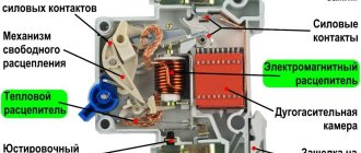
Everyone knows that electricity is not something to joke about. Incorrect calculation of the power supply circuit can lead to at least two unpleasant consequences. The first is when, when several energy-intensive electrical appliances (for example, a washing machine, electric kettle and iron) are turned on, the circuit breakers trip and the network is de-energized. Unpleasant, but not fatal. The second is when, when you turn on the same devices, the automatic devices will not work, and the electrical wiring will begin to melt and smoke. And this is already a mortal danger: there is only one step to a fire. That is why choosing a machine based on load power is of paramount importance.
Automatic single-pole switch Schneider BA63 1P 25A C for 25 amperes.
A little theory
It is known from the physics course that there is a relationship between electrical power, current strength and voltage in the electrical network. In a simplified form, this relationship is expressed by the following formula for a single-phase network:
where W is the current power in watts (W);
I – current strength in amperes (A);
V – voltage in volts (V).
In this case, we will be interested in the current strength, since the circuit breaker and electrical wiring characteristics are often selected based on this parameter. For convenience, we transform the above formula into the expression:
As an example, let’s calculate the current strength for the load that the energy-intensive consumers mentioned above provide to the power grid. Their total power will be about 6 kW, and at a voltage of 220 V we get the current in the circuit:
I = 6000 W / 220 V = 27.3 A
For a three-phase connection diagram, formula (2) will take the following form:
This change is caused by the fact that with an equal load and uniform distribution of power across phases, the current in a three-phase network will be three times less. Thus, with the same total power of 6 kW, but at a voltage of 380 V, the current in the circuit will be equal to:
I = 6000 W / (1.73 x 380 V) = 9.1 A
Having received this indicator, you can begin to select a circuit breaker that provides network overload protection.
Selection of circuit breaker rating for current and load power
To select a suitable machine, it is convenient to calculate the current per kilowatt of load power and draw up the corresponding table. Applying formula (2) and a power factor of 0.95 for a voltage of 220 V, we obtain:
1000 W / (220 V x 0.95) = 4.78 A
Considering that the voltage in our electrical networks often does not reach the required 220 V, it is quite correct to take the value of 5 A per 1 kW of power. Then the table of current versus load will look like this in Table 1:
| power, kWt | 2 | 4 | 6 | 8 | 10 | 12 | 14 | 16 |
| Current strength, A | 10 | 20 | 30 | 40 | 50 | 60 | 70 | 80 |
This table gives an approximate estimate of the strength of alternating current flowing through a single-phase electrical network when household electrical appliances are turned on. It should be remembered that this refers to peak power consumption, not average. This information can be found in the documentation supplied with the electrical product. In practice, it is more convenient to use the table of maximum loads, which takes into account the fact that machines are produced with a certain current rating (Table 2):
| Connection diagram | Current ratings of automatic machines | |||||||
| 10 A | 16 A | 20 A | 25 A | 32 A | 40 A | 50 A | 63 A | |
| Single-phase, 220 V | 2.2 kW | 3.5 kW | 4.4 kW | 5.5 kW | 7.0 kW | 8.8 kW | 11 kW | 14 kW |
| Three-phase, 380 V | 6.6 kW | 10,6 | 13,2 | 16,5 | 21,0 | 26,4 | 33,1 | 41,6 |
For example, if you need to find out how many amperes a machine needs for a power of 15 kW with a three-phase current, then we look in the table for the nearest larger value - it is 16.5 kW, which corresponds to a machine with a capacity of 25 amperes.
In reality, there are limitations on the allocated power. In particular, in modern urban apartment buildings with an electric stove, the allocated power is from 10 to 12 kilowatts, and a 50 A automatic machine is installed at the entrance. It is reasonable to divide this power into groups, taking into account the fact that the most energy-intensive appliances are concentrated in the kitchen and bathroom. Each group is equipped with its own machine, which eliminates the complete loss of power to the apartment in the event of an overload on one of the lines.
Fridge
According to the technical data sheet of most refrigerators, they consume about 230-450 kWh per year. It is enough to divide this number by 12 to get a monthly consumption of about 20-30 kW. It will vary depending on the size of the refrigerator, the presence of a freezer, the density of the rubber bands, the presence of energy-saving modes and the food load. Also, to assess consumption, it is necessary to take into account external conditions. It will directly depend on the air temperature in the room.
How does an induction meter work?
The essence of the operation of induction electricity meters is based on the principle that a moving part is simultaneously affected by a rotating and braking torque. This moment is proportional to the accounting value, the braking moment is proportional to the speed of rotation of the moving part. An induction single-phase electricity meter consists of several elements:
- Voltage coils that are located on the magnetic circuit;
- Aluminum rotation disc;
- Transmission mechanism of the metering device;
- Current coils on the magnetic circuit;
- Permanent magnet.
The coil is made of wire with a large cross-section, which can withstand a large load. Coil turns are available in small quantities, usually 13-30 turns per coil. They are distributed in a uniform position on two magnetic cores, which have a U shape and are made of electrical steel. The core works to create a certain concentration of magnetic flux, which crosses the counting disk and rotates it.
The voltage winding is connected to the mains voltage phase and always has an operational state, along with the consumer, which is why it is called a parallel circuit. A voltage coil is required to produce a magnetic flux that will be proportional to the mains voltage. It has certain design differences from the current coil in that it has more turns, about 8000 - 12,000, and a small conductor cross-section of 0.1 - 0.15 mm2. In large numbers, the turns create a higher inductive reactance than the active resistance of the winding, which is quite important for complying with the 90° shift rule and makes it possible to reduce electricity consumption on a single-phase meter.
The magnetic flux of the current coil and the voltage coil that pass along the disk form transformation currents in it, due to which a rotating torque is created. To create a counter torque that will be proportional to the speed of the disc, permanent brake magnets are used, whose magnetic flux crosses the rotating disc of electrically conductive material.
The cutting currents generated in the disk always maintain the rotation speed in proportion to the disk. That is, when the meter operates, it follows a certain pattern: the greater the power consumption, the faster the disk will rotate along its axis. The reaction moment, which is formed when the magnetic flux interacts with the disk current, will always be proportional to the rotation speed. When the disk passes the wave that creates the braking magnet, a cutting emf is induced on it, which comes from the middle of the disk. The flux force of the braking magnet, when interacting with the disk current, is directly proportional to the cutting emf and has a direction opposite to the movement of the disk. The slowing down process depends on the distance of the magnet from the center of the disk, defined as the product of the leverage and the value of the force. That is, the rotation speed is adjusted by moving the magnet, which allows you to adjust it depending on the gear ratio.
For more precise adjustments, special adjustment devices are used on the meters. These devices are short-circuited copper, aluminum turns, or a winding of turns of copper wire that is closed to an adjustable resistance.
Learn from other people's mistakes
In the early 1990s, foreign manufacturers of measuring products were overwhelmed by approximately the same euphoria that Russia is now experiencing. For example, in England the share of electronic electricity meters has reached 95%, however, today this figure has decreased to 65%.
From Europe, induction meter factories have moved to developing countries and are producing millions of meters that find a niche and fulfill their function.
Russian energy systems (Krasnoyarskenergo, Tatenergo, Bryanskenergo) consistently purchase induction meters in the same way as electronic ones, giving preference to their reliability and taking into account the poor quality of networks, especially in rural areas. After all, the service life of an induction meter is tens of years, and even after 50 years, some samples will correspond to the given accuracy class.
The problem of choosing an induction or electronic meter is somewhat far-fetched. They are intended for different market sectors.
It is too early to abandon the use of induction meters. Just like you shouldn't underestimate electronic
First of all, you need to decide whether it is possible and necessary to take advantage of all the advantages of meters and not pay attention to their disadvantages?
The choice of a meter is the result of a balanced decision and analysis of a particular situation.
TV
Consumption by TVs differs depending on their design and screen diagonal. So, for example, on average a small TV will “eat” 100 W, while a plasma with a large diagonal will already consume 300 W or even 500 W. You also need to take into account the time you watch TV, whether any additional devices are used (for example, receivers) and how many TVs are installed in the apartment. It is estimated that if the TV is turned on for about 4 hours a day, it consumes approximately 20-30 kWh monthly.
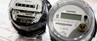
How to take readings
Depending on the model of the electricity meter, different methods for obtaining information are used.
Old meters
Mechanical induction devices have been popular for quite some time. At the moment, they are gradually giving way to electronic IPUs, which provide better control of electricity consumption. Although the demand for classic meters is gradually decreasing, they are still found in private houses and apartments.
The device is single-tariff (single-phase), so there is no need to perform complex calculations to take readings. It is recommended to select a conditional day of each month for writing off data from the electric meter, preceding or included in the period for submitting information.
The procedure is quite simple:
- A standard mechanical apparatus has a dial with 5–7 digits, and as it works, the numbers change from 0 to 9. After one department has completed a full revolution, the next one begins. The dial is divided into two halves: the left one shows how many kW/h have been consumed since connection, the second (red) is separated by a comma and indicates tenths (hundredths) of a kilowatt.
- It is necessary to write off the main part of the characters 000024.8 (seven-digit order). The basis is 000024 kW/hour.
- Depending on the requirements of the management company or resource supplying organization, the information received must be submitted without changes or the difference between the current and previous values must be independently calculated. So, if over the past month the readings were 000003, then: 000024–000003=21 kW/h.
In both old and new mechanical electricity meters, the numbers that are not taken into account in the calculations are clearly highlighted at the end of the number row
The process may be difficult due to the counter resetting to zero after reaching the maximum value. In such a situation, you must first write down the old data. For example, for May (conditionally) it was 999969 (without a decimal point), the new information is 000003 (1 is substituted at the beginning, the result is 1,000003).
1 000003–999969=34 kW/h (current readings).
It is necessary to understand that any illegal attempts to change information about electricity consumption will lead to serious trouble.
New counters
Modern single- and three-phase metering devices differ significantly from mechanical ones. The main difference is that IPUs are equipped with an electronic dial and can be multi-tariff, which provides significant savings in energy consumption. To correctly determine the readings, you need to understand the available devices.
The following varieties are distinguished:
- single tariff, the readings of which are not divided into zones;
- two-tariff – T1/T2;
- three-tariff – T1/T2/T3.
Data is collected from such devices as follows:
- You need to press a button on the mechanism body. It can be called differently, depending on the IPU model, most often - “PRSM”, “Input” or “Frame”.
- After pressing, the required values sequentially appear, which have the corresponding signatures - T1, T2 or T3.
- The main current indicators of 5–6 digits to the decimal point are written off one by one, depending on the type of counter.
- On an electronic display, the characters are separated by a noticeable comma, and in some IPUs the hundredths and tenths are significantly smaller.
- The information is transmitted directly to the management company or supplying organization or calculated independently.
In electric meters with an electronic display, after pressing the control key, the data is displayed on the screen: the number of kilowatt-hours consumed and the tariff number (indicated in the upper left corner)
Explanation of symbols for various electronic devices:
- Single tariff. Reflect the total resource consumption without division.
- Two-tariff. T1 – day zone (from 7 am to 11 pm), T2 – night period (from 23.00 to 7.00).
- Three-tariff. T1 – peak zone, which has two time periods: from 7.00 to 10.00 and 17.00 to 21.00; T2 – night (from 23.00 to 7.00); T3 – half-peak zone (from 10.00 to 17.00 and from 21.00 to 23.00). Time periods may vary by region.
The multi-tariff IPU must be correctly connected and pre-configured so that it records readings exactly for the allotted period. In some situations, this may require agreement with the utility provider.
Before purchasing and connecting multi-tariff meters, you should consult your energy supply company about the possibility of using them in your region
Washing machine
The consumption of a washing machine is usually specified in the passport. The numbers depend on the program and are indicated not for hourly consumption, but for the entire cycle. The power of an average device is 2-2.5 kW; in practice, 1.5 kW*hour is consumed per hour. When using a washing machine twice a week with a 2-hour cycle, you get about 20 kWh.
However, this figure will be higher if the washing machine has a drying mode, the family is large or there are small children.
Kettle and iron
These devices are considered the most expensive in terms of energy costs. Despite the fact that they do not work for long, the consumption for both devices is still about 30 kWh per month.
Not all appliances that consume electricity in the house are listed. Additionally, you will need to count such things as a multicooker, microwave oven, vacuum cleaner, phone chargers and others, if available. Maximum consumption is observed if an electric or induction stove, air conditioner, boiler or electric heaters are used.
Warm floor
This type of heating is considered one of the most economical, even if electricity is used for heating. However, consumption depends on many factors, such as operating mode, desired air temperature in the room, outdoor air temperature, types of coatings, and so on. It is believed that if a heated floor is used instead of the main heating device, then it consumes about 0.2 kW per 1 sq.m. per hour. m. If it is used only to maintain a comfortable temperature, in the presence of other heat sources, then this figure will be approximately half as much. In order to calculate the monthly consumption, it is necessary to multiply this figure by the heated area, daily operating time and the number of days in the month.
Cost of electricity consumption
To estimate the amount you will have to pay for electricity, you need to know the average cost for your region of residence. Let’s say this figure is 4 rubles per kW*hour.
Next, you should multiply the resulting number (from the monthly meter) by the price. For example: consuming 100 kWh of electricity per month will cost 400 rubles.
There are many online calculators that can help you calculate this figure more accurately. The cost may depend on some other criteria: the presence of a multi-tariff meter, benefits, total monthly consumption, and so on.
How to take readings from electronic meters
Electronic meters have become widespread in recent years. They are widely used to replace meters whose verification interval has expired. The display on such devices is electronic, like on a calculator. For the convenience of consumers, manufacturers often write out fractions of kW in smaller font and always separate them with a period or comma.
The rules for taking readings are the same as for induction models - the last two digits after the decimal point and the zeros on the left are not taken into account. But there are also fundamental differences between electronic meters, because they are able to calculate the amount of electricity consumed by time of day - by zone. These are multi-tariff metering devices, and taking readings from them has its own characteristics.
Multi-tariff metering device "Mercury 200"
At different times of the day, the resource supply company sets differential tariffs. Multi-tariff devices calculate energy consumption in each time period determined by the tariff zone. From such meters, readings are taken for each zone using the functions of the device:
- in automatic mode, the value of energy consumed in kilowatts per hour for each zone lights up on the screen within a few seconds;
- in manual mode - by pressing the “Enter” button, the consumer himself sorts through the readings by zone. Switching from tariff to tariff occurs every time you press the button.
First the time is displayed, then the date, then the readings for each tariff. The name of the tariff zone is displayed on the board at the top left. Depending on the model, from two to four zones appear: T1, T2, T3 or T4. After going through all the values, the display displays the total electricity consumption.
Meters supplied by JSC Electrotechnical
The principle of obtaining data from devices produced by the Russian Federation is the same as in the case of Mercury. The manufacturer offers two-tariff “day-night” or multi-tariff devices. Depending on the model, there are two or three buttons on the front panel. Scrolling through the values is done with the PRSM button, which means “view”. Otherwise, the algorithm for taking readings is the same. Payment is calculated based on full kWh, so the numbers after the dot are not taken into account and, accordingly, are not rewritten.
Electricity meter "Mikron"
Nizhny Novgorod NPO named after. Frunze supplies Mikron multi-tariff meters to the market. For the convenience of consumers, the developers have equipped the device with just one button for switching readings and have pre-designated tariff zones from T1 to T4 on the bottom border of the screen, and to the left of them there is another symbol - R+.
The readings will light up on the indicator for each zone in turn. The zone number will be indicated by a check mark. The same check mark will appear above the R+ symbol - this means that you can already rewrite the numbers. To see the next tariff value, press the button and wait until two checkmarks appear again. Mercury displays values in whole kW per hour and fractions with two digits after the dot. You only need to record the numbers up to the point.
Saiman counters
Another popular PU was developed by Saiman Corporation LLP. Consumers are invited to install simple devices under the Saiman brand in their apartments. All electricity consumption readings in these meters are displayed automatically, and there are no buttons for scrolling through the screens. The display shows information in the following sequence:
- current date yyyy.mm.dd;
- time of day hh.mm.ss;
- meter number;
- gear ratio (imp/kW•h), for single-phase 1,600;
- energy consumption readings: only TOTAL, if the control unit is single-tariff;
- alternately T1, T2, TOTAL (total amount), if the PU is of the day/night type, or two-tariff.
Only the whole part of the number is written down; the numbers after the decimal point are given for informational purposes.
Energy Saving Tips
Having analyzed energy costs, many owners involuntarily wonder if it is possible to somehow reduce them? Typically, large consumption is affected by refrigerators and lamps.
To reduce the consumption of a refrigerator, it must be moved away from the wall so that it is better ventilated, or replaced with a new one with better consumption readings.
It is optimal to use energy-saving light bulbs. They come in two types: LED and mercury. The latter are cheaper, but less durable, have lower efficiency and require special disposal rules. LED lamps are the best option. Provided they are made with high quality, they last a long time, can be produced in different colors, adjustable power, and as a rule, the manufacturer gives them a long warranty.
How to take readings correctly
According to the principle of operation, counters can be induction (they are also called mechanical and disk) or electronic. The first option is already considered outdated, but sometimes occurs. Disk meters can be quite noisy, their accuracy is low, and they can only work in one tariff zone. The readings of induction metering devices, the accuracy class of which is more than 2.0, have long been considered invalid and require mandatory replacement.
Electronic devices for monitoring electricity consumption can have a wide range of options and several tariff zones, they are silent in operation, and the accuracy of readings is several times higher than that of induction analogues.
Electricity meter readings are taken to the decimal point, regardless of whether the device is electronic or mechanical. Usually these are the first five or four digits. Another color, often red, indicates a tenth of one kilowatt, and it does not need to be included in the receipt for payment for lighting.
In multi-tariff metering devices, to take data, you must switch according to the readings using the “Enter” button or in another way, depending on the device model. Tariff zones differ by the time of day, when the price for electricity is higher and when it is lower.
At night, electricity is inexpensive, but during the day the cost of one kilowatt is several times higher. There may also be another, third tariff zone, which divides the day into “Peak” and “Half-peak”:
- T1 - “Day” or “Peak”;
- T2 - “Night”;
- T3 - “Half Peak”.
Tariffs depending on the time of day
Since energy consumption drops significantly at night, which complicates the operation of power plants, programs have been developed that allow you to pay less during the least busy period. This was done so that when installing a two- or three-tariff meter, people would use some of their electrical appliances at night and save money, while the load on the networks would be distributed more evenly.
In most regions there are two- or multi- (most often three-) tariff zones. In the first case (2-tariff zones), the cost of electricity at night falls by 2 times compared to the standard tariff. In the second, three tariff zones are distinguished. The first is night with a coefficient of 0.4. The second is half-peak with a coefficient of 1. The third is peak, with a coefficient of 1.5. Thus, for consumption in the night zone you need to pay 40% of the standard tariff, and in the peak zone - one and a half times more.
To use this type of tariffing, special electronic meters are required, in which meter readings are given separately for each zone. Some of them send the received data to the controller automatically, and, accordingly, the correct payment is received without the need to enter readings manually.
In order to understand how to calculate metered electricity consumed according to the principle of several tariffs, it is necessary to take the values for each tariff zone, multiply them by the standard tariff and by the normalization coefficient. The amount of consumption for all tariffs must be equal to the total consumption, which is also indicated on the meter.
The latter helps ensure that the calculations are made correctly.
Microprocessor single-phase/three-phase electricity meter "Delta"
Manufacturer of microprocessor single-phase/three-phase electricity meter - ABB VEI Metronica. Designed for metering electricity in single-phase or three-phase networks of residential buildings and industrial premises.
Technical specifications:
The external control mode is multi-tariff (up to four tariffs); Rated voltage 3x230/400 V, 3x57/100 V, 230 V; Maximum current 65 A;
Accuracy class 1.0 and 2.0;
Operating temperature range from –40 to +50 °C;
Direct and transformer connection, and they are programmed for measurements taking into account transformation ratios;
Dimensions - 123x100x65 mm; Weight - 0.5 kg.
The Delta microprocessor electricity meter is the smallest and, perhaps, the most elegant electricity meter. All readings are displayed on a liquid crystal display, and display modes are switched using a button or photosensitive element. Next to this element on the front panel there is a pulse LED operating status indicator.
Operation: the selection of information displayed on the display is carried out using two buttons located under the sealable cover (this should be done by the energy sales or energy supervision controller). To switch display operating modes, just shine a simple flashlight on the photosensitive element.
Such a perfect electronic device fits well into ASKUE, which provides constant monitoring of readings, switches tariffs and issues bills. You can benefit from the availability of preferential tariffs without an automated system if you connect a tarifficator (digital electronic time relay) to the meter. One rater can simultaneously service up to 100 Delta meters.
The manufacturer guarantees the service life of the electricity meter
“Delta” is at least 30 years old, the calibration interval is 8 years. The device has no mechanical parts, which increases its reliability.