Neutrals of electrical installations are the common points of the windings of generators or transformers connected in a star.
The type of connection of the neutrals of machines and transformers with the ground largely determines the level of insulation of electrical installations and the choice of switching equipment, the values of overvoltages and methods of limiting them, currents during single-phase ground faults, operating conditions of relay protection and safety in electrical networks, electromagnetic influence on communication lines and etc.
Depending on the neutral mode, electrical networks are divided into four groups:
- networks with ungrounded (isolated) neutrals;
- networks with resonantly grounded (compensated) neutrals;
- networks with effectively grounded neutrals;
- networks with solidly grounded neutrals.
In Russia, the first and second groups include networks with a voltage of 3-35 kV, the neutrals of transformers or generators of which are isolated from the ground or grounded through grounding reactors.
Networks with effectively grounded neutrals are used for voltages above 1 kV. In them, the earth fault coefficient does not exceed 1.4. The earth fault coefficient is the ratio of the potential difference between the undamaged phase and the earth at the point of earth fault of the damaged phase to the potential difference between the phase and the earth at this point before the fault. In accordance with the recommendations of the International Electrotechnical Committee (IEC), effectively grounded networks include high and ultra-high voltage networks, the neutrals of which are connected to the ground directly or through a small active resistance. In the Soviet Union, this group includes networks with voltages of 110 kV and higher.
The fourth group includes networks with voltages of 220, 380 and 660 V.
The operating mode of the neutral determines the ground fault current. Networks in which the single-phase ground fault current is less than 500 A are called networks with low ground fault currents (mainly networks with ungrounded and resonantly grounded neutrals). Currents of more than 500 A correspond to networks with high ground fault currents (these are networks with effectively grounded neutrals).
Three-phase networks with ungrounded (isolated) neutrals
In networks with ungrounded neutrals, currents during a single-phase ground fault flow through distributed phase capacitances, which, to simplify the analysis of the process, are conventionally replaced by capacitances concentrated in the middle of the lines (Fig. 1). Interphase capacitances are not considered in this case, since in case of single-phase faults their influence on the currents in the ground does not affect.
Fig.1. Three-phase network with ungrounded neutral a - normal mode; b - mode of phase A short circuit to ground; c - device for detecting ground faults
In normal operation, the network phase voltages relative to the ground are symmetrical and equal to the phase voltage, and the capacitive (charging) phase currents relative to the ground are also symmetrical and equal to each other (Fig. 1, a). Phase capacitive current
(1)
where C is the phase capacitance relative to ground.
The geometric sum of the capacitive currents of the three phases is zero. Normal mode capacitive current in one phase in modern networks with an ungrounded neutral, as a rule, does not exceed several amperes and has virtually no effect on the load of generators.
In the case of a metallic ground fault at one point, the voltages of the undamaged phases relative to the ground increase by √3 times and become equal to the phase-to-phase voltage. For example, when phase A is shorted to ground (Fig. 1, b), the earth's surface at the point of damage acquires the potential of this phase, and the voltages of phases B and C relative to the ground become respectively equal to the phase-to-phase voltages. The capacitive currents of undamaged phases B and C also increase in accordance with the increase in voltage by √3 times. The current to the ground of phase A, due to its own capacitance, will be equal to zero, since this capacitance is short-circuited.
For the current at the fault site, we can write:
(2)
those. the geometric sum of the vectors of capacitive currents of undamaged phases determines the current vector through the fault location. The current IC turns out to be 3 times greater than the capacitive phase current in normal mode:
(3)
According to (1.3), the current IC depends on the network voltage, frequency and phase capacitance relative to the ground, which depends mainly on the design of the network lines and their length.
Approximately the current Ic, A, can be determined using the following formulas:
for overhead networks
(4)
for cable networks
(5)
where U is the phase-to-phase voltage, kV; l is the length of the electrically connected network of a given voltage, km.
In the event of a fault to ground through a transition resistance, the voltage of the damaged phase relative to the ground will be greater than zero, but less than the phase voltage, and the voltage of the undamaged phases will be greater than the phase voltage, but less than the linear voltage. The ground fault current will also be less.
During single-phase ground faults in networks with an ungrounded neutral, the triangle of linear voltages is not distorted, so consumers connected to phase-to-phase voltages continue to operate normally.
Due to the fact that during a ground fault, the voltage of the undamaged phases relative to the ground increases by √3 times the normal value, the insulation in networks with an ungrounded neutral must be designed for the phase-to-phase voltage. This limits the scope of use of this mode of operation of the neutral to networks with a voltage of 35 kV and below, where the cost of insulation of electrical installations is not decisive and some of its increase is compensated by the increased reliability of power supply to consumers, given that single-phase ground faults account for on average up to 65% of all insulation failures .
At the same time, it should be noted that when a network operates with a phase closed to ground, damage to the insulation of another phase and the occurrence of a phase-to-phase short circuit through the ground becomes more likely (Fig. 2). The second fault point may be located in another section of the electrically connected network. Thus, a short circuit will affect several sections of the network, causing them to shut down. For example, in the case shown in Fig. 2, two lines may be disconnected at once.
Fig.2. Double earth faults in a network with an ungrounded neutral
In connection with the above, in networks with ungrounded neutrals, special signaling devices are required to notify personnel of the occurrence of single-phase ground faults.
Thus, Fig. 1, c shows a method for monitoring insulation in a network with an ungrounded neutral. Monitoring devices are connected to the network through a voltage measuring transformer of the NTMI type or through a group of single-phase transformers of the ZNOM type.
The secondary windings of the instrument transformers (Fig. 1c) are connected according to the following circuits: one (I) is a star, the second (II) is an open triangle. Winding I allows you to measure the voltages of all phases, winding II is designed to control the geometric sum of the voltages of all phases.
Normally, the voltage at the terminals of winding II is zero, since the geometric sum of the phase voltages of all three phases in a network with an ungrounded neutral is zero. When one phase in the primary voltage network is metallic short-circuited to ground, a voltage appears at the terminals of winding II equal to the geometric sum of the voltages of two undamaged phases (Fig. 1, b). The number of turns of winding II is selected so that the voltage at its terminals in the event of a metallic short circuit of the primary network phase to ground was equal to 100 V. If there is a short to ground through a transition resistance, the voltage on winding II, depending on the resistance at the point of the fault, will be 0-100 V.
The voltage relay connected to winding II will, with appropriate settings, respond to damage to the insulation of the primary network and activate signaling devices (bell, display).
Electrical installation personnel can monitor the unbalance voltage (with voltmeter V2) and identify the damaged phase (with voltmeter V1). The voltage in the damaged phase will be the lowest.
Locating the ground fault location after receiving the signal should begin immediately and the fault should be repaired as soon as possible. The permissible duration of work with a grounded phase is determined by the Technical Operation Rules (PTE) and in most cases should not exceed 2 hours.
A single-phase ground fault through an arc is more dangerous, since the arc can damage equipment and cause a two- or three-phase short circuit (the latter is often observed with single-phase ground faults of one of the cores of a three-phase cable). Arcs inside machines and devices that occur during single-phase short circuits to grounded cases or cores are especially dangerous.
Under certain conditions, a so-called intermittent arc may occur at the location of the ground fault, i.e. an arc that periodically goes out and lights up again. An intermittent arc is accompanied by the occurrence of overvoltages in the phases relative to the ground, which can reach 3.5 Uph. These overvoltages extend to the entire electrically connected network, resulting in possible insulation breakdowns and the formation of short circuits in parts of the installation with weakened insulation.
The most likely occurrence of intermittent arcs is with a capacitive ground fault current of more than 5-10 A, and the danger of arc overvoltages for insulation increases with increasing network voltage. Permissible current values are standardized and should not exceed the following values:
In 3-20 kV networks with lines on reinforced concrete and metal supports, Ic is allowed no more than 10 A. In generator-transformer block circuits at generator voltage, the capacitive current should not exceed 5A.
Network operation with an ungrounded (insulated) neutral is also used at voltages up to 1 kV. At the same time, the basic properties of networks with an ungrounded neutral are preserved at this voltage. In addition, these networks provide a high level of electrical safety and should be used for mobile installations, peat excavations and mines. To protect against the danger arising from insulation breakdown between the high and low voltage windings, a breakdown fuse is installed in the neutral or phase of each transformer.
High-voltage main power networks
These include all electrical networks whose linear (between phase conductors) voltage exceeds 35 kV. The output (stator) windings of industrial electric generators are connected by a triangle. This is due to a lower level of electrical losses and the absence of technological phase imbalance, which directly affects the quality of electrical energy supplied to consumers.
In the event of a single-phase breakdown to physical ground - in the event of a wire break or a change in the dielectric properties of insulators on supports, the line voltage drops to zero in the emergency phase and increases by 1.7 times in the operational phase.
To avoid electrical breakdown of the working phase insulators and not to increase their already considerable dimensions, in this case a connection method called “effective neutral” is used. It lies in the fact that at intermediate power substations, the output windings of transformers, used to provide their internal needs (for example, heating, signaling), are switched on according to a “star” circuit, the common wire of which is tightly connected to the physical ground.
As a result, the voltage in undamaged phases increases by no more than 1.4 times, and the short circuit current is limited to a level that is insufficient to trigger the protection relay. This makes it possible not to interrupt the power supply for a period longer than what is determined by the standards for the operation of electrical installations for various types of consumers.
Three-phase networks with resonantly grounded (compensated) neutrals
In 3-35 kV networks, to reduce the ground fault current in order to meet the above standards, grounding of neutrals through arc suppression reactors is used.
In normal operation, the current through the reactor is practically zero. In the event of a complete ground fault of one phase, the arc suppression reactor is under phase voltage and, along with the capacitive current IC, the inductive reactor current IL also flows through the ground fault (Fig. 3). Since inductive and capacitive currents differ in phase by an angle of 180°, at the point of a ground fault they cancel each other out. If IC=IL (resonance), then no current will flow through the ground fault. Thanks to this, an arc does not occur at the site of damage and the dangerous consequences associated with it are eliminated.
Fig.3. Three-phase network with resonantly grounded neutral
The total power of arc suppression reactors for networks is determined from the expression
Q = n IC UФ, (6)
where n is a coefficient taking into account the development of the network; approximately n = 1.25 can be taken; IC—total ground fault current, A; UФ - phase voltage of the network, kV.
Based on the calculated Q value, reactors with the required rated power are selected in the catalog. It is necessary to take into account that the adjustment range of the reactors must be sufficient to ensure the most complete compensation of the capacitive current in the event of probable changes in the network diagram (for example, when disconnecting lines, etc.). When IC ≥ 50 A, two arc suppression reactors are installed with a total power according to (6).
Rice. 4. Design of arc suppression reactors: a - RZDSOM type, b - RZDPOM type
In Russia, various types of arc suppression reactors are used. The most common are reactors of the RZDSOM type (Fig. 4, a) with a power of up to 1520 kV A for a voltage of up to 35 kV with a control range of 1:2. The windings of these reactors are located on a composite magnetic core with alternating air gaps and have taps to regulate the compensation current. The reactors are oil cooled.
More accurately, smoothly and automatically, it is possible to adjust the compensation in RZDPOM reactors, the inductance of which changes with a change in the non-magnetic gap in the core (Fig. 4, b) or by biasing the magnetic core steel from a direct current source.
Arc suppression reactors must be installed at node supply substations connected to the compensated network by at least three lines. When compensating generator voltage networks, reactors are usually located near generators. The most typical methods for connecting arc suppression reactors are shown in Fig. 5.
Fig.5. Placement of arc suppression reactors in the network
Figure 5,a shows two arc suppression reactors connected to the neutral point of the substation transformers, Figure 5.b shows a reactor connected to the neutral point of a generator operating in a block with a transformer. The diagram in Fig. 5, c shows the connection of the arc suppression reactor to the neutral of one of two generators operating on common busbars. It should be noted that in this case, the reactor connection circuit must pass through the window of the core of the zero sequence current transformer (ZCT), which is necessary to ensure proper operation of the generator protection against ground faults.
When connecting arc suppression reactors through special transformers and auxiliary transformers, the power of which is commensurate with the power of the reactors, it is necessary to take into account their mutual influence.
First of all, this influence is reflected in a decrease in the actual compensation current compared to the nominal one due to the presence of the transformer winding resistance connected in series with the reactor
(7)
where Inom,p is the rated current of the arc suppression reactor; Uк% - short-circuit voltage of the transformer; Snom,t - rated power of the transformer.
The limiting effect of the transformer windings is especially pronounced when using a star-star winding connection circuit, since with single-phase ground faults their inductive reactance is approximately 10 times greater than with phase-to-phase short circuits. For this reason, transformers with a star-delta winding connection circuit are preferable for connecting reactors. In turn, the presence of an arc suppression reactor in the neutral of the transformer causes an additional load on its windings during single-phase ground faults, which leads to increased heating. This is especially important to consider when using transformers with a load on the low voltage side to connect the reactor, for example, auxiliary transformers of power plants and substations. The permissible power of the reactor connected to the loaded transformer is determined from the expression
(8)
where Snom,t is the rated power of the transformer; Smax - maximum load power.
Expression (8) is valid taking into account the fact that the load cosφ value is usually close to unity, and the active resistance of the reactor is small.
Taking into account the overload of the transformer, permissible for the duration of operation of the network with a grounded phase and determined by the overload capacity coefficient kper, the permissible power of the reactor connected to this transformer is equal to
(9)
When connecting the reactor to a special unloaded transformer, the condition must be met (if the transformer overload is permissible).
In networks with a resonantly grounded (compensated) neutral, as well as in networks with ungrounded neutrals, temporary operation with a phase closed to ground is allowed until it is possible to make the necessary switchings to separate the damaged section. In this case, the permissible continuous operation time of the reactor (6 hours) should also be taken into account.
The presence of arc suppression reactors is especially valuable during short-term ground faults, since in this case the arc at the fault point goes out and the line does not turn off. In networks with neutrals grounded through an arc suppression reactor, during single-phase ground faults, the voltages of two undamaged phases relative to the ground increase by √3 times, i.e. to phase-to-phase voltage. Consequently, in their basic properties these networks are similar to networks with ungrounded (isolated) neutrals.
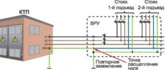
Solid grounding of power transformers to ground
Everything connected to the 0.4 kV distribution network is a neutral with solid grounding to the ground. The presented type has a special place and role in terms of safety. When a short circuit to ground occurs, protection is triggered, in particular, PN-2 burns out or the machine turns off. In relation to such a network, protection is also being developed for wiring in houses and apartments. A striking example is the operation of an RCD, which provides detection of leakage currents.
The main advantages of this type of neutral are:
- Ideal for distributing electrical energy, ensuring the functionality of household and specialized single-phase/three-phase equipment.
- The protection scheme does not require specialized and expensive equipment. Technical means such as fuses or circuit breakers can easily cope with solid ground faults.
Disadvantages include:
- The protections are insensitive to long-range short circuits. It is necessary to accurately calculate the ohmic resistance of the phase-zero loop and the correct choice of circuit breakers or fuses.
- Triggering does not occur if there is no ground fault. This poses a danger to humans, which is corrected through the use of insulated wires.
Three-phase networks with effectively grounded neutrals
In networks of 110 kV and above, the determining factor in the choice of neutral grounding method is the cost of insulation. Here, effective neutral grounding is used, in which during single-phase faults the voltage on the undamaged phases relative to the ground is approximately 0.8 phase-to-phase voltage in normal operation. This is the main advantage of this method of neutral grounding.
Fig.6. Three-phase network with effectively grounded neutral
However, the neutral mode under consideration also has a number of disadvantages. Thus, when one phase is short-circuited to ground, a short-circuited circuit is formed through the ground and the neutral of a source with low resistance, to which the phase EMF is applied (Fig. 6). A short circuit mode occurs, accompanied by the flow of large currents. To avoid equipment damage, prolonged flow of high currents is unacceptable, therefore short circuits are quickly switched off by relay protection. True, a significant part of single-phase faults in electrical networks with voltages of 110 kV and higher are self-repairing, i.e. disappearing after the tension is removed. In such cases, automatic reclosing devices (ARDs) are effective, which, acting after the operation of relay protection devices, restore power to consumers in a minimum time.
The second disadvantage is the significant increase in the cost of the grounding loop installed in switchgears, which must divert large short-circuit currents to the ground and therefore in this case represents a complex engineering structure.
The third drawback is the significant single-phase short-circuit current, which, with a large number of grounded neutrals of transformers, as well as in networks with autotransformers, can exceed the three-phase short-circuit currents. To reduce single-phase short circuit currents, if possible and effective, partial ungrounding of the neutrals is used (mainly in 110-220 kV networks). It is possible to use current-limiting resistances connected to the neutrals of transformers for the same purposes.
General overview
You may be interested in: LED curtains: review, manufacturers, types and reviews
The neutral modes of electrical installations are selected from generally accepted, established world practice. Some changes and adjustments are made due to the characteristics of state energy systems, which is associated with the financial capabilities of the associations, the length of the network and other parameters.
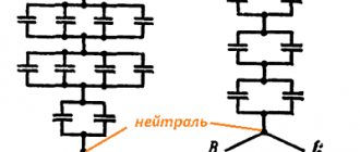
To determine the neutral and its mode of operation, it is enough to navigate the visual diagrams of electrical installations. It is necessary to pay special attention to power transformers and their windings. The latter can be performed with a star or triangle. More details below.
The triangle assumes the isolation of the zero point. Star - the presence of a ground electrode that is connected to:
- ground loop;
- resistor;
- arc suppression reactor.
Networks with solidly grounded neutrals
Such networks are used for voltages up to 1 kV for simultaneous power supply of three-phase and single-phase loads connected to phase voltages (Fig. 7). In them, the neutral of the transformer or generator is connected to the grounding device directly or through a low resistance (for example, through a current transformer). To fix the phase voltage in the presence of single-phase loads, a neutral conductor is used, connected to the neutral of the transformer (generator). This conductor also serves to perform the grounding function, i.e. metal parts of electrical installations that are not normally energized are deliberately connected to it.
If there is a ground fault, an insulation breakdown on the housing will cause a single-phase short circuit and tripping of the protection, disconnecting the installation from the network. If the housing is not grounded (second motor in Fig. 7), damage to the insulation will cause a dangerous potential on the housing. The integrity of the neutral conductor must be monitored, since its accidental rupture can cause voltage imbalance across phases (a decrease in the loaded phases and an increase in the unloaded ones). If necessary, separate execution of the neutral protective and neutral working conductors can be adopted.
Fig.7. Three-phase network with solidly grounded neutral
Classification of premises
According to IEC 60364-7-710.2001, depending on the type of medical procedures performed in the premises, the following classification of premises is provided:
- Gr 0 - med. rooms where electrical appliances are not used;
- Gr 1 - med. rooms where devices are used externally or internally, but a power failure cannot lead to death or serious damage to the life of the patient;
- Gr 2 - premises where a primary fault in the power supply circuit should not lead to failure of life support equipment.
Group 2 rooms include: operating rooms, intensive care rooms, anesthesia rooms, preoperative preparation rooms, postoperative recovery rooms, artificial heart rooms and rooms with children born prematurely.
To power electrical appliances in the premises of medical institutions, Group 2, in order to ensure maximum electrical safety, the use of isolation transformers with a network insulation monitoring system (isolated neutral mode or IT network) is prescribed.
Ensuring uninterrupted power supply
Due to the exceptional importance of the stable functioning of electrical equipment in medical institutions, power supply to the electrical network is provided according to category 1. The presence of two independent power sources is a prerequisite. However, man-made accidents that have become more frequent recently often lead to blackouts of entire areas of the city, and for the reliability of power supply, diesel stations with an automatic start system and uninterruptible power supplies are used as a third power source.
According to IEC 60364-7-710.2001, depending on the type of work for rooms of groups 1 × 2, different durations of switching time and operation of the backup power source are established:
- The switching time is less than 0.5 seconds for lighting operating tables and other necessary lighting equipment, ensuring uninterrupted power supply in the event of a complete failure on two inputs for a period of at least 3 hours.
- Switching time less than 15 seconds for emergency lighting, group 2 medical equipment, medical gas supply equipment, fire alarm.
- Switching time of more than 15 seconds for equipment supporting hospital services (sterilizers, refrigeration, kitchen equipment, etc.).
If the ATS at the network power input does not satisfy the switching time condition (less than 0.5 seconds), it is possible to locally use uninterruptible power supplies for some of the loads.
The uninterruptible power supply is installed before the isolation transformer.