Content
- 1 Description 1.1 Valve type sensing protection
- 1.2 ZDZ with membrane switch
- 1.3 Photothyristor-type ZDZ
- 1.4 Fiber optic type remote control
To protect switchgear cells from the effects of arc faults, protection against arc faults (AFC)
.
Dugov
called a short circuit, accompanied by the occurrence of an electric arc at the point of closure. The most favorable conditions for the occurrence of arc faults are the conditions of closed spaces, therefore almost all short circuits inside switchgear cells are arc faults.
Arc faults in switchgear cells are dangerous because even with a relatively short duration of 0.3-0.5 s, the cell in which the arc fault occurred burns out completely and cannot be repaired. There are often cases when an arc short circuit on busbars that was not eliminated in time led to the burnout of entire sections of switchgear.
ZDZ is based on the physical processes accompanying arc fault:
- an increase in air pressure in a limited compartment of the switchgear cell, due to its expansion under the influence of the thermal energy of the electric arc;
- a bright flash of light from an electric arc.
Arc protection. Types and work. Application and features
Complete switchgears (SGD) up to 35 kV are the most common elements of electrical substations, the advantage of which is their compact size, convenient installation and configuration. If a short circuit occurs inside these devices, the power outage time should not exceed 1 second. This is due to their small size. This problem is complicated by the fact that switchgear manufactured in the last century most often did not have arc protection installed.
Fiber optic type remote control[edit]
Like the photothyristor type PDZ, this type of PDZ reacts to a light flash from an electric arc. A fiber-optic sensor (FOS) is used as a sensor that reacts to a light flash from an electric arc. FOS are placed one in each compartment of the switchgear cell:
- in the input compartment;
- in the withdrawable element compartment;
- in the cable compartment.
During an arc short circuit, each FOD detects a light flash from the electric arc and generates a “Trigger” signal, which is transmitted via fiber-optic communication line to the MP terminal ZDZ. In turn, the MP terminal ZDZ, based on the “Trigger” signals from the VOD, generates commands to turn off the corresponding switches in order to eliminate the arc short circuit.
To prevent malfunction of the sensing device, current control is provided - a shutdown signal is issued by the MP terminal of the sensing protection device only in the presence of 2 factors:
- “Trigger” signal from the water supply;
- signal “Start MTZ” from the protection terminal (protection terminal of the switchgear input or protection terminal of the HV side of the transformer).
If there is only a “Trigger” signal from the VOD without a “Start MTZ” signal, the switches from the RDZ are not disconnected and the MP terminal of the RDZ issues the signal “VOD Failure”.
- Pneumatic membrane switch 8 AX 10
Arc protection
Arc protection is also called arc fault protection (AFP). Recently, optical arc protection, abbreviated as (ODP), has been increasingly used. It is a type of short circuit protection, the principle of which is based on triggering when an arc flash occurs.
The most common are phase-to-phase faults, as well as ground faults.
These dangerous phenomena are usually accompanied by:
- Release of a significant amount of heat.
- Current surges.
- Voltage impulses.
- Transition processes.
Trigger conditions:
- Increasing current . When an arc occurs, a short circuit usually occurs. This condition is called current control.
- Sensor activation . Nowadays valve arc protection is often used. At the moment of closure, excess pressure builds up, as a result of which the metal lid that covers the high-voltage cell flies out and closes the valve contact. The closure of this contact and the presence of current control creates the conditions for the protection to operate.
- Recently, many substations have used modern optical arc protection. Here the sensors are no longer valves, but fiber-optic sensors that respond to a flash of light .
Causes of arc faults:
- Aging or damaged insulation.
- Violation of the connection diagram of cables and buses.
- Electrical fault.
- High humidity.
- Pollution.
- Corrosion.
- Increased tension.
- Maintenance personnel errors.
These causes can be prevented by good maintenance. Time is of the essence when identifying and mitigating the effects of arc faults. An arc lasting 0.5 seconds can severely damage the insulation, causing the switchgear cell to burn out completely.
Processes during closure
These processes depend on the time of exposure to the current and its magnitude. Short circuit current is characterized by a significant increase in temperature. The degree of damage depends on the wear rate of the equipment and the quality of the insulation.
When an arc fault occurs, the metal walls of the cell are burned through, and the fault can spread to neighboring cells. Also, with good tightness of modern equipment and the absence of safety valves, high pressure during closure destroys the equipment and the cell body, which contributes to the complete destruction of all elements of the cell.
The consequences of an arc fault in switchgear can be very serious. In this case, expensive equipment is damaged, resulting in downtime and the enterprise incurring economic losses. Also, the consequences may be injuries to operating personnel.
How does arc protection work?
The sensor of this protection is a device that reacts to an electric arc flash and transmits information to actuators that turn off the electricity to prevent negative consequences.
Arc detection methods:
- Determination of the change in brightness of light caused by an electric arc.
- Comparison of the characteristics of the electrical circuit before and after the circuit.
- Comparison of pressure and temperature in the chamber of the switchgear before and after the circuit.
Bus fault protection
Organized in switchgears from 6 to 10 kilovolts to protect busbars, for devices with closed current-carrying elements.
Protection works in two ways:
Fiber Optic Protection
Its operation is based on the principle of detecting an electric arc flash using special optical sensors. Such protections are placed in the input compartments, on the withdrawable element of the cells, in the cable compartments. Electric arc detection is carried out immediately in all protection elements.
Cells are de-energized under the following conditions:
Sensor types
- Distribution ones, covering several flash detection locations with one cable.
- With fastening at the end part, they make it possible to accurately detect the presence of an arc.
Advantages
- Immunity to electromagnetic interference.
- The use of insulating materials in sensor devices.
- High performance.
- Low cost of equipment, installation and configuration.
Photothyristor arc protection
Photothyristors are used as a sensitive element, responding to changes in light brightness.
Valve protection
The operation of this system is to use the processes that occur during an arc fault: increasing the pressure in the chamber. As a sensitive element, this arc protection includes special valves with switches that are installed in the switchgear chambers.
Membrane protection
The principle of operation is the ability of a membrane-type switch to respond to changes in air pressure from an electric arc. The components of this protection are membrane sensors, back pressure valves, and flexible pipelines.
Scope of application of photothyristors
The main purpose of a photothyristor is to create switching devices controlled by a light beam. Powerful TFs with direct control of the luminous flux compete with other power semiconductor devices. They are used to solve the most complex problems in the power industry:
- In energy-saving converters used in DC networks.
- As high-voltage pulse switches that are capable of controlling ultra-high powers in ultra-short time intervals. Such keys can be used in equipment that powers high-power laser technology.
- In reactive power compensators.
In low-voltage, low-power converters, photothyristors are used for direct load switching. In high-power converters, typically used in high-voltage networks, a low-power photothyristor drives a powerful power triac that turns on the load.
Types of photothyristor designs
This type of thyristor has a structure with three or more pn junctions. Without external influence, the photothyristor is in a locked state. In this case, an insignificant dark current flows through it. There are two options for opening potential barriers and putting the device into operation:
- Light flux.
The design of the photothyristor has a window with protective glass and a focusing lens on one side of the housing. Through the window, light enters the surface of the semiconductor structure. An element of self-protection of the device from breakdown when the voltage increases above a critical level is integrated into the housing. - By applying voltage to the control electrode.
The control output in this semiconductor device is an optical input with an optical interface cable connected to it. The kit includes a laser diode that converts the electrical signal from the control driver into a light pulse arriving at the semiconductor structure.
Valve arc fault sensor
A valve arc fault sensor is a device that provides pressure reduction in the distribution device cell[1].
The valve arc fault sensor responds to an increase in gas pressure that occurs when an arc occurs that accompanies a short circuit. As is known, when an arc flash occurs with short circuit currents of more than 20 kA, the metal of the cell walls can be burned and damage to neighboring cells can occur.
Increasing the thermal resistance of a cell by thickening its walls (according to some data, increasing thermal resistance by 1.5 times will require increasing the wall thickness by 2 times) leads to an increase in price, weight and complicates the installation of cells.
According to some experts, during intense arc combustion, accompanied by the release of a large amount of hydrogen, the formation of an explosive mixture (H2 + O2) is possible, which can lead to an explosion in adjacent, undamaged cells.
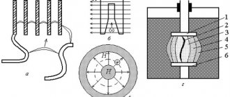
The valve sensor, by reducing the pressure inside the cell, prevents destruction of the structural elements of the cell. The location of the sensor is chosen so as to prevent the release of arc combustion products into the service corridor (Fig. 1)
Fig. 1 Location of the valve sensor in the KRU38-12 cell of the switchgear:
1 – valve sensor, A – relay compartment, B – drawer element (switch) compartment, C – busbar compartment, D – current transformer and linear busbar compartment
A valve sensor equipped with a limit switch generates a signal that can be used for various purposes, including to turn off the switching device.
The disadvantages of traditional sensors of this type are large sizes, low speed, the possibility of false alarms, and a high response threshold (the arc fault current must be more than 5 kA).
Many of the disadvantages of traditional sensors of this type are eliminated in the “Crab” valve sensor (Fig. 2)
Rice. 2 Valve sensor “Crab” (according to [1])
1 - housing, 2 - cable, 3 - limit switch, 4 - drive lever
The special design of the valve (RF patent No. 1686559) made it possible to reduce the inherent response time of the “Crab” sensor to 0.015-0.020 s. However, the overall arc protection trip time with any valve sensor mainly depends on the trip time of the limit switch.
Currently, arc protection valve sensors are used together with sensors that use other methods of recognizing arc short circuits and monitoring:
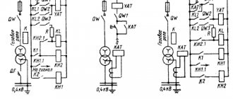
Operating principle of arc protection
To prevent burnout of the cells of complete switchgears, modern circuits are equipped with electric arc protective relays, which remove the switches from the operating position when damage is detected in the cell. Arc protection of switchgear operates much faster and more efficiently than traditional maximum current protection (MCP), which protects power equipment by increasing the current in the circuit when a short circuit is detected.
The principle of the protective action of the relay is based on the recognition of an electric arc flash by the sensor and the transmission of information to the actuators, which are triggered by a power outage in the switchgear to prevent negative situations. The appearance of an arc causes a change in parameters: light brightness, characteristics in the circuit, pressure and temperature.
To prevent short circuits from spreading to other switchgear cells, complete shutdown of equipment is provided, including arc protection of busbars (low-resistance electrical conductors).
Advantages of photothyristors
These semiconductor devices provide:
- direct control of light pulses;
- high efficiency;
- characteristics optimized for serial connection of devices in combined assemblies;
- resistance to prolonged and repeated current overloads;
- switching on groups of devices with high time accuracy;
- resistance to electromagnetic interference;
- the presence of galvanic isolation between the control and power circuits;
- no need for frequent maintenance activities;
- simplicity and safety of operation.
Arc and logical busbar protection
Arc protection is a special type of high-speed protection against short circuits, based on recording the light spectrum of an open electric arc.
A significant danger for complete switchgear (SGD) with a voltage of 6-10 kV is posed by internal short circuits (SC), accompanied by an electric arc (EA). The temperature of the electric arc can reach values of the order of 7000 ... 12000 °C in less than one period of industrial frequency.
Source
Danger of sparks in switches, wires and twists
Almost every person is familiar with sparking and arc breakdown. If you press the light switch button in the dark, then with some probability you will be able to see a dim, short-term green flash through the plastic case. This effect is more typical of old switches.
The phenomenon is of a completely logical nature. When the light is turned on, the switch contacts move closer. At some point in time they are so close that a breakdown of the air gap occurs between them. A very small and short-lived arc lights up, which creates a flash.
This situation is safe if we talk about a working switch. However, this often happens in junction boxes. If the wires are loosely twisted or poorly pressed under the terminal block of the machine, they will also spark. At the same time, the voltage and current in the network behave in the most unpredictable way. The problem is aggravated by the presence of capacitive and inductive consumers in the apartment.
Important! Poor contact in the twist, box or under the terminal block of the circuit breaker leads to sparking of the wiring. This, in turn, creates involuntary surges in mains voltage and current
This phenomenon can damage expensive household appliances. Especially those that contain electronic chips, processors and digital circuit boards.
Poor contact in twist