An example of calculating the current of a single-phase short circuit
In this article, I will consider an example of calculating the current of a single-phase short-circuit (SC) using in the first version the reference tables presented in [L1], and in the second version the reference tables from [L2].
Methods for determining the magnitude of a single-phase short-circuit current and the reference tables provided for all elements of a short-circuited circuit can be found in the article: “Calculation of single-phase short-circuit currents when powered from the power system.”
Initial data:
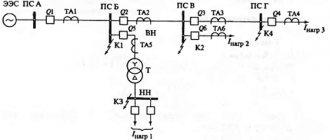
- oil transformer with voltage 6/0.4 kV, power 1000 kVA with winding connection diagram - Y/Yо.
- From the transformer to the ASU, a AAShvU 3x95 cable with a length of 120 m is used.
- From the ASU to the engine, a AASHvU 3x95+1x35 cable with a length of 150 m is used.
Fig. 1 - Design diagram of the electrical network. engine
Option I
1. Calculation of the single-phase short circuit current will be performed using the formula of the approximate method at high power of the supply power system (Xc < 0.1Хт) [L1, p. 4 and L2, p. 39]:
Where:
- Uph – phase voltage of the network, V;
- Zt – total resistance of the transformer to the current of a single-phase short circuit to the body, Ohm;
- Zpt – total resistance of the phase-zero loop from the transformer to the short-circuit point, Ohm.
2. Using Table 2 [L1, p. 6], we determine the resistance of the transformer at a secondary voltage of 400/230 V, Zt/3 = 0.027 Ohm.
3. We determine the total resistance of the phase-zero circuit for the section from the pipeline to the short-circuit point using formula 2-27 [L2, p. 40]:
Where:
- Zpt.ud.1 = 0.729 Ohm/km – total resistivity of the phase-zero loop for cable brand AAShvU 3x95, determined according to Table 12 [L1, p. 16];
- l1 = 0.120 km – length of section No. 1.
- Zpt.ud.2 = 0.661 Ohm/km – total resistivity of the phase-zero loop for cable brand ААШвУ 3х95+1х35, determined according to Table 13 [L1, p. 16];
- l2 = 0.150 km – length of section No. 2.
4. Determine the single-phase short circuit current:
I draw your attention to the fact that when determining the magnitude of the single-phase short-circuit current using the approximate method, the contact resistances of busbars, devices, and current transformers are not taken into account in this method, since the arithmetic sum of Zt/3 and Zpt creates a certain reserve [L2, p. 40].
Option II
Let's determine the single-phase short circuit current using the reference tables from [L2].
1. Using Table 2.4 [L2, p. 29], we determine the transformer resistance Zt/3 = 33.6 mOhm.
2. We determine the total resistance of the phase-zero circuit for the section from the pipeline to the short-circuit point using formula 2-27 [L2, p. 40]:
Where:
- Zpt.ud.1 = 0.83 mOhm/m – total resistivity of the phase-zero loop for cable brand AAShvU 3x95, determined according to Table 2.11 [L2, p. 41];
- l1 = 120 m – length of section No. 1.
- Zpt.ud.2 = 1.45 mOhm/m – total resistivity of the phase-zero loop for cable brand AAShvU 3x95+1x35, determined according to Table 2.10 [L2, p. 41].
Please note that in this table the value of Zpt.ud. given for cables regardless of the cable sheath material. If you look at [L1, p. 16], then in table 13 for 4-core cables with an aluminum sheath 3x95+1x35, Zpt.ud. = 0.661 mOhm/m. I accept Zpt.ud.2 = 1.45 mOhm/m, in order to clearly see how much the value of the single-phase short-circuit current will differ from the calculation according to “Option I”. In practice, it is better to combine lookup tables from [L1 and L2].
3. Determine the single-phase short circuit current:
As can be seen from the calculation results (option I: Ik = 1028 A; option II: Ik = 627 A), the obtained values of the single-phase short-circuit current are almost 2 times different. Decide for yourself which reference tables to use to calculate the single-phase short-circuit current; in any case, this is an approximate method, therefore, if you need exact values of the single-phase short-circuit current, you should calculate using the formula presented in GOST 28249-93.
Literature:
1. Recommendations for calculating the resistance of the phase-zero circuit. Glavelektromontazh. 1986 2. Belyaev A.V. Selection of equipment, protection and cables in a 0.4 kV network. Tutorial. 2008
All the best! See you again on the Raschet.info website.
power transformers
Active and inductive resistance of positive sequence of step-down transformers ( r
t,
x
t) in milliohms, reduced to the lowest voltage stage of the network, are calculated using the formulas:
(3)
(4)
where is the rated power of the transformer, kV×A; – short circuit losses in the transformer, kW; – rated voltage of the low voltage winding of the transformer, kV; And
k – short circuit voltage of the transformer, %.
Active and inductive zero-sequence resistances of step-down transformers, the windings of which are connected according to the D/ Y
0, when calculating a short circuit in a low voltage network, it should be taken equal to the active and inductive positive sequence resistances, respectively. For other connection schemes of transformer windings, active and inductive zero-sequence resistances must be taken in accordance with the manufacturers' instructions.
An example of an approximate calculation of short circuit currents in a 0.4 kV network
Often, to check the breaking capacity of protective devices (circuit breakers, fuses, etc.), engineers need to know the values of short circuit currents (SCC). But in practice, it is not always possible to quickly calculate TKZ in accordance with GOST 28249-93, due to the lack of data on various resistances, this is especially true when calculating single-phase short circuit current to ground.
To solve this problem, you can use the approximate method for calculating short-circuit currents for voltages up to 1000 V, presented in the book: “E.N. Zimin. Protection of asynchronous motors up to 500 V. 1967.”
Let us consider, as an example, the calculation of TKZ in a 0.4 kV network for a small distribution point in order to check the breaking capacity of fuses, using the approximate method of calculating TKZ presented in the book by E.N. Zimina.
Please note that in this example, only the calculation of TKZ for fuses FU1-FU6 will be considered from the condition of ensuring the required short circuit current ratio.
Calculation
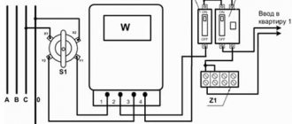
It is known that the engines are powered by a transformer with a power of 320 kVA. The cable from the transformer to RShch1 is laid in the ground, brand ASBG 3x120+1x70, line length is 250 m. In the section from the switchboard ShchR1 to the distribution point RP, a cable of brand AVVG 3x25+1x16 is laid, line length is 50 m. A single-line electrical diagram is presented in Fig. 1.
Fig. 1 – Single-line electrical diagram 380 V
Calculation of short-circuit currents for point K1
To check the breaking capacity of fuse FU1, it is necessary to determine the three-phase short circuit current at the place of its installation.
1. Determine the active and inductive resistance of the transformer phase:
Where:
- St – transformer power, kVA;
- c – coefficient equal to: 4 – for transformers up to 60 kVA; 3.5 – up to 180 kVA; 2.5 – up to 1000 kVA; 2.2 – up to 1800 kVA;
- d – coefficient equal to: 2 – for transformers up to 180 kVA; 3 – up to 1000 kVA; 4 – up to 1800 kVA;
- k = Un/380, Un — rated voltage on the distribution point buses.
2. Determine the active and inductive resistance of the ASBG 3x120+1x70 cable:
Where:
- L – section length, km;
- Sф and S0 – cross-section of the phase conductor and, accordingly, the neutral wire, mm2;
- a – coefficient equal to: 0.07 – for cables; 0.09 – for wires laid in a pipe; 0.25 – for insulated wires laid openly;
- b – coefficient equal to: 19 – for copper wires and cables; 32 – for aluminum wires and cables;
3. Determine the phase impedance:
4. Determine the three-phase short circuit current:
To check the breaking capacity of fuses FU2 - FU6, you need to determine the single-phase short circuit current to ground at the end of the protected line.
Calculation of short-circuit currents for point K2
5. Determine the total active and inductive resistance of the cables in the short circuit:
6. Determine the total resistance of the phase-zero loop:
where: Zt(1) = 22/St*k2 – calculated total resistance of the transformer to ground short circuit current, k=Un/380.
7. Determine the current of a single-phase short circuit to ground:
We similarly carry out the calculation of the TKZ for points K3-K6, the calculation results are entered into Table 1. Knowing the short-circuit currents, you can now select fuse links for fuses FU1 - FU6, based on the condition of ensuring the required short-circuit current ratio.
Table 1 – Calculation of short-circuit currents
| Short circuit point | Rph, Ohm | R0, Ohm | Hf, Ohm | X0, Ohm | RT, Ohm | Ht, Ohm | Zph-0, Ohm | Zt, Ohm | Ic.c.(3), A | Ic.c.(1), A |
| K1 | 0,07 | 0,02 | — | — | 0,0078 | 0,023 | — | 0,089 | 2468 | — |
| K2 | 0,241 | 0,374 | 0,022 | 0,022 | — | — | 0,674 | — | — | 326 |
| K3 | 0,374 | 0,598 | 0,0231 | 0,0231 | — | — | 0,99 | — | — | 222 |
| K4 | 0,174 | 0,278 | 0,022 | 0,022 | — | — | 0,512 | — | — | 429 |
| K5 | 0,694 | 1,11 | 0,0259 | 0,0259 | — | — | 1,8 | — | — | 122 |
| K6 | 0,174 | 0,278 | 0,022 | 0,022 | — | — | 0,512 | — | — | 429 |
All the best! See you again on the Raschet.info website.