- home
- Relay protection
- Calculation of relay protection of a 10 kV line
A power transmission line transports electricity from point A to point B. At a voltage of 6-35 kV, power lines are made with a compensated or isolated neutral.
This circumstance imposes certain features of the implementation of relay protection devices. For example, in these networks, long-term (up to several hours) operation with a single-phase ground fault (SGF) is acceptable. In this case, the load is transferred to another line, after which a shutdown occurs. There are also options when protection from ground faults only affects the signal, or is absent altogether.
Protection against two-phase and three-phase short circuits is ensured by installing relay protection and automation kits in two phases out of three: phase A and phase C. Since a single-phase short circuit is not critical, in case of a two-phase or three-phase short circuit the entire line will always be disconnected.
- f.A+B
=> switches off via f.A line - f.A+C
=> switches off in two phases - f.B+C
=> f.C line will be disconnected
It's another matter if a double ground fault occurs. This is when two parallel lines are closed in one opposite phase. As a result, we have a total of 6 short circuit options:
- in 2 cases one line is disconnected
- in 2 cases another line
- and in 2 more cases 2 lines are disconnected at once
It turns out that in 4 out of 6 options one of the lines remains in operation. This is an advantage of this connection method. It’s another matter if, when the phases are separated, they suddenly put A and B, or B and C in the wrong place. Then the options will become worse and the likelihood of accidents will increase.
A modest example, we measured the current on a section, or on some kind of engine, through the terminal block in the relay compartment. And after starting up and increasing the load, we discovered that what we were displaying was real nonsense. As a result, it turned out that phase B and zero from the CT were swapped. As they say, a defect has been identified that needs to be fixed. This is why there is adjustment, so that after installation, you can check the readiness and put it into operation for trouble-free operation.
Tricky question? Why is a double short circuit to the same phase not considered a double ground fault?
Now let's move on to the consideration and quick calculation of the following protections: MTZ, TO, OZZ. Runaway, since there are so many nuances that people have written dozens of books on this topic. Protection can be performed either separately on a relay or in a complex, as part of a microprocessor terminal. To protect the line, three-stage current protection can be used, where:
- 1st stage (instantaneous current cut-off) 3I>>>
- 2nd stage (with time delay) 3I>>
- 3rd stage (MTZ) 3I>
The TO has the highest current setting - this is rough protection, while the MTZ is more flexible and allows you to perform long-range backup functions.
MTZ lines 6-35 kV
I have already considered MTZ, but repetition is the mother of learning. Time-delay overcurrent protection acts as the first stage of three-stage line protection. To make the calculation, it is necessary to calculate the protection operation current, setting current, time delay and differentiate from neighboring protections.
1) At the first stage, we determine the protection operation current, taking into account self-starting currents and other overcurrents that flow during the elimination of a short circuit on the previous element:
in this formula we have the following components:
Is.z.
— current of protection 2РЗ, the value that we determine
kn
— reliability factor, which in fact can be considered rather as a detuning factor for increasing the set value; for microprocessor ones it is 1.05-1.1, for electromechanical ones it is 1.1-1.4.
kszp
— self-starting coefficient, its meaning is that during a short circuit the voltage drops and the motors self-start. If there are no 6(10) kV motors, then the coefficient is assumed to be 1.1-1.3. If there is a load, then the calculation is made under the condition of self-start of the electric motor from a completely inhibited state. The self-starting coefficient is defined as the ratio of the calculated self-starting current to the maximum operating current. That is, knowing the self-starting current, you may not know the maximum operating current, although without this knowledge it will not be possible to calculate the self-starting current - in general, it will not be possible to shorten the formula much.
kv
— return coefficient of maximum current relays; for digital - 0.96, for mechanics - 0.65-0.9 (depending on the type of relay)
Iwork.max.
— the maximum operating current, taking into account possible overloads, can be obtained from dispatchers, if you have a telephone number and authority. For transformers up to 630 kVA = 1.6-1.8*Inom, for transformers of two-transformer substations 110kV = 1.4-1.6*Inom.
2) At the second stage, we determine the protection operation current, coordinating the protections L1 and L2:
Is.s.s.s.
— tripping current of protection 2РЗ
kn.s.
— coordination reliability coefficient, the value of this coefficient is from 1.1 to 1.4. For relay RT-40 - 1.1, for RTV - 1.3...1.4.
kр
— current distribution coefficient, with one power source, is equal to unity. If there are several sources, then it is calculated through equivalent circuits and element resistances.
First sum in brackets
- this is the largest of the geometric sums of the overcurrent protection currents of parallel operating previous elements.
The second sum
is the geometric sum of the maximum values of the operating currents of the previous elements, except for those with which coordination occurs.
3) At the third stage, we select the largest of the currents determined by conditions 1) and 2) and calculate the current setting:
kсх
- circuit coefficient, this coefficient shows how many times the current in the relay is greater than the current I2 of the current transformer in symmetrical normal operation; when switched on to phase currents (star or open star) it is equal to 1, when switched on to the phase current difference (triangle) it is 1.73.
nt
— transformation ratio of the current transformer.
4) Next, the sensitivity coefficient is determined, which must be greater than or equal to the value specified in the PUE.
The ratio of the minimum current flowing in the relay, under the least favorable operating conditions, to the relay operating current (set). For MTZ, the value of kch must be at least 1.5 for a short-circuit in the main protection zone and at least 1.2 for a short-circuit in distant redundancy zones.
5) Determine the time setting
The meaning of the time settings is as follows: if we have a short circuit as in the figure above, then switch L1 (located closer to the short circuit) must first turn off; this is necessary in order to leave undamaged sections of the system in operation.
That is, tс.2рз=tс.1рз+dt
, where delta t is the selectivity level. This value depends on the speed of the protection (in particular, the accuracy of the time relay) and the on-off time of the switches.
If the previous RP is a current cut-off or the RP is made using electronic (semiconductor) relays, dt can be taken as 0.3 s. If electromechanical relays are used in the relay protection, then dt can be 0.5...1.0. For different relays this value can reach several seconds.
As was written above, a feature of MTZ is the accumulation of time delays from element to element. And the larger the dt value, the larger the remote setpoint will be. To solve this problem, digital relays (dt=0.15...0.2s) and identical switches should be installed. After all, if the switches are of the same type, then the response time is the same for all. And if it is small, then the total value will be small.
In general, the choice of MTZ consists of three stages:
- failure of 2RZ during overcurrents in post-emergency modes
- coordination of 2РЗ with 1РЗ
- ensuring sensitivity during short circuit at the end of L1 (working zone) and at the end of L2 (long-range backup zone)
Calculation of maximum current protection
Current protections are divided into current cutoffs (TO) and maximum current protections (MCP). MTZ and TO are the simplest and most frequently used in medium and high voltage electrical networks.
Operating principle of current protection (TC)
is based on disconnecting a section of the network in which the current value exceeds a specified value (current operation setting).
Selective operation of the MTZ is ensured by adjusting the protection stages over time. For dead-end lines, as a rule, lines up to 10 kV, overcurrent protection and maintenance serve as the main protection. In networks with more complex configurations, TK are only backup.
This is explained by the difficulty of ensuring selective operation of the overcurrent protection system for areas with double-sided power supply. In this case, more complex directional protections are used.
The operation of MTZ is characterized by two parameters: current and response time. When determining the protection operation current Iсз
, the initial criterion is the detuning from the load current, as well as from possible short-term surges in the load current caused by transient processes in the network.
When calculating the overcurrent protection settings, two conditions must be met:
1) The protection should not come into action at load currents, for which the current Iсз must exceed the load current:
Iсз>In.max;
2) The protection must reliably return to its original state after startup, for which the following condition must be met:
Ivot>kзkнIн.max;
where Icart
– relay return current to its original state.
Icart
should be greater than the load current at the first moments after the protection is triggered; its increase after operation is explained by the self-starting of the engines;
kz
– launch coefficient. Defined as the ratio of the starting current of all engines remaining in operation after an emergency shutdown to the maximum operating current;
kn
— reliability coefficient. Takes into account the error of the relay return current and is assumed to be 1.1–1.2;
Return current ratio Ireturn
to the protection operation current
Iсз
there is a return coefficient
kvoz
.
Finally, the overcurrent protection current is determined from the condition:
Iсз>(kзkнIн.max)/kvoz;
Calculation of MTZ
.
When calculating settings, it is necessary to realistically evaluate the possible value of In.max
.
The value of In.max
is checked during power surges as a result of disconnection of one of two parallel lines, as a result of the operation of an automatic transfer switch on the switchgear buses.
It should be taken into account that heavy duty operation also occurs during automatic reclosure of disconnected sections, when self-starting of the IM occurs.
Selected according to the condition of detuning from the load current Iсз
, is checked according to the protection sensitivity condition, which is characterized by the sensitivity coefficient:
kch=Ik.min/Isz;
where Ik.min
– minimum short circuit current (SC). As a rule, the current is a single-phase earth fault at the end of the protected section. The protected area for overcurrent protection is the line adjacent to the buses where the relay protection and automation device is installed, and the next area behind the buses of the receiving substation.
kch
on the main site it must be at least 1.5; for the reserved area no less than 1.2.
The second, no less important parameter of the MTZ operation is the response time tз
. From the condition of selectivity of operation of the TC in adjacent sections, the response time of the head section A should be greater than the response time of the subsequent section B.
The difference in the response time of the protections of these sections is called the response time stage or selectivity stage Δt
.
Value Δt
depends on the time of operation of the switch, the delay time of the protection of the adjacent area and the error in the direction of slowing down the operation of the relay.
For MTZ with independent time delay, Δt
is determined by the expression:
Δt=tп(в)+tв(в)+tп(а)+tzap;
where tп(в), tп(а)
— errors in the response time of the TC in adjacent sections B and A, respectively;
tв(в)
– time of switching off the circuit breaker from the moment the impulse is applied to switching off until the moment the short-circuit arc breaks in section B;
tzap
– stock time.
For TZ with dependent and limited dependent time delay Δt
determined by the expression:
Δt=tп(в)+tв(в)+tп(а)+tза+ti(а);
where ti(a)
– additional time, taking into account the inertia of induction relays.
For overcurrent protection with an independent shutdown characteristic, the response time is determined:
tз(а)=tз(в)+Δt;
For protections with dependent and limited-dependent characteristics, the condition for selecting the response time is similar to the above condition, however, the selectivity level has a certain range.
This is explained by the fact that the response time of induction relays is ambiguous and depends on the magnitude of the short-circuit current. Coordination of dependent characteristics of technical specifications is carried out in the following order:
a) construct the characteristic t=f(I)
protection B, with which the characteristics of protection A will be coordinated;
b) find the maximum value of the short-circuit current. at the beginning of protection section B, which will pass through both adjacent sections;
c) according to the schedule t=f(I)
protection B, find the response time of protection B at maximum short-circuit current (see previous paragraph);
d) determine the response time of protection A according to the condition:
tз(а)≥tз(в)+Δt;
e) build protection characteristic A together with protection characteristic B. Selectivity is assessed over the entire period of their joint operation.
MTZ is most widely used in radial networks. The advantage of technical specification is its simplicity and low cost.
Disadvantages include a relatively long shutdown time near power centers and low sensitivity in networks with a complex configuration with many parallel connections.
Calculation of line current cutoff
Maintenance can be performed both with a time delay (current cut-off with slowdown) and without it. When calculating the TO, it is adjusted from the maximum short circuit current at the end of the protected line. The transformer's maintenance is also adjusted against the inrush of the magnetizing current. Formulas and more details about current cutoff are written here.
To prevent the effects of overcurrents and short circuits that cannot be switched off with a time delay, non-selective maintenance without a time delay
. This is applicable to protect synchronous machines from short circuits on the buses, which can lead to disruption of the stability of parallel operation of the TG with the power system and disruption of the power supply. Formula for determining the response current of non-selective maintenance:
In the above formula:
Uс.min
— phase-to-phase voltage of the system in minimum operating mode (0.9...0.95), V
kn
— already familiar reliability factor = 1.1…1.2
zs.min
— system resistance to the location where the cutoff is installed, Ohm
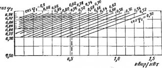
ko
— coefficient of dependence of the residual voltage at the location of the cutoff installation on the distance of the 3ph short circuit, determined by the dependence of the graphic
Residual voltage is the voltage at which the dynamic stability of synchronous generators (Ures>0.6) and electric motors (Ures>0.5) is ensured.
This non-selective maintenance is used in conjunction with automation (AVR, Automatic Automatic Recloser), which ensures fast response when disconnecting dangerous short circuits. However, for collaboration it is necessary to perform a number of activities:
- rebuild the maintenance from the magnetizing currents of transformers,
- repair fault repair on the LV busbars of transformers located in its coverage area
- coordinate maintenance with fuses, switches and other devices located within its coverage area
Single-phase earth fault protection
When calculating protection against short circuit protection, you should know the method of grounding the neutral and, depending on this, carry out further actions. In 6-35 kV networks, zero-sequence current protection is used. The conditions for its selection are to determine the protection operation current and determine the sensitivity coefficient
In this formula
Ic.feed.max
— feeder’s own capacitive current
kn
— reliability coefficient equal to 1.2
kbr
— coefficient of capacitive current inrush when a short-circuit fault occurs
Iс.sum
- the total capacitive current of the network, which can be determined using the formulas below:
for isolated neutral:
Operation in a network with an isolated neutral is allowed if the capacitive current does not exceed:
- 30A for 6kV network
- 20A for 10kV network
If the value of the capacitive current exceeds the obtained value, then it is necessary to compensate it using a reactor, that is, switch to another type of neutral grounding.
Current data can also be obtained from specialized organizations. Or determine experimentally what gives the most accurate and realistic value.
Calculation of settings and checking the sensitivity of overcurrent protection in a network with one-sided power supply. Selection of protection schemes
Exercise
For MTZ 1 and 2 in the network shown in Fig. 3.1:
1) determine the operating currents Iсз1 and Iсз2, the operating times tсз1 and tсз2, as well as the operating currents of the current relay Iср1 and Iср2 of these protections,
2) select a circuit for switching on current relays MTZ 1 and 2 and evaluate the sensitivity of MTZ 1 and 2.
Rice. 3.1. Network diagram
In calculations, take the detuning factor kots=1.2; return coefficient kв= 0.9; load motor starting factor kз = 1.5; selectivity level Δt = 0.5 s. The maximum operating currents of loads, three-phase short-circuit currents and response times of MTZ 3-6 are given in table. 3.1. Current transformers (CTs) are selected in accordance with the scale of primary rated currents Inom and transformation ratios KI (Table 3.2).
Guidelines
To point 1). Currents and operation times of overcurrent protection 1 and 2 are selected in accordance with expressions (2.1) - (2.5) given in the guidelines for Exercise 2. After determining the protection operation current, the relay operation current Iср is calculated, the value of which depends on the connection diagram of the secondary windings of the current transformers and its transformation coefficient:
where kсх(3) is the circuit coefficient in symmetrical mode (defined as the ratio of the current in the relay winding to the secondary current of the relay); KI is the transformation ratio of the current transformer (defined as the ratio of the primary rated current Inom to the secondary rated current 5 A). Current transformers for protection should be selected with primary rated currents greater than the corresponding maximum operating CURRENTS (Iwork.maxI and Iwork.max2), i.e.
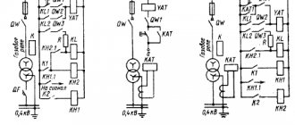
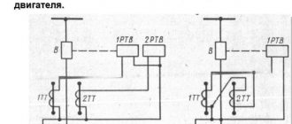
The values of kсх(3) depend on the connection diagram of the TA and the protection current circuits, the implementation options of which are shown in Fig. 3.2.
Rice. 3.2. Options for implementing current protection circuits against phase-to-phase short circuits
To point 2). In networks with Unom≤35 kV, in which there are no single-phase short circuits, it is advisable to protect lines with two TAs (two-phase circuits), usually connected throughout the entire network in the same phases (A and C). In networks with Unom≥110 kV, which operate with solidly grounded neutrals of transformers (autotransformers), for protection it is necessary to have TA in all three phases (three-phase circuits) to ensure their operation even during single-phase short circuits.
In practice, the following current protection schemes are used, shown in Fig. 3.2:
a - partial star (two-phase with two current relays KA1 and KA2);
b - incomplete star (two-phase with three current relays, in which the third current relay KAZ is switched on for the sum of the currents of two phases);
c - full star (three-phase with three current relays);
d - full triangle (three-phase with three current relays);
d - incomplete triangle (two-phase with one current relay).
To implement protection against phase-to-phase short circuits, two-phase circuits are used. In section 2, you should consider the possibility of using a partial triangle scheme (see Fig. 3.2, d), as the simplest. In case of insufficient sensitivity, one should switch to the incomplete star scheme (see Fig. 3.2, a). The sensitivity of protection 2 is estimated by the sensitivity coefficient
where Iр.min is the minimum current flowing in the current relay during a short circuit at the end of the protected section (point K2) and at the end of the reserved section (point K4). The minimum current value Iр.min occurs during a two-phase short circuit, since the following relations take place at the short circuit location.
The minimum current value Iр.min occurs during a two-phase short circuit, since at the short circuit location the following relationship takes place:
In the event of a short circuit at point K2, the sensitivity of protection 2 is checked as the main one:
and at point K4 - as a backup:
According to the PUE [3], it is necessary to have kch.bas≥1.5 and kch.res≥1.2.
If the incomplete triangle circuit for protection 2 does not satisfy the requirements of the PUE, you should switch to the incomplete star circuit (see Fig. 3.2a), the sensitivity coefficients of which during a short circuit at the same points will be √3 times greater. This is due to the fact that for this circuit 1, and therefore, in accordance with expression (3.1), its current Iav will be √3 times less compared to the partial triangle circuit.
For the protection circuit of 1 head section, you should consider a partial star circuit with two relays (see Fig. 3.2a), if its sensitivity is sufficient for a short circuit behind the step-down transformer T (short circuit point), or with three relays (see Fig. 3.2b ) otherwise. A circuit with three current relays for a two-phase short circuit behind a transformer with winding connection Y/Δ-11 is 2 times more sensitive than a circuit with two relays (see Fig. 1.5, exercise 1).
From the vector diagrams in Fig. 1.8 and 1.11 it follows that it is impossible to use a partial triangle circuit for protection 1. As a result of calculating the sensitivity coefficients of protection 1 during a short circuit at point K1 (as the main one) and at points K2 and K2 (as a backup), an acceptable circuit is selected.
Example of calculation of MTZ I and 2 according to option a).
1. Determine Iwork.max 2 and Iwork.max1:
2. Determine the overcurrent protection currents:
3. Determine the response times of the protections:
4. Select according to the table. 3.2 TA for protections 1 and 2 - KI = 100/5.
5. For protection 2, we accept a partial triangle circuit (kсх(3)=√3) and determine the relay operation current:
6. Check the sensitivity of MTZ 2 at points K2 and K4:
those. MTZ 2 is performed according to the scheme of an incomplete triangle.
7. For protection, we accept 1 partial star circuit (kсх(3) = 1) and determine the relay operation current:
8. Check the sensitivity of MTZ 1 at points Kl, K2 and KZ:
those. MTZ 1 should be made according to a partial star circuit with three relays, in which
Table 3.1
Maximum operating load currents, short-circuit currents and protection response times 4 - 6
*Load currents and three-phase short circuit currents are given to the HV side.
Table 3.2
Primary rated currents and transformation ratios of current transformers
EXERCISE 4