Household electrical distribution networks mainly use one phase and a neutral conductor. This is enough to operate household electrical appliances, lighting and heating. To organize the production process, three-phase current is used. Consumers, busbar assemblies, distribution panels, metering units and the entire electrical circuit are configured to operate from three-phase current networks.
Three-phase current
Three-phase AC system
Three-phase system networks are designed for power from substations that supply voltage through four wires: three phases and zero. This is one of the special cases of multiphase circuits where EMFs operate, having sinusoidal shapes and equal frequency. They are produced by the same source, but have a phase angle of 120 degrees (2π/3).
Another electrical engineer M.O. Dolivo-Dobrovolsky, while studying the operation of asynchronous motors, presented a four-wire system as a working system for powering this type of machines and units. Each wire that forms a separate circuit within this system is called a “phase”. The structure of three phase-shifted alternating currents is called three-phase current.
Four-wire power circuit
Important! In such a structure, the phase voltage is 220 V - this is what the device will show when measuring between the phase and neutral conductors. The linear voltage will be 380 V when measuring between two phase current conductors.
What network are our houses and apartments powered from?
Most apartments and private houses use a single-phase electrical connection. In this case, the total loads do not exceed 10 kW. Such connections account for about 90% of all electrical receivers.
The remaining 10% use a three-phase connection. It is used if it is necessary to connect a load with a power of more than 10 kW. For this purpose, 380 Volt AC networks
These include residents of cottages or private houses and owners of apartments where electric stoves or other appliances designed for a 380 V connection are installed.
What is three-phase current
Three-phase network power calculation
This is a system that combines three electrical circuits with currents that differ in phase by 1/3 of a period. Moreover, their own EMFs coincide in frequency and amplitude and have the same phase shift. For such a structure, the phase and line voltages are respectively 220 V and 380 V. The frequency of periodic oscillations is 50 hertz (Hz).
If you connect current sinusoidal signals from a three-phase network to an oscilloscope, you will see that they pass through their maximum points in a regular phase sequence.
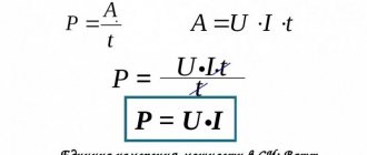
The general formula for AC power is:
P = I*U*cosϕ,
Where:
- P – power, (W);
- I – current, (A);
- U – voltage, (V);
- cosϕ – power factor.
The cosϕ value should tend to unity. The average power factor lies in the range of 0.7-0.8. The higher it is, the greater the efficiency of the installation.
In the case of 3-phase networks, the power will depend on the connection diagram of the source and load.
Three-phase current graph
Three-phase and single-phase networks
25.10.2019
As is well known to anyone who is at least a little interested in electrics, three-phase current flows through wires that transmit energy over long distances, because it is more profitable this way. In the apartment it appears with 1 phase, and the splitting of the three-phase circuit into 3 1-phase circuits goes to the ASU. A cable with 5 cores appears there, and a cable with 3 cores comes out.
But where are the other 2? The answer is surprising in its simplicity, because other apartments are powered by them. But this does not mean that the number of apartments is three. Their number depends only on the strength of the cables. Inside the shield, a three-phase circuit is disconnected into a single-phase circuit. To each phase going into the apartment, a zero is added and “grounding” is added, and at the output we see a cable with 3 cores.
In ideal situations, only a single zero should be present in three-phase networks. No more: the current moves in phases (relative to the others) by 1/3. Zero will be a neutral conductor, because it has no voltage. In three-phase networks, to which nothing is connected, there is precisely no voltage in the neutral conductors. What happens if the network is connected from a single-phase circuit? Phase 1 will go to one apartment, where there will be 1 refrigerator and 2 lamps.
Phase 2 will be in an apartment, where there will be 5 air conditioners, 2 PCs and an induction cooker and the like.
It's no secret that the load on such phases will not become uniform, so there will be no neutral conductor. And there will be tension on it, and also, the more identical the load is, the stronger it will be. The phases will no longer be able to compensate each other in such a way that the result is 0.
In the modern world, the situation with such uncontrolled current is worsening due to the fact that more and more new “pulse” devices are appearing. When they are connected, a much larger amount of energy begins to be consumed than during normal operation. Such devices, together with different loads on the phase, can also create conditions in which a voltage begins to arise in the “zeros”, which will have a force 2 times greater than in any other phases. The neutral has the same cross-section as the phase wire, but the load will be higher.
Therefore, more often there are cases called “burning 0” - neutral conductors cannot cope with the provided loads, so they burn out. Combating this phenomenon is labor-intensive: either increase the cross-section of the neutral wire (this is expensive), or distribute the load across 3 phases in equal shares (and this is unrealistic due to multi-apartment conditions). Or you can purchase a separating transformer.
Why use three-phase current
Knowing what three-phase current is, you can clearly answer the question why it is used.
How to connect a three-phase electric motor to a 220V network
Three-phase AC systems have a number of advantages that allow them to stand out among the multi-phase construction of electrical structures. The advantages include the following features:
- economical transportation of energy over long distances without reducing parameters;
- 3-phase transformers and cables have lower material consumption, unlike single-phase models;
- the ability to ensure a balanced energy system;
- simultaneous presence in installations of two voltages for operation: phase voltage (220 V) and linear voltage (380 V).
For your information. Connecting fluorescent lamps to different phases and installing them in one lamp will significantly reduce the stroboscopic effect and flicker noticeable to the eye.
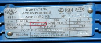
An integral part of the equipment of any manufacturing enterprise are asynchronous motors. For their normal operation and development of rated power, 3-phase power is required. It provides the possibility of forming a rotating MF (magnetic field), which drives the rotor of an asynchronous machine. Such motors are more economical, easier to manufacture and easy to operate compared to single-phase or any other.
At power plants of any type (hydroelectric power plant, nuclear power plant, thermal power plant), as well as alternative ones, the production of variable-type electricity is ensured using generators.
Three-phase power line 10 kV
Electric meter
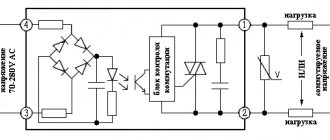
For any connection scheme, an electricity consumption meter is required. A 3-phase meter can be connected directly to the network (direct connection) or through a voltage transformer (semi-indirect), where the device readings are multiplied by a coefficient.
It is important to follow the connection order, where odd numbers are power and even numbers are load. The color of the wires is indicated in the description, and the diagram is located on the back cover of the device
The input and corresponding output of a 3-phase meter are indicated by the same color. The most common connection order is when the phases come first and the last wire is zero.
A 3-phase direct connection meter for a home is usually designed for a power of up to 60 kW.
Before choosing a multi-tariff model, you should coordinate the issue with the energy supply company. Modern devices with tarifficators make it possible to calculate electricity charges depending on the time of day, register and record power values over time.
The temperature readings of the devices are selected as widely as possible. On average they range from -20 to +50 °C. The service life of the devices reaches 40 years with a calibration interval of 5-10 years.
The meter is connected after the input three- or four-pole circuit breaker.
How does a generator work?
Three-phase meter: selection, installation, connection
The device works by converting rotational energy into electrical energy. The electric machine, using the rotation of the MP, generates electric current. At the moment when the wire winding (coil) rotates in the MF, the magnetic field lines penetrate the turns of the winding.
Attention! As a result of this process, electrons move towards the positive pole of the magnet. In this case, the current moves, on the contrary, towards the negative magnetic pole.
It doesn’t matter what rotates under mechanical action, a winding or a magnetic field, the current will flow as long as the rotation is performed.
Generators producing three-phase voltage may have:
- fixed magnets and a movable (rotating) armature;
- a stationary stator and magnetic poles that rotate.
In devices of the first design, there is a need to draw a large current at a high voltage. To do this, you have to use brushes (contacts sliding along slip rings).
The second generator structure is simpler and more in demand. Here the rotor is a moving element and consists of magnetic poles. The stator is a stationary part, assembled from a package of iron sheets insulated with each other and inserted into the grooves of the stator winding.
Information. The rotor has a body made of solid iron and has magnetic poles in the form of tips. Tips are assembled from separate sheets. Their shape is selected so that the generated current is close to a sinusoid in shape.
Pole cores have field coils. The coils are supplied with direct current. The feed is carried out through graphite brushes to the contact rings located on the shaft.
In the diagrams, a 3-phase generator is drawn as three windings, the angle between which is 1200.
There are several ways to excite generators, namely:
- independent - using a battery;
- from the exciter - using an additional generator mounted on one shaft;
- due to self-excitation - its own rectified current.
This also includes magnetic excitation supplied from permanent magnets.
Three-phase alternator
Three-phase network: power calculation, connection diagram
Not every average person understands what electrical circuits are. In apartments they are 99% single-phase, where the current flows to the consumer through one wire and returns through the other (zero). A three-phase network is a system for transmitting electric current that flows through three wires and returns one at a time. Here the return wire is not overloaded due to the phase shift of the current. Electricity is generated by a generator driven by an external drive.
An increase in the load in the circuit leads to an increase in the current passing through the generator windings. As a result, the magnetic field resists rotation of the drive shaft to a greater extent. The speed begins to decrease and the speed controller commands an increase in drive power, for example by supplying more fuel to the internal combustion engine. The speed is restored and more electricity is generated.
A three-phase system consists of 3 circuits with an EMF of the same frequency and a phase shift of 120°.
Three-phase circuit diagrams
The windings of a generator or transformer in three-phase circuits can be connected to each other according to two schemes:
- star;
- triangle.
Connections are made on the terminal block (boron) of the unit or transformer, where the ends of the windings are brought out.
Jumper connection of windings
Connecting the load to the generator (transformer) can be done according to the following schemes:
- star-star connection using a neutral conductor;
- star-star connection without using a neutral wire;
- star-delta connection;
- "triangle-triangle" scheme;
- delta-star connection.
Attention! This variety of circuits is due to the fact that the generator's own windings and the load's own windings can be connected in different ways. With different types of coupling, different correspondences between phase and linear values are obtained.
The connection can be made at the factory when assembling the generator; the second ends of the windings are already brought out to the point where the power cable is connected. Information about the winding connection diagram is applied to a plate attached to the stator of the machine.
On electric motors, transformers or other consumers, the necessary manipulations are also performed to switch winding terminals. In the picture below, the ends of the windings connected by a jumper are marked with a red marker. Blue marker - power phases.
Connections on boron motor
Star connection
The letter designation of the beginning of the windings is “A”, “B”, “C”, the ends are “X”, “Y”, “Z”. The zero point is marked “O”. Each winding has two ends. When connecting “star”, all three winding terminals of the same name (beginning) are connected to each other at one point “O”. The load is connected to the free ends.
Star winding connection diagram
Delta connection
When making this connection, jumpers are placed on the board, turning on the windings in the following sequence:
- the end of “A” - with the beginning of “B”;
- end “B” – with beginning “C”;
- the end of "C" - with the beginning of "A".
The graphic image of the coils becomes similar to a triangle, hence the name.
When they want to use a plug-in asynchronous motor with maximum efficiency, its windings are connected in a triangle. In this case, the phase voltages coincide (Ul = Uph), the line current will be calculated by the formula:
Il = √3*Iph.
When connecting a motor as a load, it is necessary to take into account a number of nuances:
- an increase in power by 1.5 times is achieved;
- the value of the starting current increases 7 times compared to the operating current due to difficult starting;
- a sharp increase in the load on the electric machine shaft will cause a sharp increase in current.
Because of all this, there is a risk of the machine overheating, which does not happen when the load windings are connected in a star configuration. There, the engine is not prone to overheating, and it starts smoothly.
Switching on the windings according to the "triangle" pattern
With two types of winding connection, two types of currents are distinguished and defined: linear and phase. It's easy to remember the differences:
- the current flowing through the conductor that connects the source to the receiver is called linear;
- The current moving through the windings of the source or load is called phase.
It is worth paying attention to the power formulas for various schemes for connecting the source to the load.
The current power in a star circuit is determined by the formula:
P = 3*Uф*Iф*cosϕ = √3*Uл*Iл*cosϕ,
Where:
- Uph – phase voltage;
- Uл – linear voltage;
- Iph – phase current;
- Il – linear current;
- cosϕ – phase shift.
The current power in a delta circuit is calculated by the formula:
P = 3* Uф* Iф*cosϕ = √3*Uл*Iл*cosϕ.
For your information. It is necessary to pay attention to linear and phase currents when the generator (source) is loaded asymmetrically when the load is connected.
Connections in a three-phase circuit
Single-phase alternating current and its parameters
Alternating current has not found practical use for a long time. This was due to the fact that the first electrical energy generators produced direct current, which fully satisfied the technological processes of electrochemistry, and direct current motors have good control characteristics.
However, as production developed, direct current became less and less suitable for the increasing requirements for economical power supply. Alternating current made it possible to effectively split electrical energy and change the voltage using transformers. It became possible to produce electricity at large power plants with its subsequent economical distribution to consumers, and the radius of power supply increased.
Currently, the central production and distribution of electrical energy is carried out mainly on alternating current. Circuits with changing - alternating - currents have a number of features compared to direct current circuits. Alternating currents and voltages cause alternating electric and magnetic fields. As a result of changes in these fields in circuits, the phenomena of self-induction and mutual induction arise, which have the most significant impact on the processes occurring in the circuits, complicating their analysis.
Alternating current (voltage, emf, etc.) is a current (voltage, emf, etc.) that varies over time. Currents whose values are repeated at regular intervals in the same sequence are called periodic, and the shortest period of time through which these repetitions are observed is called period T.
Basic parameters of single-phase alternating current circuits.
Single-phase industrial frequency alternating current has 50 oscillation periods per second, or 50 Hz. It is used to power small fans, household appliances, power tools, electric welding and to power most lighting devices. AC frequency, Hz:
f= 1/T = np/60,
where n is the generator rotation frequency, minˉ 1; p—number of generator pole pairs.
Single phase AC power:
active, W, Ra = IUcosφ;
reactive, var, Q = IUsinφ;
apparent, V A, S = IU =
If only active resistance is included in the single-phase alternating current circuit (for example, heating elements or electric lamps), then the value of current and power at each moment of time is determined by Ohm’s law:
I=U/R; Pa = IU = I²R=U²/R.
Power factor in a circuit with an inductive load
Cosφ= Pa/IU= Pa/S.
Basic concepts and quantities characterizing electrical circuits
Concepts:
An electrical circuit is a set of devices intended for the passage of electric current, the electromagnetic processes in which can be described using the concepts of voltage and current. In the general case, an electrical circuit consists of sources and receivers of electrical energy and intermediate links (wires, devices) connecting sources with receivers.
Sources of electrical energy are devices (galvanic cells, batteries, thermoelements, generators) in which the process of converting chemical, molecular-kinetic, thermal, mechanical or other types of energy into electrical energy occurs.
Receivers of electrical energy (load) are devices (electric lamps, electric heating devices, electric motors, resistors, capacitors, inductive coils) in which electrical energy is converted into light, heat, mechanical, etc.
Quantities:
Electric current and voltage are the main quantities characterizing the state of electrical circuits.
Electric current in conductors represents the phenomenon of ordered movement of electric charges. The term “current” also refers to the intensity or strength of current, measured by the amount of electric charge q passing through the cross-section of a conductor per unit time:
Therefore, current represents the rate of change of charge over time. In SI, charge is expressed in coulombs (C), time in seconds (s), and current in amperes (A).
Current as a ratio of two scalar quantities is a scalar algebraic quantity, the sign of which depends on the direction of movement of charges of the same sign, namely the conventionally accepted positive charge. To unambiguously determine the sign of the current in the positive direction, it is enough to arbitrarily select one of two possible directions, which is marked with an arrow.
If the movement of a positive charge occurs in the direction of the arrow, and the movement of a negative charge occurs towards it, then the current is positive. When the direction of movement of charges changes to the opposite, the current will be negative.
It is possible to uniquely set the current in the form of a certain function of time only after specifying the selected positive direction of the current. Therefore, before starting the analysis, it is necessary to note the positive directions of currents in all sections of the circuit, the choice of which can be arbitrary.
The passage of electric current or the transfer of charges in a circuit involves the conversion or consumption of energy. To determine the energy spent on moving a charge between the two points of the conductor under consideration, a new quantity is introduced—voltage.
Voltage is the amount of energy expended to move a unit of charge from one point to another:
, where w is energy.
When measuring energy in joules (J) and charge in coulombs (C), voltage is expressed in volts (V).
Stress as a ratio of two scalar quantities is also a scalar algebraic quantity. To unambiguously determine the sign of the voltage between the two terminals of the section of the circuit under consideration, one of the terminals is conventionally assigned a positive polarity, which is marked either with an arrow directed from the terminal or with the signs “+”, “-”
The voltage is positive if its polarity matches the selected one; this means that the potential of the terminal with the “+” sign, from which the arrow comes out, is higher than the potential of the second terminal.
Before starting the analysis, the selected positive voltage polarities must be indicated - only under this condition is it possible to unambiguously determine the voltages.
Although the conditionally positive voltage polarity can be chosen arbitrarily, it is usually convenient to choose it consistent with the selected positive current direction when the arrows for current and voltage coincide or the “+” sign of voltage polarity is at the tail of the arrow indicating the positive direction of current. With a consistent choice of polarity, it is obviously sufficient to limit yourself to indicating only one arrow in the positive direction of the current.
If there is a need to select a positive voltage polarity that is not consistent with the positive direction of the current, then you have to indicate two counter-directed arrows: for current and for voltage. This is not very convenient. Therefore, to denote conditionally positive polarity, we will use the signs “+.”, “-” at the terminals of a section of the circuit.
Power in an electrical circuit, equal to the product of voltage and current, is also an algebraic quantity. Its sign is determined by the signs of voltage and current: if these signs coincide, the power is positive, which corresponds to energy consumption in the section of the circuit under consideration; when the signs of voltage and current do not match, the power is negative, which means it is released from a section of the circuit (such a section is a source of energy).
Phase and line voltage in three-phase circuits
The next parameter that requires careful consideration is voltage. Just like currents, voltage in this case can be phase and linear. To make their difference clearer, it is best to consider a graphical representation of the voltage vectors (phases). It is already known that they are located at an angle of 1200 to each other. This is the angle between the windings of a three-phase generator.
location of voltage vectors on the diagram
While maintaining the angle of inclination of the vector Ub, they postpone it (changing the sign) from the point where the vector Ua ends. Then from the resulting vector diagram it is clear that the linear voltage vector Ul is equal to the distance between the starting point of the voltage vector Ua and the end point of the voltage vector Ub. It is noticeable that the linear voltage vector exceeds the phase voltage. How big this difference is can be determined using the formula:
Ul = 2*Ua*sin600.
Since sin600= √3/2, the formula takes the form:
Ul = √3*Ua = 1.73*Ua.
This means Ul = 1.73*Uф
In practical measurements of voltage parameters, phase voltage is measured by touching the tester probes to the phase and neutral conductors. The linear value should be measured by touching two phase conductors with probes.
Connecting a load to a source in a three-phase circuit can be carried out either via three wires, without a neutral conductor, or using it. It all depends on what type of neutral the network has. In networks with a solidly grounded neutral, the neutral conductor serves to avoid phase imbalance. In addition, it is used in protection circuits against insulation breakdown on equipment housings. It makes it possible for a protective shutdown to trip or for the fuse insert to blow out.
Networks with an isolated neutral work perfectly on three phase wires. Connections of this type exclude the simultaneous use of both phase and line voltage. With such a scheme, there is a risk of receiving an electric shock if the insulation breaks down.
Single-phase and three-phase electrical network
Hello, dear reader of the site Elesant.ru.
Electric current is “delivered” to the consumer via high-voltage power lines. The electric current of power lines has high voltage and cannot be directly used by consumers. For everyday use of the electric current delivered by the power line, its voltage must be reduced. For this purpose, special transformer substations are installed near consumers. Transformer substations reduce high-voltage voltage to rated values suitable for use. Let's stop a little at the substations.
Transformer substation
Transformer substations are electrical installations designed to receive, convert and distribute electricity from power lines.
Substations consist of a step-down transformer, switchgear (RU) and control devices.
Based on the method of construction and location, substations are divided into attached, built-in, and in-house. For suburban areas, mast and pole substations are the most common.
The main element of the substation is the step-down transformer. Step-down transformers can be three-phase or single-phase. Single-phase transformers are used in combination with three-phase transformers and mainly in rural areas.
The voltage in the transformers is reduced to a rated operating voltage of 380 or 220 volts. These voltages are called linear and phase, respectively. And the power supply to consumers is called three-phase and single-phase, respectively. Let us consider the types of consumer nutrition in more detail.
Single phase electrical supply
Single-phase power supplies the consumer from one phase line and the neutral working wire line. Lines for single-phase power supply are called single-phase electrical networks. The rated operating voltage of single-phase electrical networks is 220 volts.
Single-phase networks themselves can also be divided depending on the working conductors.
Single-phase two-wire network
In single-phase two-wire networks, two wires are used for power supply: phase (L) and neutral (N). Such an electrical network does not provide for grounding of electrical appliances. The two-wire electrical network was and remains the most common in the old housing stock.
If your home is wired with aluminum conductors, you most likely have a two-wire electrical network.
Single-phase three-wire network
In single-phase three-wire networks, three wires are used: phase (L), neutral (N) and protective, grounding. The third grounding wire is intended for additional protection of a person from electric shock. Connecting the grounding wire to the housings of electrical appliances (grounding) allows you to turn off the power supply when a phase wire is shorted to the housing of the device (short phase circuit). Designated PE.
Grounding not only protects a person from electric shock, but also saves the electrical appliances themselves from burnouts.
Three-phase electrical supply
With three-phase power supply, three supply phases (L1; L2; L3) and a neutral working conductor (N) are inserted into the electrical panel of an apartment or ASU at home. The rated operating voltage between any phase wires is 380 volts. The voltage between any phase wire and the working zero is 220 volts. From the electrical panel, the wiring is distributed throughout the apartment or house, according to the wiring diagram, providing 220 volt or 380 volt power for electrical appliances.
When calculating a three-phase electrical network, it is important to correctly distribute the load between the three phases. Uneven distribution of load between phases will lead to phase imbalance; severe phase imbalance will lead to an emergency situation, including burning out of one of the phases.
You can distribute three-phase power throughout an apartment or house using electrical cables with four or five wires
Three-phase four-wire electrical network
With four-wire wiring, the power supply comes from three phase wires and a working zero. From the electrical panel or distribution box, the wiring is distributed to sockets and lamps by two wires: each phase and neutral (L1-N; L2-N; L3-N). With a voltage of 220 volts. On diagrams, phases can be designated A, B, C.
Three-phase five-wire electrical network
In a three-phase five-wire electrical network, a fifth grounding wire “appears”, performing protective functions. Designated (PE)
Important! In all three-phase networks, it is important to distribute the load (power consumption) evenly between the phases. It is impossible to determine the network load with three-phase power supply according to the basic law of electrical engineering, Ohm's law. For calculations, it is necessary to take into account the power factor (cosph) and the demand factor (Kdemand). Usually for apartments cosф = 0.90-0.93; Ksprosa = 0.8. The value 0.8 is accepted if there are more than 5 consumers.
Normative references
Rules for Electrical Installations (PUE), edition 7.
Other articles in the section: Electrical networks
Source: https://elesant.ru/elektricheskie-seti-zhilogo-doma/odnofaznaya-i-trekhfaznaya-elektricheskaya-set
Differences from single-phase current
As a rule, three-phase alternating current is supplied to apartment buildings. This is due to the connection of a large number of single-phase loads. In this case, it is possible to evenly load each phase of the transformer substation circuit. This will prevent misalignment of the interphase and phase voltages.
The main differences, compared to single-phase current, lie in the following plane:
- line voltage is not designed to power single-phase consumers;
- the amount of load power depends on the cross-section of the supply cable;
- possibility of including three-phase consumers in the network;
- permissibility of switching a single-phase consumer to another phase.
In this regard, the use of three-phase current is more efficient in production.
Electricity distribution
Important! The cost of equipment, cable products, electricity, and metering devices when supplying a voltage of 380 V to an object is significantly higher than a single-phase network.
Which current option to choose, three-phase or single-phase, is up to the home owner to decide. This is especially true for large private houses, where modern electrical equipment requires the presence of all three phases. The costs of supplying 3-phase current and installing a metering unit will be more than recouped by the possibilities of using three-phase consumers in household farming.
Are single-phase networks found in their pure form?
The energy system of our country is designed to use a three-phase network. All generators in power plants produce three phases. This applies to hydroelectric power plants, nuclear power plants, thermal, tidal, etc.
This scheme for transmitting energy over long distances is the most economical. To transmit similar power with a single-phase line, large cross-section wires will be required. Therefore, single-phase networks are not used for electricity transmission.
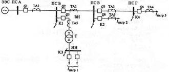
The figure below shows a diagram of the transmission of electricity from a thermal power plant to a consumer.
However, single-phase electrical networks are widely used as emergency power supplies.
For this purpose, gasoline or diesel power plants are used. Installed at facilities where power outages are unacceptable. For example, for powering hospitals (intensive care units or operating rooms), telephone exchanges, operational warning systems, etc. For powerful consumers, three-phase diesel generators are used. Material taken from the site: https://samelectrik.ru/
Video
Coffee capsules Nescafe Dolce Gusto Cappuccino, 8 servings (16 capsules)
435 ₽ More details
Coffee capsule Nescafe Dolce Gusto Cafe O Le Coffee with milk, 3 packs of 16 capsules each
1305 ₽ More details
Transceivers
Connection diagram of a three-phase motor to a three-phase network
The operation of three-phase electric motors is characterized by high performance and efficiency. No additional starting devices are required here
For normal operation, it is important to connect the device correctly and follow all recommendations
The connection diagram of a three-phase motor to a three-phase network creates a rotating magnetic field with three windings connected in a star or delta.
Each method has its own advantages and disadvantages. The star circuit allows the engine to start smoothly, but its power is reduced by up to 30%. This loss is absent in the delta circuit, but the current load is significantly greater at start-up.
The motors have a connection box where the winding terminals are located. If there are three of them, then the circuit is connected only by a star. With six terminals, the motor can be connected in any way.
Where is single-phase and three-phase voltage used?
The network comes out from the power plant in three phases, and they also supply power to modern houses. But in almost all buildings built in the former USSR, a three-phase network branches from the distribution panel; voltage is supplied to each apartment by one phase and a neutral wire.
A three-phase connection is usually used in private homes, since in addition to household electrical appliances, it is sometimes necessary to power powerful equipment such as a heating boiler, welding machine or circular saw.