Flaws
In addition to the positive qualities of solid-state relays, it is worth highlighting a number of disadvantages:
- When open, the product heats up due to the high resistance in the pn junction circuit. To avoid negative consequences in devices that pass high currents through themselves, it is necessary to provide cooling.
- When closed, the resistance increases and reverse leakage current appears (measured in mA).
- When taking the current-voltage characteristic, its nonlinear nature is noticeable.
- Some types of solid-state relays require strict polarity when connecting output circuits. This applies to those devices that are designed to operate in direct current conditions.
- In the event of a breakdown, there is a high risk of blocking the input contacts. The reason may be a breakdown of the power switch. For comparison, the contacts of classic relays (if they fail) remain open.
- Protection against erroneous operations caused by voltage surges is required. This is due to the high response speed.
- Solid-state relays pass current along the return path with a slight delay, which is due to the use of semiconductor elements in the circuit.
Tips for choosing
Overload protector
You can buy solid-state relays only in a specialized electronics store. Experienced specialists will help you choose the best device for specific purposes. The cost of the product is influenced by the following factors:
- relay type;
- presence of locking mechanisms;
- body material;
- on time;
- manufacturer and country of production;
- power;
- required energy;
- dimensions.
When purchasing, it is important to take into account that there must be a power reserve that is several times greater than the working one. This will protect the relay from damage
Special fuses are also used additionally. The most reliable include:
- GR – used in a wide range of loads, characterized by high performance.
- GS – operate over the entire current range. Reliably protect the device from excess load of the electrical network.
- AR - protects semiconductor device components from short circuits.
Such devices provide high protection against breakdowns. Their cost is comparable to the price of the relay itself. Fuses of classes B, C, D have lower protective properties and, accordingly, lower cost.
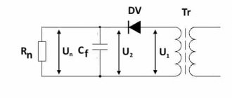
Design
A solid-state relay device is an electronic board consisting of a power switch, an isolation element and a control unit. The following can be used as power elements:
- for DC circuits: transistors, field-effect transistors, MOSFETs or IGBT modules.
- To control circuits with alternating voltage, triac switches or thyristor assemblies are installed.
Optocouplers are installed as an isolation element - this device consists of a light-emitting element and a photo receiver, separated by a transparent dielectric. The control unit is a voltage and current stabilization circuit for the light-emitting element in the optocoupler.
As can be seen from the diagram, the control inputs are numbered 3 and 4, and the output is terminals 1 and 2. In this circuit, the input signal can be from 70 volts to 280 AC voltage, and the load voltage can reach 480 volts. It does not matter which contact the consumer is located on, before or after the relay.
The symbol for a solid-state relay in the diagram may look like this (click on the picture to enlarge):
As for the connection diagram, in it the device is installed after the load, connecting it to the ground. With this connection, in the event of a short circuit to ground, the relay is excluded from the current flow circuit.
Finally, we recommend watching a video that clearly demonstrates how a solid-state relay works and what it consists of:
So we looked at the purpose, scope and design of a solid-state relay. We hope the information provided was useful and understandable!
You probably don't know:
- Why do you need relay protection?
- How does a magnetic starter work?
- Remote lighting control systems
Famous models
Explanation of markings
The main characteristics depend on many factors. Popular domestic models produced by KIPprbor, Proton, Cosmo include:
- TM-O. Devices with a built-in “zero” circuit through which a phase transition passes.
- TS. Models that turn off at any time.
- The most popular and used are TMB, TSB, TSM, TMB, TSA. They have an RC output circuit.
- Тс/ТМ – power. Currents reach values of 25 mA.
- TSA, TMA - used in sensitive instruments.
- TSB, TMB – low-voltage models. The voltage does not exceed 30 V.
- TSV, TMV - high voltage. The voltage reaches 280 V.
Foreign analogues include products manufactured by Carlo Gavazzi, Gefran, CPC.
Decoding
Models SSR, TSR (single-phase and three-phase, respectively) are the most popular. Their resistance is 50 MΩ or more at a voltage of 500 V.
The designation is written as SSR -40 DA H. SSR or TSR indicates the number of phases. 40 – load in Amperes. The letter indicates the input signal (L 4-20 mA, D – 3-32 V at DC, V – variable resistance, A – 80-250 V at AC). The next letter is the input voltage (A - alternating, D - constant). The last letter is the output voltage range (H - 90-480 V, no letter - 24-380 V).
Three Phase Solid State Relay
Relay Features
- Long service life
- Control with switching when current passes through zero
- Control voltage 3 - 32 V DC, 70 - 280 V AC
- 3-phase switching
- No contact bounce or sparking during switching
- Low electromagnetic interference
- High insulation resistance between switching and control circuits
- No acoustic noise
- High performance
Solid-state relays with zero-crossing switching pass 0 or 100% of the power. When the thermal controller operates with such solid-state relays, maintaining the set temperature is possible with on-off control by changing the ratio of the load on/off time. For smooth power control, 3-phase solid-state relays with phase control are used.
Decoding of nomenclature
- GDH — Type of solid state relay
- GDH - single-phase solid state relay (10 - 120 A)
- GDM - single-phase solid-state relays in an industrial housing (100 - 500 A)
- GTH - three-phase solid state relays (10 - 120 A)
- GTR - three-phase reversible solid-state relays (10 - 40 A)
- 40 — operating current 40 A (from 10 to 500 A)
- 48 — operating voltage 24 — 480 V AC, 38 — 24 — 380 V AC, 23 — 5 — 220 V DC
- ZD3 — type of control signal (switching method
)- VA - variable resistor 470 - 560 kOhm / 2 W ( phase control
) - LA - analog signal 4 - 20 mA ( phase control
) - VD - analog signal 0 - 10 V DC ( phase control
) - ZD - control 10 - 30 V DC ( zero crossing switching
) - ZD3 - control 3 - 32 V DC ( switching at zero crossing
) - ZA2 - control 70 - 280 V AC ( zero crossing switching
) - DD3 - control 3 - 32 V DC ( DC voltage switching
)
Design options
| Output voltage | Control voltage | Rated switching current | ||
| 10 A | 25 A | 40 A | ||
| 480 V AC "switch" at 0" | 3 - 32 V DC | GTH1048ZD3 | GTH2548ZD3 | GTH4048ZD3 |
| 70 – 280 V AC | GTH1048ZA2 | GTH2548ZA2 | GTH4048ZA2 | |
| Output voltage | Control voltage | Rated switching current | |||
| 60 A | 80 A | 100 A | 120 A | ||
| 480 V AC "switch" at 0" | 3 - 32 V DC | GTH6048ZD3 | GTH8048ZD3 | GTH10048ZD3 | GTH12048ZD3 |
| 70 – 280 V AC | GTH6048ZA2 | GTH8048ZA2 | GTH10048ZA2 | GTH12048ZA2 | |
Technical characteristics and operating conditions
| Modification of solid state relay | GTHxxxxxZD3 | GTHxxxxxZA2 |
| Switching voltage | 24 - 480 V AC | |
| Control voltage | 3 - 32 V DC | 70 – 280 V AC |
| Current consumption in the control circuit | 10 - 68 mA | ≤12 mA |
| Voltage on/off | 3 V DC / 1.5 V DC | 70 V AC / 10 V AC |
| Maximum peak voltage | 1000 V AC | |
| Voltage drop in load circuit | ≤1.6 V AC | |
| Leakage current (off state) | ≤10 mA | |
| Switching time | ≤10ms | |
| Power-on indication | There is | |
| Breakdown voltage | 2500 V AC during 1 minutes | |
| Insulation resistance | 500 MΩ at 500 V DC | |
| Ambient temperature | — 30…+ 75°C | |
| Relative humidity | ≤95% (no condensation) | |
| dimensions | 105x74x33mm | |
| Installation method | Screws onto mounting surface | |
| Weight | ≤450g | |
Connection diagrams
GTHxxxxxZD3
GTHxxxxxZA2
Appearance and overall dimensions
| Name | Price | Order |
| GTH1048ZD3 10A, control 3…32V DC, 480V AC | 34$ | |
| GTH2548ZD3 25A, control 3…32V DC, 480V AC | 44$ | |
| GTH4048ZD3 40A, control 3…32V DC, 480V AC | 53$ | |
| GTH6048ZD3 60A, control 3…32V DC, 480V AC | 62$ | |
| GTH8048ZD3 80A, control 3…32V DC, 480V AC | 75$ | |
| GTH10048ZD3 100A, control 3…32V DC, 480V AC | 93$ | |
| GTH12048ZD3 120A, control 3…32V DC, 480V AC | 107$ | |
| GTH1048ZA2 10A, control 90…250V AC, 480V AC | 37$ | |
| GTH2548ZA2 25A, control 90…250V AC, 480V AC | 46$ | |
| GTH4048ZA2 40A, control 90…250V AC, 480V AC | 55$ | |
| GTH6048ZA2 60A, control 90…250V AC, 480V AC | 64$ | |
| GTH8048ZA2 80A, control 90…250V AC, 480V AC | 76$ | |
| GTH10048ZA2 100A, control 90…250V AC, 480V AC | 94$ | |
| GTH12048ZA2 120A, control 90…250V AC, 480V AC | 117$ |
Connecting a solid state relay
The connection principle is simple. The device has control inputs (voltage is supplied to them with strict polarity) and an output for connecting a load. An important point is the quality of the connection. The screw method is used here (soldering is excluded).
To avoid damage to the SSR, it is important to prevent dust and foreign mechanical elements from coming into contact with the contacts. It is worth taking measures to prevent negative impacts on the device casing (on or off)
After switching on, do not touch the body, which may be hot.
Please note that the TSR is not located near flammable materials. In addition, during the connection process, make sure that the connection is completed without errors
If, after switching on, the product reaches a temperature above 60 degrees Celsius, install a radiator on it for cooling (the reasons and features of this protective measure are discussed above).
If nothing is done, the device will stop working when it reaches 80 degrees Celsius. Control is carried out using a chain with various design options.
Practical application of devices
The scope of use of solid-state relays is quite extensive. Due to their high reliability and lack of need for regular maintenance, they are often installed in hard-to-reach places on equipment.
In many relays, connecting the control circuit wires requires polarity, which must be taken into account during equipment installation
The main areas of application of TTP are:
- thermoregulation system using heating elements;
- maintaining stable temperatures in technological processes;
- control of transformers;
- lighting adjustment;
- diagrams of motion sensors, lighting, photo sensors for street lighting, etc.;
- electric motor control;
- uninterruptible power supplies.
With the increasing automation of household appliances, solid-state relays are becoming increasingly common, and developing semiconductor technologies are constantly opening up new areas of their application.
Types of TTP
Solid-state relays according to their design and operating principle can be divided into the following types:
- By type of control voltage - alternating or constant (discrete). Sometimes a variable resistor is connected to the input, i.e. analog control is used, and accordingly the output voltage changes smoothly, like in a dimmer for lighting.
- Depending on the type of switched voltage - alternating or direct.
- According to the number of phases for alternating voltage - one or three.
- For three-phase - with or without reverse.
- Design: surface or DIN rail mounting. Although, almost all manufacturers offer adapter strips for universal installation.
In addition, the standard option for switching AC voltage is switching at the moment of zero crossing.
Above there was already a photo of TTL, whose input is constant voltage, output is alternating (AC-DC). Here are some other relays I have on hand right now:
SSR OMRON DC-DC. Input – constant voltage up to 24 V, output – also constant, up to 200 V
SSR FOTEK DC-DC – Solid State DC Relays
These two relay models are convenient for switching a load with a constant voltage of 24 Volts, when the control signal (also 24 V) comes from the output of the controller or from the sensor. We can say that these are compact current amplifiers. Moreover, the gain in this case is about 1000, since the control circuit current is less than 10 mA.
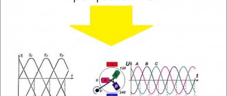
Further more. Below is a three phase solid state relay. Three phases of 380V are supplied to its inputs R, S, T, and from its outputs U, V, W the voltage is supplied to an asynchronous motor or three-phase heating element.
Fotek 3 phase. Three Phase Solid State Relay
This relay works (based on the results of its operation) approximately like a magnetic starter with a 24 VDC coil.
How to connect an electric motor through a magnetic starter is described in detail on SamElectrika here.
The control contacts are shown closer:
Fotek 3 phase. Input control contacts
Do you see in the photo that there is one more place for the control contacts, which is not used in this case? At this point, another model has a reverse signal. That is, when applied to one input, the phases are switched through a relay for forward rotation of the engine, and when applied to another input, for reverse rotation.
For those who don’t know, direct rotation is when the engine rotates clockwise when looking at its rear. How to change the direction of rotation of the motor - swap any two phases.
On the topic, I recommend reading my article on three phases and the differences between three-phase power and single-phase power.
Three-phase relays with reverse come with switching of two phases, the third is constantly connected to the motor.
Now imagine how much space it takes up and how much noise a conventional reversing relay with such a current creates during operation? That's it!
Here is the same TTL, but more powerful and controlled by 220V AC.
Fotek TSR-40AA-H 3 phase 40A
It seems like everything, write who has any experience in using it!
Here are some files I dug up that are freely available; perhaps they are written more informatively than mine:
Solid State Relays by Switching Type
With zero crossing switching
Look closely at the diagram
Such SSRs switch alternating current at the output. As you can see here, when we apply a constant voltage to the input of such a relay, switching at the output does not occur immediately, but only when the alternating current reaches zero. Shutdown occurs in a similar way.
Why is this being done? In order to reduce the influence of interference on the loads and reduce the pulse current surge, which can lead to load failure, especially if the load is a circuit based on semiconductor radio elements.
The connection diagram and internal structure of such a SSR looks something like this:
DC control
AC control
Instant on
Everything is much simpler here. Such a relay immediately begins to switch the load when control voltage appears on it. The diagram shows that the output voltage appeared immediately as soon as we applied the control voltage to the input. When we already remove the control voltage, the relay turns off in the same way as the SSR with zero crossing control.
What is the disadvantage of this TTP? When a control voltage is applied to the input, current surges may occur at the output, and as a result, electromagnetic interference. Therefore, this type of relay is not recommended for use in radio-electronic devices where there are data transmission buses, since in this case interference can significantly interfere with the transmission of information signals.
The internal structure of the SSR and the load connection diagram look something like this:
With phase control
Everything is much simpler here. By changing the resistance value, we thereby change the power at the load.
An approximate connection diagram looks like this:
Advantages and disadvantages
Unlike other types of relays, solid state relays have no moving contacts. Switching of electrical circuits in this device is carried out according to the principle of an electronic key made on semiconductors. To avoid problems when creating a solid-state relay, you need to understand the operating principle of the device and its design.
However, it’s worth starting with a description of its main advantages:
- Ability to switch powerful loads.
- Switching occurs at high speed.
- High-quality galvanic isolation.
- Capable of withstanding severe overloads for a short period of time.
No mechanical relay has similar parameters. The scope of application of solid state relays (SSR) is practically unlimited. The absence of moving elements in the design significantly increases the service life of the device. However, it should be remembered that the device has not only advantages. Some properties of TTP are disadvantages. For example, during the operation of powerful devices, it becomes necessary to use an additional element to remove thermal energy.
Often the dimensions of the radiator significantly exceed the dimensions of the relay itself. In such a situation, installation of the device is somewhat difficult. When the device is closed, current leakage is observed in it, which leads to the appearance of a nonlinear current-voltage characteristic
Thus, when using SSRs, you should pay attention to the characteristics of the switched voltages. Some types of devices can only operate in DC networks
When connecting a solid-state relay to a circuit, it is necessary to provide methods of protection against false alarms.
Types of solid state relay loads. General classification
Inductive load – an electrical load with a large inductive component. This load includes electrical devices that contain electric coils or windings: valve solenoids, transformers, electric motors, chokes, etc.
A feature of an inductive load is the high current consumption when it is turned on (inrush currents) caused by transient electrical processes. Inrush currents of a highly inductive load can exceed the rated current by several tens of times and can be quite long-lasting, therefore, when using a solid-state relay to switch an inductive load, it is necessary to select the rating of the solid-state relay (SSR) taking into account the inrush currents of the load.
Resistive load - an electrical load in the form of a resistance (resistor), which converts electrical energy into thermal energy.
Most heaters (heating elements) are resistive loads. Resistive-type loads are characterized by relatively low inrush currents, which makes it possible to use solid-state relays with a minimum current margin (usually a 25% margin) for switching a resistive load. But there are exceptions, a striking example is incandescent lamps, although they are essentially a resistive load, but have fairly high starting currents (up to 12 * In), which is due to the very large variation in the resistance of the nichrome spiral at different temperatures.
A heating element is a heater in the form of a metal tube filled with a heat-conducting electrical insulator, in the center of which a heating element of a certain resistance is installed. A nichrome thread is usually used as a heating element. The heating element refers to a resistive type load with low inrush currents.
Reversing solid state relays
There are also special three-phase solid-state relays for reversing motors that have two control inputs.
An example of turning on a three-phase relay is in the photo below:
Turning on a three-phase solid state relay
As you can see, the relay is not entirely three-phase; one phase is constantly supplied to the motor, which can cause danger.
Its connection diagram is printed on the relay body, where everything is clear. The relay is reversible, and it has two inputs - Forward and Reverse (Forward/Back). To reverse, phases L1 and L2 are swapped.
Important - there is no blocking inside the relay from simultaneous activation in both directions, and it must be provided in hardware (locking contacts of buttons/relays) and software (if control is from the controller). If this is not provided for, then a situation is likely where power outputs 1, 2, 3, 4 will be short-circuited