How will phase currents change if a line wire breaks?
Line wire break (for example, A). In this mode, the current and voltage across the load Z bc
will not change, but at loads
Z ab
and
Z ca
will decrease by 2 times, since they are connected in series under the same voltage
U BC
(Fig. 10.5,
c
).
Linear currents I B
and
I C
will be equal to 1.5
I f
and, therefore, will decrease compared to the original symmetrical mode, when they were equal
(Fig. 10.5, c
).
How to determine phase imbalance
The simplest and therefore most used is control of the maximum deviation of phase currents. Using current clamps, the current strength is measured at the maximum full load on each conductor of an individual phase in an ASU or distribution switchboard. The dimensions of the pliers are compact enough to get to any conductor located in cramped conditions among other conductors.
After you determine and record the readings, you should perform an easy comparative calculation for phase current deviations. Indications must comply with the standards.
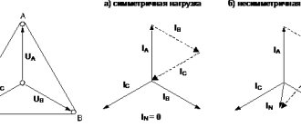
How will line currents change if a line wire breaks?
How will the currents change in the phases of the receiver when the line wire breaks
A. [1]
Construct a vector diagram of voltages and currents when a linear wire of a three-phase network is broken
and give considerations about the impact of this type of damage on the operating mode of individual receivers. [2]
How will the currents or voltages in the circuit change when the line wire breaks
or phase short circuit. Similar modes occur when there is a malfunction in the energy receivers, a blown fuse, or other anomalies in the circuit. [3]
From the diagram in Fig. 4.26 it can be seen that if the line wire breaks
And phases ab and ca will be connected in series and, therefore, their total resistance will double. [4]
Thus, in the case of a triangle connection when the line wire breaks
The consumer's power is halved. [5]
Lighting network.| Special cases of asymmetrical load.
The diagram shows that a three-phase AC system when a line wire breaks
turned into single-phase. [6]
If there is a neutral wire for electrical receivers connected to undamaged line wires, a break in someone else's line wire
it is practically not felt. In the absence of a neutral wire, the phase voltages at the terminals of both series-connected electrical receivers are proportional to the values of their impedances. The predominance of an inductive load in one of these phases, and a capacitive load in the other, can lead to voltage resonance with the establishment of significant overvoltages at the terminals of electrical receivers and a sharp increase in current consumption. [7]
The stationary TsPA-P remote control allows you to test the brakes and identify the main faults of electro-pneumatic brakes: broken line wire
or its branches, malfunction of electric air distributors and inter-car connections, to
Standards for phase imbalance
In practice, there are no working three-phase networks in which there is no phase imbalance. This is due to the peculiarities of electrical equipment, the operating principle of which, from the point of view of economic feasibility, excludes symmetrical design (welding machines, induction furnaces, household consumers). In addition, for example, in apartment buildings there is a probabilistic factor associated with the lack of any system for connecting electrical household appliances. The presence of several switching power supplies, for example for computers, makes their behavior unpredictable in a three-phase network.
In addition to evenly distributing the load across phases, designers should consider the above factors to deliver a certain quality of power to users. In some cases, an intractable problem can be solved by regulations on permissible phase misalignment, indicated in the following regulatory documents: PUE (Rules for the Construction of Power Installations), GOST 31098 - 97 defining power quality standards and the set of rules SP31-110.
Parameters that must not be exceeded:
- maximum deviation of phase currents: for those measured in the input switchgear (IDU) - 15%,
- for those measured in the distribution board (DP) - 30%.
- in reverse sequence - 2%,
The above standards must be observed in all possible operating modes of three-phase electrical networks. Exceptions are regimes caused by Force Majeure circumstances.
Elimination of phase imbalance
If the measurement results reveal the presence of phase voltage asymmetry, measures should be taken to eliminate the imbalance. Protection against phase imbalance in a three-phase network is performed in the following ways.
- At the design stage, the load should be evenly distributed among the phases. Devices with single-phase power supply should not focus on one conductor, leaving others unloaded. In addition to the quantitative distribution by phase, the power characteristics of electrical devices should be taken into account.
- In previously commissioned three-phase networks, where each phase was not designed for overload, if possible, the energy consumption pattern should be changed. In a crisis situation, it is necessary to change the consumer's power.
- An insufficiently effective way to provide the required voltage on each phase of a three-phase circuit is the use of voltage stabilizers.
Three-phase voltage stabilizers structurally include single-phase ones, which respond to changes in parameters specifically in their phase. Raising and lowering tension causes a response to others. This may in some cases cause a secondary distortion with different parameters. The impossibility of 100% guarantee of protection against the consequences of phase imbalance is the main drawback of voltage stabilizers. - The use of a balun transformer in a three-phase power system allows you to equalize the voltage not only on a single specific phase, but to ensure the symmetry of the voltages on all three in accordance with the required standards.
In addition, the device smoothes out the transient voltage when connecting powerful asynchronous motors, chokes, transformers and other similar equipment to the network. The device is able to eliminate phase imbalance in a wide range of voltage values. - A voltage stabilizer and balun transformer are expensive devices, and it is not always possible to use them. There is a fairly simple and effective way to prevent critical phase imbalance - the use of a special relay.
If the three-phase network parameters fall outside the set range, the relay will turn off the power source. When the parameters are restored to acceptable values, the relay will automatically resume power supply.
A responsible attitude towards uniform distribution of the load across phases does not guarantee the avoidance of imbalance. No one is safe from a break in the neutral wire; the connecting contact can “burn out” at any time due to overheating. Therefore, recommendations for equipping a three-phase network with skewing protection devices should be heeded. One-time costs will preserve the functionality of more expensive electrical equipment operating from a three-phase network.
Possible consequences
The consequences of a zero break in a three-phase network are sometimes extremely dangerous. Regardless of the grounding system used, when the neutral core burns out, high potentials appear in apartments connected to such a cable. Due to severe distortion, voltages reaching 380 Volts will appear on some electrical wiring lines. On other branches from the 3-phase input, on the contrary, they can drop to almost zero.
Breaks in the neutral wire are dangerous because they, first of all, pose a threat to household devices connected to sockets. This can lead to complete failure of expensive equipment or ignition of old aluminum electrical wiring, which can lead to a fire. On the other hand, if the house is connected through a TN-C system with combined PE and N conductors, a break in the common PEN core will result in the loss of the protective function that protects against electric shock. In the absence of re-grounding, the consumer will be defenseless if the PEN wire breaks, even if he has an RCD installed in his apartment, which cannot work without a neutral wire.
If a zero break occurs on one of the apartment lines, protected by a separate circuit breaker, first of all, all electrical devices connected to it will stop working. In addition, if there is no zero and there is a phase in the network, a dangerous potential of 220 Volts will reach the ground terminal through constantly switched on loads. As a result, there will be one more phase in the socket, which is very dangerous in the absence of normal grounding.
In the event of any accidental breakdown of insulation in a washing machine, for example, the dangerous potential will have nowhere to flow, since the ground wire is broken. For a consumer standing on a concrete floor connected to the ground, this poses a great danger, since all the current will flow through it.
Short circuit in a circuit powered by constant voltage buses
Figure 1 shows a simple symmetrical three-phase circuit with active inductive reactance, which is typical for most real electrical networks. The circuit is powered from a source that, in normal operation and during a short circuit, maintains a symmetrical and unchanged three-phase voltage system at the terminals. The vector diagram of the circuit under consideration for normal operation is shown in Fig. 2, a. The angle φ between the current and voltage of each phase is determined by the ratio of the active and inductive reactances of the entire circuit, including the load.
Fig.1. Three-phase symmetrical circuit powered from constant voltage busbars (from an infinite power source)
Fig.2. Vector diagrams of currents and voltages: a - in normal mode; b - with a three-phase short circuit
A short circuit divides the circuit into two parts: the right with resistances r1 and x1 = ωL1 in each phase and the left, containing the power source and short-circuit resistances rK and xK = ωLK. Processes in both parts of the circuit during a three-phase short circuit proceed independently.
The right side of the circuit under consideration turns out to be shunted by a short circuit, and the current in it will be maintained only until the magnetic field energy stored in inductance L1 is converted into heat released in the active resistance r1. This current, with the active-inductive nature of the circuit resistance, does not exceed the normal mode current and, gradually attenuating to zero, does not pose a danger to the equipment.
A change in mode on the left side of the circuit containing the power source, in the presence of inductance LK, is also accompanied by a transient process. From the course “Theoretical Foundations of Electrical Engineering” we know the equation that describes this process:
(1)
where u and i are the instantaneous values of voltage and current of the phase under consideration, respectively.
Solving this equation gives an expression for the instantaneous value of the current at any time t from the beginning of the fault:
(2)
where Um is the amplitude value of the phase voltage of the source; ZK is the total resistance of the circuit section connected to the source (short-circuit circuit); α is the phase angle of the source voltage at the moment t = 0; φK is the shift angle of the current in the short-circuit circuit relative to the source voltage of the same phase; Ta is the time constant of the short-circuit circuit:
(3)
As can be seen from (2), the total short-circuit current consists of two components: forced, due to the action of the source voltage (the first term on the right side of the equation), and free, due to the change in the magnetic field energy reserve in the inductance LK (the second term of the equation).
The forced component of the short-circuit current is periodic in nature with a frequency equal to the frequency of the source voltage. This component is usually called the periodic component of the short-circuit current
(4)
where Iп,m is the amplitude value of the periodic component of the current.
The shift angle φK between the current and voltage vectors is determined by the ratio of the active and inductive resistances of the short-circuit circuit. For real circuits, usually xK » rK and φK = 45-90°. The vector diagram for the periodic component of the short circuit at φK = 90° is shown in Fig. 2b. Free current component
(5)
has an aperiodic nature of change, on the basis of which this current component is also called the aperiodic component of the short-circuit current.
The initial value of the aperiodic component of the short-circuit current in each phase is determined by expression (2) for time t=0:
(6)
here iK,0 is the initial value of the short-circuit current, which, taking into account the impossibility of changing the current abruptly in a circuit with inductance, is equal to i(0) - the current of the previous mode in a given phase at the moment t=0. The value of the periodic component of the current at t=0 is determined as
(7)
Of particular interest are the conditions for the occurrence of the maximum possible value of the total short-circuit current and its aperiodic component. From (6) and (7) with xK » rK and φK≈90° it follows that the maximum current value ia,0 will be if the voltage at the moment of the short circuit passes through the zero value (α=0) and the current in the circuit is up to There is no short circuit, i.e. i(0)=0. In this case, ia,0=Iп,m. The current change curve under the condition of the maximum value of the aperiodic current component is shown in Fig. 4. Here ia,0=Iп,m.
Fig.3. Change in short-circuit current in a circuit fed from constant voltage buses at the maximum value of the aperiodic component
The maximum instantaneous value of the total current usually occurs 0.01 s after the start of the short-circuit process (Fig. 3). It is called shock current and is designated iy. The shock current will be determined from (2) for the moment t=0.01s:
(8)
or
(9)
where ky is the shock coefficient depending on the time constant of the short-circuit circuit:
(10)
The transient process in the case of power supply from constant voltage buses ends after the aperiodic component of the current has attenuated, and then the total short-circuit current is equal to its periodic component, unchanged in amplitude.
The effective value of the current for an arbitrary short circuit time t is equal to:
periodic component
(11)
aperiodic component
(12)
full short circuit current
(13)
Consequences of a zero break in a three-phase network
I'll tell you stories from my life.
- Electricians were repairing the entrance to the entrance. And during the repair, the working zero was turned off for a few seconds. A very unpleasant thing happened: when people returned home in the evening, they discovered that their TVs, refrigerators, chargers, etc. had burned out. - something that is constantly plugged into our outlets. It's good that there hasn't been a fire yet.
- Came on call, complained - tension was floating. I measure the voltage (everything is turned off) - almost 300 volts. Then, when the incandescent lamp is turned on, the voltage drops to 70V... It turned out that a bolt had burnt out in the floor panel, which received a zero. There was a break in the zero, a phase imbalance, and voltages went wild. I replaced the bolt, restored contact, and the voltage returned to normal.
Scratch bolt. Rusty, periodically does not contact!!! If you change it without turning it off, 100% of the equipment in the entrance will burn out!
An article on how I changed the electrical panel there is here.
- I was called to an advertising and publishing company. According to preliminary estimates, the damage is more than 100 thousand rubles, and all due to poor contact on the zero bus:
Zero burnout from the zero bus
The neutral wire burned off from the second bolt. You can see how it fell off under tension. Before falling off, it ALMOST melted the insulation of the phase wires (vertical, red and white).
The server has not been turned on yet, perhaps the intellectual damage will be greater...
At the site of this tragedy, I installed a three-phase voltage relay Barrier, read the article at the link.
As you can see, such problems occur due to incorrect actions of “electricians” or due to spontaneous breakage (burnout) of the neutral wire in the old housing stock.
In this article I will tell you in detail why this happens and how to deal with it.