Three-phase load connected in star connection
If the loads (receivers) are connected in a three-phase circuit according to the “star” circuit (Fig. 1), then phase voltages are applied to the load resistances. Linear currents are equal to phase currents and are determined by Ohm’s law:
and the current in the neutral is equal to the vector sum of these currents: I N
=
I A
+
I B
+
I C
.
Fig.1
At symmetrical voltages UA
,
UB
,
UC
and the same resistances
RA
=
RB
=
RC
=
R
the currents
IA
,
IB
,
IC
are also symmetrical and their vector sum (
IN
) is zero. Then
IL =
IФ
=
UФ ¤ R
;
IN
= 0.
If the load phase resistances are not the same, then some current IN
No. 0. This is illustrated in vector diagrams (Fig. 2).
Fig.2.
The power of a three-phase load is the sum of the phase powers: S P =
PA + PV + PC.
When the load is symmetrical and purely resistive, we have
S P = 3
PF
=
3 UФ × IФ
.
With a mixed (active-inductive or active-capacitive) load:
Active power
S P = 3
× UФ × IФ × cos j = Ö3 × UL × IL × cos j
.
Reactive power
S Q = 3
× UФ × IФ × sin j
=
Ö3 × UL × IL × sin j
.
Full power
S S = 3
× UФ IФ = Ö3 × UЛ × IЛ
.
Calculation of a three-phase circuit connected by a star
Triangle connection. Scheme, definitions
Star connection. Scheme, definitions
If the ends of all phases of the generator are connected into a common node, and the beginnings of the phases are connected to a load that forms a three-pointed star of resistance, you will get a three-phase circuit connected by a star. In this case, the three return wires merge into one, called zero or neutral. A three-phase circuit connected by a star is shown in Fig. 7. 1.
Rice. 7.1
The wires going from the source to the load are called linear wires, the wire connecting the neutral points of the source N and the receiver N' is called the neutral (zero) wire.
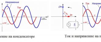
The voltages between the beginnings of phases or between linear wires are called linear voltages. The voltages between the beginning and end of a phase or between the line and neutral wires are called phase voltages.
Currents in the phases of the receiver or source are called phase currents, currents in linear wires are called linear currents. Since the linear wires are connected in series with the phases of the source and receiver, the linear currents when connected by a star are simultaneously phase currents.
Iл = Iф.
ZN is the resistance of the neutral wire.
Linear voltages are equal to the geometric differences of the corresponding phase voltages
(7.1)
In Fig. Figure 7.2 shows a vector diagram of phase and line voltages of a symmetrical source.
Rice. 7.2
From the vector diagram it can be seen that
With a symmetrical system of EMF source, the linear voltage is √3 times greater than the phase voltage.
Ul = √3 Uph
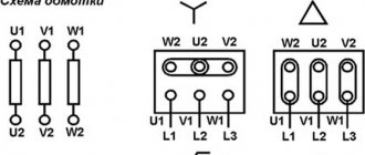
If the end of each phase of the generator winding is connected to the beginning of the next phase, a delta connection is formed. Three line wires leading to the load are connected to the winding connection points. In Fig. Figure 7.3 shows a three-phase circuit connected by a delta. As can be seen from Fig. 7.3, in a three-phase circuit connected by a triangle, the phase and line voltages are the same.
Ul = Uф
IA, IB, IC - linear currents;
Iab, Ibc, Ica - phase currents.
Linear and phase load currents are related to each other by Kirchhoff’s first law for nodes a, b, c.
Rice. 7.3
The line current is equal to the geometric difference of the corresponding phase currents. In Fig. Figure 7.4 shows a vector diagram of a three-phase circuit connected by a triangle with a symmetrical load. The load is symmetrical if the phase resistances are the same. The vectors of phase currents coincide in direction with the vectors of the corresponding phase voltages, since the load consists of active resistances.
Rice. 7.4
From the vector diagram it can be seen that
,
Il = √3 Iph with symmetrical load.
Three-phase star-connected circuits have become more common than three-phase delta-connected circuits. This is explained by the fact that, firstly, in a circuit connected by a star, two voltages can be obtained: linear and phase. Secondly, if the phases of the winding of an electric machine connected by a delta are under unequal conditions, additional currents appear in the winding, loading it. Such currents are absent in the phases of an electric machine connected in a star configuration. Therefore, in practice, they avoid connecting the windings of three-phase electrical machines in a triangle.
A three-phase circuit connected by a star is most conveniently calculated by the two-node method. In Fig. Figure 7.5 shows a three-phase circuit with a star connection. In general, the load phase resistances are not the same (ZA ≠ ZB ≠ ZC)
The neutral wire has a finite resistance ZN. In a circuit, a nodal voltage or neutral bias voltage occurs between the neutral points of the source and load. This voltage is determined by formula (7.2).
Fig.7.5
(7.2)
Phase currents are determined by the formulas (in accordance with Ohm’s law for the active branch):
(7.3)
Neutral current
(7.4)
Special cases.
1. Symmetrical load. The load phase resistances are the same and equal to a certain active resistance ZA = ZB = ZC = R. Nodal voltage
,
because the three-phase EMF system is symmetrical, .
The load and generator phase voltages are the same:
Phase currents are identical in magnitude and are in phase with their phase voltages. There is no current in the neutral wire
In a three-phase star-connected system, with a symmetrical load, the neutral wire is not needed.
In Fig. Figure 7.6 shows a vector diagram of a three-phase circuit for a symmetrical load.
2. The load is asymmetrical, RA< RB = RC, but the neutral wire resistance is zero: ZN = 0. Neutral bias voltage
rice. 7.6
The phase voltages of the load and generator are the same
Phase currents are determined by the formulas
The current vector in the neutral wire is equal to the geometric sum of the phase current vectors.
In Fig. Figure 7.7 shows a vector diagram of a three-phase circuit connected by a star, with a neutral wire having zero resistance, the load of which is active resistances of unequal magnitude.
Rice. 7.7
3. The load is asymmetrical, RA< RB = RC, there is no neutral wire,
The neutral bias voltage appears in the circuit, calculated by the formula:
The generator's phase voltage system remains symmetrical. This is explained by the fact that the source of three-phase EMF has an almost infinitely large power. Load asymmetry does not affect the generator voltage system. Due to the neutral bias voltage, the load phase voltages become unequal. The phase voltages of the generator and the load are different from each other. In the absence of a neutral wire, the geometric sum of the phase currents is zero.
In Fig. Figure 7.8 shows a vector diagram of a three-phase circuit with an asymmetrical load and a broken neutral wire. The phase current vectors coincide in direction with the vectors of the corresponding phase load voltages. A neutral wire with zero resistance in a circuit with an asymmetric load equalizes the asymmetry of the phase voltages of the load, i.e. with the inclusion of this neutral wire, the phase voltages of the load become identical. Rice. 7.8
Triangle connection. Scheme, definitions
Star connection. Scheme, definitions
If the ends of all phases of the generator are connected into a common node, and the beginnings of the phases are connected to a load that forms a three-pointed star of resistance, you will get a three-phase circuit connected by a star. In this case, the three return wires merge into one, called zero or neutral. A three-phase circuit connected by a star is shown in Fig. 7. 1.
Rice. 7.1
The wires going from the source to the load are called linear wires, the wire connecting the neutral points of the source N and the receiver N' is called the neutral (zero) wire.
The voltages between the beginnings of phases or between linear wires are called linear voltages. The voltages between the beginning and end of a phase or between the line and neutral wires are called phase voltages.
Currents in the phases of the receiver or source are called phase currents, currents in linear wires are called linear currents. Since the linear wires are connected in series with the phases of the source and receiver, the linear currents when connected by a star are simultaneously phase currents.
Iл = Iф.
ZN is the resistance of the neutral wire.
Linear voltages are equal to the geometric differences of the corresponding phase voltages
(7.1)
In Fig. Figure 7.2 shows a vector diagram of phase and line voltages of a symmetrical source.
Rice. 7.2
From the vector diagram it can be seen that
With a symmetrical system of EMF source, the linear voltage is √3 times greater than the phase voltage.
Ul = √3 Uph
If the end of each phase of the generator winding is connected to the beginning of the next phase, a delta connection is formed. Three line wires leading to the load are connected to the winding connection points. In Fig. Figure 7.3 shows a three-phase circuit connected by a delta. As can be seen from Fig. 7.3, in a three-phase circuit connected by a triangle, the phase and line voltages are the same.
Ul = Uф
IA, IB, IC - linear currents;
Iab, Ibc, Ica - phase currents.
Linear and phase load currents are related to each other by Kirchhoff’s first law for nodes a, b, c.
Rice. 7.3
The line current is equal to the geometric difference of the corresponding phase currents. In Fig. Figure 7.4 shows a vector diagram of a three-phase circuit connected by a triangle with a symmetrical load. The load is symmetrical if the phase resistances are the same. The vectors of phase currents coincide in direction with the vectors of the corresponding phase voltages, since the load consists of active resistances.
Rice. 7.4
From the vector diagram it can be seen that
,
Il = √3 Iph with symmetrical load.
Three-phase star-connected circuits have become more common than three-phase delta-connected circuits. This is explained by the fact that, firstly, in a circuit connected by a star, two voltages can be obtained: linear and phase. Secondly, if the phases of the winding of an electric machine connected by a delta are under unequal conditions, additional currents appear in the winding, loading it. Such currents are absent in the phases of an electric machine connected in a star configuration. Therefore, in practice, they avoid connecting the windings of three-phase electrical machines in a triangle.
A three-phase circuit connected by a star is most conveniently calculated by the two-node method. In Fig. Figure 7.5 shows a three-phase circuit with a star connection. In general, the load phase resistances are not the same (ZA ≠ ZB ≠ ZC)
The neutral wire has a finite resistance ZN. In a circuit, a nodal voltage or neutral bias voltage occurs between the neutral points of the source and load. This voltage is determined by formula (7.2).
Fig.7.5
(7.2)
Phase currents are determined by the formulas (in accordance with Ohm’s law for the active branch):
(7.3)
Neutral current
(7.4)
Special cases.
1. Symmetrical load. The load phase resistances are the same and equal to a certain active resistance ZA = ZB = ZC = R. Nodal voltage
,
because the three-phase EMF system is symmetrical, .
The load and generator phase voltages are the same:
Phase currents are identical in magnitude and are in phase with their phase voltages. There is no current in the neutral wire
In a three-phase star-connected system, with a symmetrical load, the neutral wire is not needed.
In Fig. Figure 7.6 shows a vector diagram of a three-phase circuit for a symmetrical load.
2. The load is asymmetrical, RA< RB = RC, but the neutral wire resistance is zero: ZN = 0. Neutral bias voltage
rice. 7.6
The phase voltages of the load and generator are the same
Phase currents are determined by the formulas
The current vector in the neutral wire is equal to the geometric sum of the phase current vectors.
In Fig. Figure 7.7 shows a vector diagram of a three-phase circuit connected by a star, with a neutral wire having zero resistance, the load of which is active resistances of unequal magnitude.
Rice. 7.7
3. The load is asymmetrical, RA< RB = RC, there is no neutral wire,
The neutral bias voltage appears in the circuit, calculated by the formula:
The generator's phase voltage system remains symmetrical. This is explained by the fact that the source of three-phase EMF has an almost infinitely large power. Load asymmetry does not affect the generator voltage system. Due to the neutral bias voltage, the load phase voltages become unequal. The phase voltages of the generator and the load are different from each other. In the absence of a neutral wire, the geometric sum of the phase currents is zero.
In Fig. Figure 7.8 shows a vector diagram of a three-phase circuit with an asymmetrical load and a broken neutral wire. The phase current vectors coincide in direction with the vectors of the corresponding phase load voltages. A neutral wire with zero resistance in a circuit with an asymmetric load equalizes the asymmetry of the phase voltages of the load, i.e. with the inclusion of this neutral wire, the phase voltages of the load become identical. Rice. 7.8
Emergency modes of a three-phase circuit when connecting the load to a star
Emergency modes occur when there are short circuits in the load or in lines and wire breaks. Let's look at some typical emergency modes.
Break of neutral wire with unbalanced load
In balanced IN
= 0, therefore, a break in the neutral wire does not lead to a change in currents and voltages in the circuit and this mode is not an emergency.
However, with an asymmetrical load, IN
¹ 0, so a break in the neutral leads to a change in all phase currents and voltages.
On the voltage vector diagram, the “0” point of the load, which previously coincided with the “ N
” point of the generator, is shifted so that the sum of the phase currents is equal to zero (Fig. 3). Voltages on individual phases can significantly exceed the rated voltage.
Rice. 3.
Phase loss with symmetrical load in a circuit with a neutral wire
When a wire breaks, for example, in phase A, the current in this phase becomes zero, the voltages and currents in phases B and C do not change, and a current appears in the neutral wire
I N =
I B + I C.
It is equal to the current that flowed in phase A before the break (Fig. 4).
Fig.4
Phase loss with symmetrical load in a circuit without a neutral wire
If, for example, phase A of the resistances RA and RB is broken, they are connected in series and a linear voltage UBC is applied to them. The voltage at each of the resistances is equal to the phase voltage in normal mode. The zero point of the load on the stress vector diagram is shifted to line BC and at RB = RC is located exactly in the middle of the segment BC (Fig. 5)
Fig.5