When to connect the wire
There are three common situations where a coaxial cable connection is needed.
- Complete break or partial damage to the cable antenna line. The wire transmits an ethereal signal, which is very sensitive and can be attenuated by the slightest factors. Therefore, if you see some very vulnerable spot on the line, where the wire is barely holding on, it is better to cut it and connect it again.
- It is necessary to extend the antenna cable for the TV. It often happens when television equipment is moved to another place in the room. Accordingly, the previously laid wire may not be enough. Then you have to lengthen the wire. A second piece is connected to the end of the previous cable to reach its destination.
- Connecting an existing wire to another television receiver. Instead of installing a separate antenna for each TV, you can connect to an already working one. Then a wire is drawn from the new TV, which connects to the line running to the apartment or house.
Antenna amplifier: in what cases is it needed?
In order for the digital tuner of a TV or receiver to extract information from the signal received from the antenna, it must have sufficient power.
To correct this situation, you just need an amplifier. The device is connected in the area between the antenna and the TV and increases the signal strength.
An amplifier is needed in the following situations:
- reception is carried out using a passive antenna;
- it is not possible to use power from an active antenna (for example, the signal to TVs goes through a regular splitter);
- The reception conditions are such that the signal received from the antenna is too weak. This happens due to distance, interference, obstacles in the signal path, etc.
Is it possible to connect without losing signal?
Having an attachment point on any sensitive conductor creates losses. But, depending on the connection method, the losses will either be invisible or be felt even with the naked eye when channels are displayed.
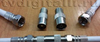
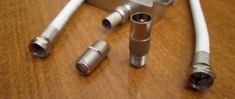
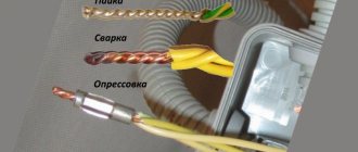
If you need to connect an antenna cable without loss of signal, the only correct method is to install two F-connectors at the ends and connect them with a threaded adapter. This is the most reliable way, and you can always disconnect back if necessary.
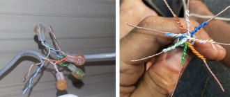
If we talk about twisting, then this is the worst way to connect a television cable to each other. A high-quality alternative is soldering, which also eliminates the loss of the television signal after connection.
Cable preparation. Video
The video below will tell you how to prepare a TV or satellite antenna cable for use.
You can extend and branch a television cable with your own hands if you follow the rules described in the article.
To watch over-the-air TV channels, in addition to choosing a suitable antenna, you need to connect it correctly. Let's figure out how to do this correctly, what to pay special attention to, and how to avoid possible problems that you might not have guessed about.
How to connect: working methods
- Adapter for connecting two F-type connectors to each other (coupling coupling). In common parlance it is called a barrel. The screen is connected through the common metal part of the adapter. And inside there is a groove for connecting the cable core. This is the best way to connect or extend a TV cable.
- Soldering. The second best method of attaching wires. But you need to know how to use a soldering iron. Therefore, you need a soldering iron and solder.
- Twisting. Allows you to return the line to functionality, but is not recommended for use. It is better to use it only as a temporary connection until you buy an adapter.
- Extension cord for television cable. Sold immediately with plugs attached. A female connector is attached to one side to connect it to the male end of the previous wire. If you need to do cable extension, then this is a good option. There is nothing you need to do other than plug in the extension cord. The cost of the cord depends on the length and quality of workmanship (conductor material and insulation).
- Splitter. If in a home television system only one TV operates from the antenna, then installing even the simplest two-channel splitter is not worth it. Yes, the divider contains one antenna signal input and outputs. Therefore, connect one part of the wire that leads from the on-air receiver to the input of the splitter, and connect the second to the output. But the problem is that the splitter not only passes the signal through the connected cable, but also splits it. The division is performed by the number of outputs on the splitter. Therefore, if one TV receiver is used, then initially the maximum signal will be halved. This may affect the reception of television channels. So, if the already weak signal level decreases by half, then half of the channels may disappear. That is, the TV will show 10 channels, not 20. This is a fairly common situation with people who connect through a television divider.
Cable device
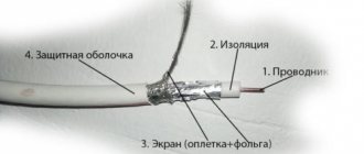
In the center of the core there is a central copper conductor with a diameter of 0.3 to 1.1 mm (signal wire). It is not recommended to take a smaller size, since it is designed for the frequency of the meter range. Through a thin cable, the TV will only show the main channels. It is better for the user to choose a thicker cable that has less signal loss.
On top there is a shielding layer of aluminum foil and a braid of thin copper wire, which protects against external interference in the form of electromagnetic waves. Between the central wire and the screen there is a layer of polyurethane insulation. Outside there is another insulation made of polyvinyl chloride or polyethylene to protect the cable from mechanical stress and ultraviolet radiation.
The cable must have foil and braid as a screen. Old-style products with a single braid are not suitable for modern video signal transmission standards.
The centers of the wire and the screen coincide in the radial direction. Due to this, losses of the transmitted signal are reduced.
Coaxial cables differ in the following parameters:
- outer diameter (best sizes - 6-8 mm);
- wave resistance;
- degree of shielding;
- flexibility.
The markings of common television cables are as follows:
- imported – RG-6, RG-59;
- domestic - RK-75 (75 Ohm - the value of wave impedance).
It is not recommended to purchase the RK-75 cable, as it has a high signal attenuation rate. In city conditions, this may not be noticed due to the close proximity of transmitting stations, but in rural areas, signal loss becomes noticeable.
When laying a television cable near electrical wiring, its diameter must be at least 10 mm and have increased protection against interference.
When choosing a cable, you should pay attention that it is not too flexible. The braid should be chosen more densely. Too rare - it easily misses interference. The foil should not be very thin.
The insulation of the central core should be hard, not soft like foam rubber.
When studying the passport data, attention should be paid to the frequency and amount of attenuation of the television signal at a certain length. The lower they are, the higher the quality of the cable.
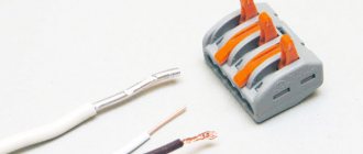
How to make the connection correctly
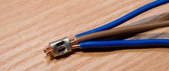
Before connecting a TV cable without causing loss of the antenna signal, it is necessary to install F-type connectors on the two ends being connected. The action is quite simple, even beginners can handle it. To work you need a sharp knife, the connector itself and pliers.
- First, the cable sheath is removed from the edge by 1 cm.
- The screen straightens and bends in the opposite direction (inward).
- The vein is exposed. To do this, 7-8 mm of the inner layer is removed from the previously cleaned area.
When the cable for the F-connector is cut, installation is done. Start winding the part onto the wire with your hands. If installation is difficult, use pliers to help. But you don’t need to clamp it too hard, as this can lead to breakage of the connector housing. Modern parts are made of thin metal of poor quality.
Also mount the antenna connector on the end of the second TV cable.
Afterwards, complete the connection by screwing the connectors onto the barrel.
If you need to connect three cables, then not a double, but a triple coupling is used. The principle of operation is similar, only three wires are processed.
Connecting the antenna to the TV
Typically, the antenna jack is located on the back of the TV and is labeled “ANT”, “ANT IN” or similar. But the easiest way to identify this nest is visually. It is characterized by the following symptoms:
- ring-shaped metal edging;
- the central groove is a convexity with a hole into which either the central core itself or a protrusion inside the plug fits.
The antenna jack differs from other connectors in shape. It is physically impossible to connect anything other than the plug itself.
If the TV can receive both terrestrial and satellite signals of the DVB-S standard, it has two antenna connectors. The one intended for the satellite signal is marked as “ANT SAT”, “ANT 2 IN SATELLITE”, etc. The satellite antenna socket also has a notch in the center, but usually has an external thread for screwing the plug onto it.
Solder connection
You can take the easiest route and solder without any problems. Simply expose the conductive parts of the wire (shielding layer and copper core). Next, solder the wire and rewind it with electrical tape. Then do the same with the braid, cover with insulating tape. The option is working, but unprofessional.
Soldering can be done much more accurately, maintaining maximum joint quality. First, text instructions are provided, and then a step-by-step gallery of pictures is located.
- Make a longitudinal cut of the shell to a length of 50-60 mm.
- Bend the shell along with the entire shielding layer back.
- Cut about 20 mm of internal insulation from the conductor. The shortening is done so that after joining the core for connecting the screen there is a reserve.
- Position the cables so that the sides of the outer cuts face each other. From the inside, half expose the core by making a transverse cut of 20 mm.
- Bend the insulation away from the core to make it easier to work further.
- Solder the wires together along all available lengths.
- Align the core so that it is flush with the rest of the wire. The insulation halves must fit together. If there are any excess pieces left on top, cut them off with a knife.
- Then connect the foil and solder the braid. The inside of the foil does not conduct current, so when the top foil layer is placed on the bottom, there may be no contact. Therefore, you need to unfold the top or bottom layer so that the top of the foil of one wire is in contact with the top of the other.
- At the last stage, return the previously cut shell to its place and rewind with electrical tape.
Antenna cable assembly
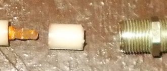
The F-plug is mounted on the cable as follows:
- Take the connecting end and carefully remove it from the outer insulation at a distance of about 1 cm from the edge.
- Carefully wrap the exposed braid and foil screen back onto the part of the cable where the outer sheath is still intact.
- Cut and remove the freed portion of the inner insulation to expose the center core.
- Screw the F-plug onto the wrapped braid.
- Cut the central core with wire cutters so that about 2–3 mm of wire remains sticking out.
- Screw the second part, the adapter, onto the half of the plug that has already been put on the cable until it stops. This is not a required component, but using a “dual-layer” plug improves contact between the wire and the equipment.
Twist
The connection cannot be used for dissimilar materials, for example, copper and steel, or aluminum and copper. In the future, this will lead to oxidation and, as a result, contact breakdown.
The operating technology is very simple:
- perform stripping;
- Twist the wires, wrap them with high-quality electrical tape in several layers;
- twist the screens and also wrap them with insulation on top.
This can be done using the same algorithm as soldering (see above).
Connecting the cable to an individual antenna
Depending on the connection method, individual antennas are of two types:
- The cable and plug are attached by the manufacturer. As a rule, these are indoor antennas with a short wire length;
- You must connect the cable yourself.
In the latter case, the procedure looks like this:
- The top insulation is removed from the cable, the braid is wrapped back;
- the insulation is removed from the central core. Dimensions depend on the connection socket on the antenna;
- the core is inserted into the screw connection and clamped there using a screwdriver;
- the braid together with the cable is pressed against the second terminal.
Connection via a splitter
Twisting three or more cables together is not the best solution. If you need to watch more than one TV receiver from one terrestrial DVB-T2 antenna, you should connect through a splitter.
To connect, use the instructions above about using a coupling (adapter). The splitter uses threads of the same diameter, so the connection principle is no different.
The only thing is that the nests must match. The crab's input is signed IN, ANT IN. This is the input for connecting the cable that leads from the antenna. Each output is signed OUT with a number. There can be up to 8 of the latter on one device. The quantity depends on the splitter.
If the antenna is active, then the same divider is needed. The ability to pass power from an external unit or set-top box through a splitter is required. Typically the divider will have a "Power Pass" designation on it.
Cable selection
To connect the antenna to a TV or digital set-top box, a coaxial cable with a resistance of 75 Ohms is required. There are many brands from different manufacturers on the market. Which to choose?
Start with the core type.
To transmit a TV signal from an antenna to a TV receiver, cables are used in which the central core is made:
- Made from pure copper. Used for satellite television systems: the signal transmitted from space has extremely low power, and any losses are inappropriate here. Copper has very low resistance.
- With copper plating. The central core is steel, but covered on top with a thin layer of copper. Such cables are used for terrestrial television systems: signal loss is greater, but not critical, and copper-plated steel costs almost 2 times less.
When choosing a cable, it is important to consider:
- Type of signal being transmitted. “Brand” brands of cables are best used for satellite TV antennas. For broadcasting or cable wiring, simple domestic ones are sufficient.
- Length of the route. Even “premium” brands have internal resistance, and the longer the signal path, the greater the loss. At distances up to 5 m, this can be neglected, but when connecting an external antenna on a high mast, the distance will affect it.
- The thickness of the central core. Standard cables have a core 1 mm thick. There are also thinner cords with a half-millimeter core. They are more convenient to install, but they are more difficult to connect to devices, and resistance losses are often higher.
- Possible obstacles on the installation path. If there are sources of interference nearby (alarm lines, electrical wiring, etc.), it is better to buy an option with maximum shielding.
- Outer shell material. The cable is insulated from the outside using black PVC or white polyethylene. The difference indoors is small, but for outdoor work craftsmen recommend more reliable PVC.
Among the brands of cables used for television antennas, the most popular are the following:
- RG 6. Product of joint Russian-Chinese production. Inexpensive, but high-quality, shielded, with a 1 mm central core made of steel or copper, aluminum braid and PVC sheath.
- RK 75. A purely Russian analogue of RG 6, produced since Soviet times. It has a copper central core with a diameter of 1 mm, a copper braid or a double screen made of tinned copper and aluminum lavsan. Can be used both for broadcasting terrestrial or cable TV, and for connecting satellite antennas (with a double screen).
- RG 59. Thin and light cable with a 0.5 mm core. It is universal, but due to the high resistance of the wires it is unsuitable for transmitting a signal over a distance of more than 200 m.
- SAT 50. Italian, with a millimeter core and a two-layer reinforced braid of copper and tin. It has a high shielding coefficient - up to 60 dB.
TV extension cord
If you just need a small amount of cable, and you don’t want to do it yourself, the question is how to make the TV cable reach the equipment, you can use an extension cord.
Read here - Do-it-yourself kettle repair: principle of operation, design, main types of malfunctions. Step-by-step photo repair instructions. Prevention of breakdowns
There are many different types of extension cords. You can find ones up to 20 m long, but their price is many times higher than the cost of coaxial cable.
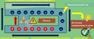
Features of coaxial TV conductor design
In a power cable, the potential moves throughout the entire volume of the conductor, and the strip potential tends to the surface of the wire. The more often he repeats it, the faster he moves closer to her. Penetrating into the body of the conductor, the amplitude of oscillations of electromagnetic waves decreases. The amount of signal attenuation can be determined only after connecting the signal receiving and transmitting cable.
Product components:
- main copper, copper-plated steel conductor;
- impermeable shell;
- aluminum foil, which serves as a secondary material that conducts electric current;
- a screen that counteracts electromagnetic fields;
- plastic external insulation that protects the contents from external influences and atmospheric phenomena.
A selected product consisting of several insulated conductors, coated optical fibers, must be connected to the TV. The simplicity of the operation and its safety make it possible for each owner of a television device to independently decide how to connect the antenna cable to the plug. Low, microvolt voltage allows you to cut the cable without disconnecting its second end from the TV. Electrical contact of network points does not create a danger as a result of contact between the conductor and the interlacing of metal strands protecting the contents.
An entertainment and information unit is connected to a multilayer cord by connecting the latter to the F-connector.
Before connecting, check the quality of the wire used.
Selection conditions:
- familiarize yourself with the special barcode attached to the product shell indicating its characteristics and properties. It is preferable to choose a copper or copper-plated steel core located in the center, which is an excellent medium for the passage of electric current and counteracts temperature changes;
- choose a rigid shell that will not break when bent. Rubber has a short lifespan;
- take into account the density of the existing braid. The insulation screen affects full-color, digital image and sound transmission, and performs various functions: protective, insulating, transit.
Calculate the cable length and indicate the operating frequency of television channels to check the level of signal attenuation (the lower it is, the better the device works). An indicator of 70% indicates the end of the service life of the insulated cord.