In everyday life, we often encounter problems that do not require calling a specialist to solve. Why pay for work that you can do yourself with a minimum of effort, right?
If for some reason the antenna cable's plug connecting it to the TV receiver's socket has fallen off, you can return the part to its place on your own in just a few minutes. But to do this you need to know the rules for cutting the cable and the procedure.
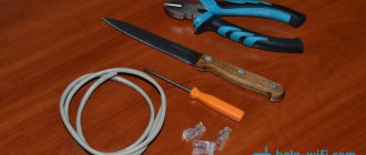
Let's take a closer look at how to connect the antenna cable to the plug using the only available tool - a stationery or construction knife. And at the same time, we’ll find out what an amplifier is and whether it’s possible to make the wiring for two TVs yourself.
Connection errors
I’ll probably start by citing the most common mistakes when connecting a cable. When installing the plug, you must immediately pay attention to this in order to eliminate troubleshooting in the future.
- The inner side of the foil does not conduct electric current; it is the base on which aluminum is sprayed. When you wrap it over the braid, there will be no contact with the F-connector. Therefore, it is better to remove it or turn it back.
- When wrapping the braid, you should pay attention that all the cores of the braid are removed and cannot touch the central core, as this leads to a short circuit. In this case, if the set-top box does not have protection against short circuits in the cable, this may lead to its failure.
- When crimping some types of plugs, you should not do this too much as this can also lead to a short circuit between the central core and the screen (braid).
Connecting the antenna to the TV
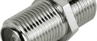
To properly connect the antenna to the TV, it is better to use special plugs. Currently, so-called F-connectors (or F-connectors) have become widespread. They are installed directly on a coaxial cable with a diameter of 6.8 mm with a characteristic impedance of 75 Ohms intended for television equipment.
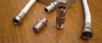
With this type of connector, additional attachments can be used: male and female plugs, angled plugs, cable connectors. The variety of such antenna adapters for TV is very large. The advantage of this connection is obvious; it makes it possible to connect a cable without soldering using one knife in a few minutes anywhere. This ensures the reliability of the connection against mechanical stress.
Rusty cable connection contacts
Unfortunately, there are enough counterfeits on the market and you can buy copies like these. This means that the connector was exposed to a damp environment and simply rusted. Most likely the insides of such a connector are made of iron rather than bronze or brass. In this case, signal jumps, insufficient signal levels, or even loss will be observed.
Of course, you can connect an antenna to a TV without a plug; just make contact between the RF connector of the TV and the cable. The braid is connected to the connector body and the central core must fit into the central part. Of course, such a connection is not reliable and it is better to solder it, but there is a possibility of damaging the RF contact of the TV.
Fiber optic adhesive connectors with crimping
Proper crimping of a fiber optic connector ensures that the tensile force is transferred to the connector and not to the fiberglass. The crimping process involves the body of the optical connector, a metal crimp sleeve, and an aramid filament (also known as Kevlar®), which is the cable's strengthening element. Crimping crimpers are divided into two main types: the first - for FC, SC, ST connectors and the second - for LC connectors.
Adhesive optical connectors for crimping
Crimp profile
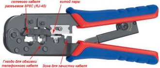
Tool for crimping optical connectors (crimpers and press pliers)
Connecting the cable to the plug
F - male connector
In order to immediately correctly connect the antenna cable to the plug without any modifications, it is enough to follow certain dimensions and sequence of actions, but do not be afraid that you may get an electric shock, since the voltage in the cable is very low. So, to properly strip the TV cable you need:
- at a distance of 12 - 15 mm, make an incision in the outer shell so as not to damage the braid and, tilting it to the sides, break it off and pull it off (you can do this in a way convenient for you);
- wrap the braid;
- when folding the foil, keep in mind that its inner layer does not conduct current, so turn it around the axis again with the outer layer up or remove it altogether;
- cut the dielectric of the central core at a distance of 8 -10 mm from the end and remove it;
- screw the F connector onto the cable;
- screw the plug into the connector.
If the central core protrudes more than 4 mm, it may rest inside the connector and prevent the nut from screwing in completely, so remove the excess.
If the cable diameter is small, you can wrap a little electrical tape and then wrap the braid on it.
Crimp plug
In this case, the central core is clamped with a screw, and the braid is crimped by the plug body:
- a protective casing is put on the cable;
- the outer shell is stripped to 10 mm;
- aluminum foil is removed;
- the insulation of the central core is removed by 3 mm;
- the braid is wound onto the remaining dielectric;
- the central core is inserted into the groove and clamped with a screw;
- the braid is crimped onto the plug body;
- We screw the protective casing onto the body.
Connecting the antenna power supply separator
In this case, when connecting the cable to the power supply, the dimensions change slightly:
Correctly connect the power supply to the antenna
- the outer protective shell is stripped to 15 mm;
- the foil is removed;
- the braid moves towards the protective sheath;
- the dielectric of the central core is removed by 5 mm;
- the cable fastening screws in the separator are loosened;
- The cable is inserted into the resulting openings and clamped with screws.
Be careful when clamping the braid: firstly, it must touch the tinned area on the board; secondly, make sure that the braid does not touch the central core.
To watch over-the-air TV channels, in addition to choosing a suitable antenna, you need to connect it correctly. Let's figure out how to do this correctly, what to pay special attention to, and how to avoid possible problems that you might not have guessed about.
Straight cable 4 conductors
In LANs transmitting data at speeds of 100 mbit/s - 10 gbit/s (Ethernet specifications 100BASE-TX, 1000BASE-T, 10GBASE-T) all eight cores are used, and in slower ones - 10-100 mbit/s (10BASE specifications -T, 100BASE-T) – only four: 1st, 2nd, 6th, 3rd.
Straight crimp with 4 wires
The crimping circuit for a twisted pair of 4 wires can use twists of different colors, but usually red and green. However, if you use blue and brown instead, the patch cord will work just as well.
The remaining wires can be useful when repairing the cable if a break or short circuit occurs in one of the involved strands. Instead of replacing the entire patch cord, it is enough to re-crimp both ends, connecting the free cores instead of the damaged ones.
Crossover (crossover) patch cord 8 conductors
A twisted pair cross-crimping circuit of 8 wires is used when connecting two computers or concentrators (hubs). Today it is rarely used, since all network equipment released after 2004-2005 can automatically detect the cable type and “cross” the signal inside the port (auto-MDIX technology). However, many LANs still have outdated devices that do not support auto-MDIX, so it is imperative to know the cross-crimping procedure for the cable.
The twisted pair cross-crimping circuit, like the straight-crimping circuit, can be type A or B.
Option B for high-speed networks (100 mbit/s – 10 gbit/s) or, as it is called, Gigabit Crossover looks like this:
Cross crimp with 8 cores
| Pin | Connector 1 | Connector 2 |
| 1 | R.B. | B.Z. |
| 2 | R. | Z. |
| 3 | B.Z. | R.B. |
| 4 | G. | K.B. |
| 5 | B.G. | TO. |
| 6 | Z. | R. |
| 7 | K.B. | G. |
| 8 | TO. | B.G. |
When transmitting data in networks of this type, all eight wires are used, and through each of them the signal is transmitted in both directions.
Option A differs from B in the position of the 1st, 2nd, 6th and 3rd cores (green-white exchange places with orange-white, green with orange). Patch cords, crimped according to standards A and B, are interchangeable; there is also no specific order for connecting them to devices (either end - to either end).
In a LAN with a lower bandwidth (10-100 mbit/s), blue and brown twists are connected without crossing.
The figure shows standard B:
Cable cross crimp
| Pin | Connector 1 | Connector 2 |
| 1 | RB. | BZ. |
| 2 | R. | Z. |
| 3 | BZ. | RB. |
| 4 | G. | G. |
| 5 | BG. | BG. |
| 6 | Z. | R. |
| 7 | KB. | KB. |
| 8 | TO. | TO. |
It is inappropriate to talk about standard A in this case, since it is a mirror image of the above table.
Cross Patch Cord 4 Conductors
In the crossover crimping circuit of a twisted pair of 4 wires, two twists of any colors are used, which intersect, for example, in this order:
1 pin – white-blue – red-white; 2 pins – blue – red; 3 pin – like the first, but in reverse; 6 pins – like the second one, but in reverse.
Crossover crimp, 4 cores
The choice of color, as with direct crimping, does not affect anything.
Installing two connectors on one patch cord
Using one eight-core cable, you can connect 2 computers to the network at once, if you allocate 4 wires or 2 twists for each. Data over such a connection will be transmitted at speeds of up to 100 mbit/s, which is quite enough for lightly loaded home or office LANs.
The crimping scheme for an RJ 45 twisted pair depends on what is connected to what - a computer with a network device or 2 PCs between each other. In the first case it will be straight, in the second – cross.
Conclusion
After reading this article, you have taken a big step towards independent network building.
After mastering the rules for crimping patch cords, you can move on to practice. Read on to learn how this is done using crimping tools, as well as improvised tools (screwdrivers).
Cable selection
To connect the antenna to a TV or digital set-top box, a coaxial cable with a resistance of 75 Ohms is required. There are many brands from different manufacturers on the market. Which to choose?
Start with the core type.
To transmit a TV signal from an antenna to a TV receiver, cables are used in which the central core is made:
- Made from pure copper. Used for satellite television systems: the signal transmitted from space has extremely low power, and any losses are inappropriate here. Copper has very low resistance.
- With copper plating. The central core is steel, but covered on top with a thin layer of copper. Such cables are used for terrestrial television systems: signal loss is greater, but not critical, and copper-plated steel costs almost 2 times less.
When choosing a cable, it is important to consider:
- Type of signal being transmitted. “Brand” brands of cables are best used for satellite TV antennas. For broadcasting or cable wiring, simple domestic ones are sufficient.
- Length of the route. Even “premium” brands have internal resistance, and the longer the signal path, the greater the loss. At distances up to 5 m, this can be neglected, but when connecting an external antenna on a high mast, the distance will affect it.
- The thickness of the central core. Standard cables have a core 1 mm thick. There are also thinner cords with a half-millimeter core. They are more convenient to install, but they are more difficult to connect to devices, and resistance losses are often higher.
- Possible obstacles on the installation path. If there are sources of interference nearby (alarm lines, electrical wiring, etc.), it is better to buy an option with maximum shielding.
- Outer shell material. The cable is insulated from the outside using black PVC or white polyethylene. The difference indoors is small, but for outdoor work craftsmen recommend more reliable PVC.
Among the brands of cables used for television antennas, the most popular are the following:
- RG 6. Product of joint Russian-Chinese production. Inexpensive, but high-quality, shielded, with a 1 mm central core made of steel or copper, aluminum braid and PVC sheath.
- RK 75. A purely Russian analogue of RG 6, produced since Soviet times. It has a copper central core with a diameter of 1 mm, a copper braid or a double screen made of tinned copper and aluminum lavsan. Can be used both for broadcasting terrestrial or cable TV, and for connecting satellite antennas (with a double screen).
- RG 59. Thin and light cable with a 0.5 mm core. It is universal, but due to the high resistance of the wires it is unsuitable for transmitting a signal over a distance of more than 200 m.
- SAT 50. Italian, with a millimeter core and a two-layer reinforced braid of copper and tin. It has a high shielding coefficient - up to 60 dB.
Device
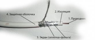
The coaxial cable contains a screen (3) separated by an insulating layer with a central conductor (1), located coaxially (Fig. below). The cable is covered on top with a protective sheath (4). Between the central conductor and the screen there is a dielectric layer (2), the technical characteristics of which largely determine the quality of the transmitted video signals.
Coaxial cable device
The video signal is transmitted through a center conductor, which is made of copper or copper-plated steel. The magnitude of its resistance is determined by the material and cross-sectional size. A wire with a steel core significantly increases the circuit resistance and cannot be used in television surveillance systems.
When choosing a cable, you need to carefully inspect it. Steel can be seen by its characteristic silver color. The diameter of the core should be chosen larger, since it has less active resistance. It transmits the signal further and of better quality. The price of such a cable is higher and it is more rigid. If you need a cable with greater flexibility, choose a central wire woven from thinner ones. In terms of characteristics, it is slightly inferior to a single-core cable.
The central conductor and the braid are separated by polyethylene insulation. Polyurethane, polyethylene foam or non-flammable polymer material containing fluorine are also used. Foamed dielectric reduces video signal loss, but it absorbs moisture better and is not recommended for use in a humid environment.
Solid polyethylene increases the rigidity of the cable, but is more resistant to mechanical stress. It is more difficult to lay it, and the characteristics are somewhat worse. If the dielectric is chemically foamed, its resistance to temperature and moisture, as well as to mechanical damage, is reduced. When the compound is foamed physically, it has the same strength and resistance to environmental influences as solid polyethylene, and its parameters are much better.
The copper braid shields from interference and acts as a second grounding conductor. The denser and thicker it is, the greater the quality of shielding. Liquid braid is only suitable where there is little interference, under normal application conditions. It is also suitable for cables laid in metal ducts or pipes.
For unknown application conditions, the cable with the greatest protection against external influences should be selected. If the characteristics cannot be determined, a cable with the highest density braid and copper conductor of the television signal is selected. A modern television cable contains non-ferrous metal foil along with braiding (Fig. below).
Double Screen TV Cable
The result is a shielding effect of up to 100%, although the cost and weight become higher. If only foil is used for the screen, the cable is not suitable for television systems.
External polyvinyl chloride (PVC) insulation protects internal components from the elements. The difference from a conventional wire with a screen is the higher quality of materials and standardized characteristics.
Cables should be selected according to their characteristics so that the resolution allows them to be used. For example, RG-59 and PK-75-4 cables can transmit a signal over 300 m, and RG-11 and PK-75-7 cables can transmit a signal over 500 m. At the same time, long cable lengths are more affected by external interference and also increase attenuation signal. As the length increases, the brightness first decreases, then blurry pixels appear, and the image on the screen begins to double.
To reduce signal loss, you should use a cable with a larger diameter (it is indicated on the marking after the number 75).
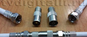
Antenna plug selection
When you have selected the desired option, connect the antenna cable correctly. You can do this in the following ways:
- Soldering. Only suitable for installing homemade TV antennas. We don't recommend it.
- F-plug. Suitable for connecting antennas for both digital and analogue television. Structurally, it is a washer that is screwed onto the end of the cable, where the outer insulation has been stripped and the braid and screen have been bent. The plug crimps the bent shielding elements, and the exposed central core is connected to the signal slot. We recommend!
- Old style plug. They were produced back in Soviet times. It differs from the F-plug in that it requires complete disassembly for installation. It has greater rigidity, and when assembled correctly, the strength is higher than modern ones. It is permissible to use.
City Antenna Service
- Moscow antenna service
- TV antenna repair
- TV cable installation
- TV cable wiring
- Receiver repair
- Connection
- Antennas for TV
- TV antenna
- TV cable
- Pad
- Antenna cable
- TV cable
- Wiring
- Antennas
- Television
TV cable laying
Laying a television cable can be done in different ways. There are the following types of such work:
A non-hidden (open) method of laying, as a rule, simply on top of the baseboard. And hidden laying under the baseboard or inside it, as well as the option of laying the television cable in grooves. Also in a special cable channel, which is a decorative groove with a lid.
An open (not disguised) option for laying a television cable is on top of the baseboard. This type of laying involves the usual pulling of the cable through the rooms along the walls, and so that it does not dangle, it is secured with special brackets. This is the simplest and cheapest way to lay a cable, but it is not always so simple. Sometimes you have to lay it through the walls, and carry out some of its distances inside the door frames. The undisguised method does not look very presentable, but it is cheap to implement and quick to use.
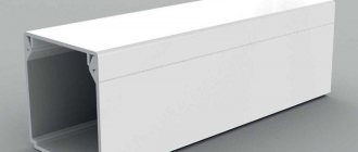
Using cable channel.
Today, the market for modern building materials offers many different cable channel solutions. Basically, they are different forms of decorative plastic grooves with a lid. They can be of any colors and sizes. You can choose the most suitable box for the overall decor of the rooms. Usually it is neatly mounted to the wall near the floor. Its advantages are that you can always lay some other wires in it, for example, telephone or Internet. Installation of such a channel is one of the optimal solutions to the problem of laying a television cable in a city apartment. You choose the material yourself.
Hidden installation of the television cable inside, or under the baseboard (wall).
Unlike the previous option, this installation method differs in that the cable is laid in a special plinth. This disguises your television wire. The technician, examining the apartment together with you, determines how and where the installation of your television cable will take place and determines its method, and also informs about the cost of services.
Antenna cable assembly
The F-plug is mounted on the cable as follows:
- Take the connecting end and carefully remove it from the outer insulation at a distance of about 1 cm from the edge.
- Carefully wrap the exposed braid and foil screen back onto the part of the cable where the outer sheath is still intact.
- Cut and remove the freed portion of the inner insulation to expose the center core.
- Screw the F-plug onto the wrapped braid.
- Cut the central core with wire cutters so that about 2–3 mm of wire remains sticking out.
- Screw the second part, the adapter, onto the half of the plug that has already been put on the cable until it stops. This is not a required component, but using a “dual-layer” plug improves contact between the wire and the equipment.
If you need to connect an old-style plug to a cable, the process depends on its design.
But most often it looks like this:
- Disassemble the plug by unscrewing the metal contact from the plastic housing.
- Immediately put the unscrewed housing on the cable - this makes it easier to continue working.
- Cut off about 1 cm of the outer sheath of the wire, remove the insulation.
- Carefully trim the shielding braid by 4–5 mm.
- At the place where the braid was cut, carefully strip off the inner insulation so that the central core is exposed.
- Insert the central core into the socket of the metal part of the plug. Using pliers, gently but firmly squeeze the petals around the exposed shielding shell. Here you need to make sure that the braid does not touch the central core.
- Screw in the center core fixing screw.
- Screw the plastic shell onto the metal part. The plug is ready.
Another option is soldering. The process is shown in the photographs.
The described procedures relate to preparing the cable for the antenna socket of the TV receiver. However, if the TV is connected via a set-top box, the procedure for installing the plug will be identical.
Laying TV cable, Calling a technician - Moscow and Moscow Region
We will quickly and efficiently install a TV cable in the apartment from the switchboard, and lay the cable to all TVs.
Our craftsmen lay the television cable from the panel to the TV, as well as install the antenna cable to the TVs that are available. If necessary, we carry out repair or replacement of TV cables. We have extensive experience in installing antenna cables, which ensures quality and high efficiency of work.
Need a cable for your TV? Call us!
Our specialists will find the best solution for your needs and personal preferences. To install high-quality TV cables, we use our technical knowledge and experience. If you want to connect your TV cable, call TV-COMFORT today.
Call an antenna cable technician if you need:
- Wiring a TV cable from a low-current panel to the apartment;
- Pulling the antenna cable to the TV in a cable channel, boxes;
- TV cable installation and creation of additional TV points;
- Connecting a TV cable and setting up the TV.
Need TV cable installation? Call tel. – we will arrive at a time convenient for you!
Prices for laying television cable
The cost of laying an antenna cable from the switchboard around the apartment to the TV - Price: from 2000 rubles.
The television cable is connected to the distribution box in the switchboard on the landing. You can connect the TV to the communal TV antenna in the apartment directly through the TV cable plug or through the TV socket.
| Connecting a television cable to the main switchboard on the landing | from 1,000 rub. |
| Wiring a TV cable from the control room from the landing to one TV (without consumables) | from 2,000 rub. |
| Run a television cable from the panel to two televisions (without consumables) | from 3,000 rub. |
| Run a TV cable from the panel to three TVs (without consumables) | from 4,000 rub. |
| Lay a TV cable to four or more TVs (without consumables) | from 1,200 rub./point |
| Installing a crab (splitter) | from 250 rub. |
| Setting up your TV (sorting channels) | 500 rub. |
| Antenna amplifier installation | from 500 rub. |
View all prices »
The cost of TV cable wiring does not include:
- Installation of the antenna cable in a plastic plinth, in the trim of interior doors;
- Pulling television cables through technological holes and corrugated cable ducts;
- Drilling and drilling holes for television cables in walls.
If the baseboards do not have a special channel for running the TV cable, then the TV cable is attached to mounting brackets.
Do you want to run an antenna cable from the switchboard to the TV, get advice or call an antenna specialist to your home? Call tel.
Methods for laying television cable
It is also necessary to take into account the fact that laying a television cable requires its insulation in baseboards and cable ducts, or, in their absence, in places where it will be less noticeable. Will a non-professional be able to take into account all these nuances? The answer is obvious: of course not.
We employ only experienced, qualified specialists who will perform any work related to laying the antenna cable with maximum quality, accuracy and speed. In our range of services, we offer open and closed wiring, connecting a TV cable in a panel, connecting a TV cable to a TV. We carry out this work in buildings of various types and purposes.
TV cable is laid in the apartment and other premises in the following ways:
- open - in this case, the cable is laid directly on top of the baseboard;
- closed laying of television cable.
The closed method involves hidden wiring of the TV cable, which in turn can occur in two ways:
- inside the baseboard. This option allows you to best disguise the installation of the antenna cable under the surface of the baseboard in special cable channels;
- inside a special decorative box. This method is also convenient; it will help hide the cable and other wires in the apartment. Typically, such boxes are attached closer to the floor and do not affect the decor of the room.
The closed method of wiring the antenna cable is more expensive, but will not affect the appearance of your apartment in any way.
Our antenna technician will help you choose the optimal method for installing a TV cable after inspecting the premises.
Types of television cable
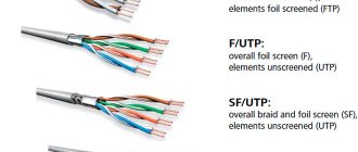
The main cables used to transmit a signal from a source to a TV are coaxial. Such a wire consists of a central copper core with surrounding insulation, a metal braid (screen) and a durable outer sheath. In addition to the screen, modern cable models also have a foil layer, which provides better signal protection from interference.
Coaxial cables can be of two types:
- thin. This type is very durable and flexible, the signal transmission bearing capacity is up to 190 meters;
- thick TV cables. They can be up to 2 cm in diameter, are inelastic and more difficult to work with. Signal capacity is higher – up to 500 m.
Only a specialist can tell you which option is best for installing a TV cable in your apartment.
The choice of TV cable wiring method at each site is made individually after inspection by our specialist.
Our company has sufficient experience in providing services for laying TV cables, which will ensure a high-quality result of the work and a long service life. We work only with proven equipment and provide guarantees for the services provided.
We are fully responsible for the quality of our work, therefore we provide the entire range of warranty and post-warranty services.
Order TV cable installation at a competitive price! Call tel.
Connecting the antenna to the TV
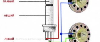
Typically, the antenna jack is located on the back of the TV and is labeled “ANT”, “ANT IN” or similar. But the easiest way to identify this nest is visually. It is characterized by the following symptoms:
- ring-shaped metal edging;
- the central groove is a convexity with a hole into which either the central core itself or a protrusion inside the plug fits.
The antenna jack differs from other connectors in shape. It is physically impossible to connect anything other than the plug itself.
If the TV can receive both terrestrial and satellite signals of the DVB-S standard, it has two antenna connectors. The one intended for the satellite signal is marked as “ANT SAT”, “ANT 2 IN SATELLITE”, etc. The satellite antenna socket also has a notch in the center, but usually has an external thread for screwing the plug onto it.
Temporary connection of an antenna cable without a plug
If you urgently need to connect the antenna, but there is no plug at hand, you can do without it for a while.
A quick connection is done like this:
- the top insulation approximately 5 cm long is removed from the cable;
- the shielding braid is bent back;
- the central core is stripped of insulation and bent into a loop slightly wider than the diameter of the hole in the center of the antenna connector;
- a dielectric tube is put on the central contact (for example, from the removed insulation from the central core);
- the loop is inserted into the central contact, the braid is tucked into the connector using a screwdriver. The main thing here is to prevent contact between the central core and the shielding braid;
- if aluminum braiding is used, then it is simply inserted into the connector, and the free space is filled with small wires;
- to prevent the cable from falling out, it is tightened with a pair of sharpened matches;
- If contact has been achieved, the TV will begin to receive a signal from the antenna.
Connecting the cable to an individual antenna
Depending on the connection method, individual antennas are of two types:
- The cable and plug are attached by the manufacturer. As a rule, these are indoor antennas with a short wire length;
- You must connect the cable yourself.
In the latter case, the procedure looks like this:
- The top insulation is removed from the cable, the braid is wrapped back;
- the insulation is removed from the central core. Dimensions depend on the connection socket on the antenna;
- the core is inserted into the screw connection and clamped there using a screwdriver;
- the braid together with the cable is pressed against the second terminal.
How to connect several TVs to 1 antenna
If you need to connect several TV receivers to one antenna, you will need cable routing devices - splitters or splitters. In the simplest case, the connection will look like this:
- The coaxial cable coming from the antenna is stripped, an F-plug is put on it, and it is connected to the input jack of the splitter.
- Wires for TVs are prepared and inserted into the output sockets using connectors.
If the signal is taken from an active antenna, you need a splitter with a power pass or connecting an external power supply antenna amplifier in front of the splitter.
Depending on the model, splitters can have from 2 to 8 outputs. If more TVs are connected, you need to calculate and build a chain of new splitters and signal amplifiers.
Antenna amplifier: in what cases is it needed?
In order for the digital tuner of a TV or receiver to extract information from the signal received from the antenna, it must have sufficient power.
To correct this situation, you just need an amplifier. The device is connected in the area between the antenna and the TV and increases the signal strength.
An amplifier is needed in the following situations:
- reception is carried out using a passive antenna;
- it is not possible to use power from an active antenna (for example, the signal to TVs goes through a regular splitter);
- The reception conditions are such that the signal received from the antenna is too weak. This happens due to distance, interference, obstacles in the signal path, etc.
What you need to connect
Regardless of the type of connector, you cannot do without a cable. For our purposes, we will need a coaxial cable with a resistance of 75 Ohms, preferably the following brands:
These types of cable are suitable for outdoor and indoor installation. The specified marking is applied on the side surface of the braid, along with an indication of the manufacturer, product quality, wave resistance and meterage mark. The TV, splitters and amplifiers are designed for a resistance of 75 Ohms, so this parameter is fundamentally important.
You will also need a plug to connect to the TV. Its installation does not require any special skills or permission to work with high voltages - electric shock from the antenna cable is excluded, since it uses high-frequency currents of very low voltage.
Connection instructions
Most modern television equipment provides for the connection of a so-called F-plug. There are three main sizes of plugs, depending on the cable cross-section. Before purchasing, you should make sure that the components you purchase are compatible.
There are two ways of wrapping - with and without a fold of the shielding braid. The first method is more reliable, but the second is used if the plug cannot be screwed over the braid.
The first step is to carefully remove the top PVC braid using a sharp knife so as not to damage the cable shield. The incision is made a few centimeters. Then the braid is folded to the side and cut off. Carefully release a small section of the inner copper wire.
It should be noted that the foil with which the cable is wrapped and is a conductor is often covered on the inside with a layer of polyethylene for strength. During installation, this point cannot be missed - polyethylene insulates the current, therefore contact must be between the connector and the side of the foil where the PET layer is missing.
Attention! If the cable cross-section is too thin for a given plug, apply electrical tape under the foil several turns.
After installation of the part of the plug intended for winding onto the cable is completed, the internal copper wire is shortened so as to leave no more than 3-4 mm of core. After this, screw the second part of the F-plug tightly, and the connection is ready for use via the receiver.
Connecting cable with old antenna plug
Before the advent of F-plugs, products of a slightly different design were used, which also did not require soldering. When installing Soviet connectors, it was impossible to do without a soldering iron. Since they have already become a rarity and cable is not connected this way, there is no point in considering them within the scope of the article.
What you will need
For installation you will need the same cable as described above. In addition, you will need an old-style plastic plug. You will also need a sharp knife and pliers or wire cutters.
Instructions
The process begins with disassembling the plug. To do this, by rotating counterclockwise, the plastic case and its metal part are separated. The housing fits onto the cable. Then about a centimeter of PVC braiding is removed in the manner described above, and about 5 mm of shielding foil is trimmed.
When inserting the cable into the plug, pay attention to the absence of contact between the screen and the central core. Using pliers, crimp the foil with the petals of the connector. You should not squeeze too hard to avoid damaging the structure; it is enough to achieve good contact between the surfaces. After crimping, tighten the screw intended for fastening the central copper core until it stops.
The final stage is to screw the plastic case onto the metal part, after which you can connect the connector to the TV.
Installation rules
The presented wires are quite flexible, so the installation process will not be difficult. It is important to remember that the turning radius during installation cannot exceed 12 times the bending value of the cable sheath.
If the master does not follow the recommendations, then the bend will gradually destroy the integrity of the shell. The central core will push through the dielectric layer, so a short circuit will occur on the screen. It is important not to hang the cable on a nail , otherwise it will stretch under its own weight and lead to a break in the central core.
It is necessary to properly cut the ends in order to attach the connectors; the accuracy of the operation of electrical devices depends on this. You should do it this way:
- Cut the cable at right angles to the sheath.
- Insert the stripped end of the wire into a special tool to remove the insulating layer.
- Squeeze the tool, as a result the insulation will be removed and the copper core will be exposed.
- Clamp the cable well and turn it several times.
- Make a few more turns using the ring without releasing the tool.
You might be interested in Review of effective methods and types of neutral grounding
After this procedure, the master receives a completely stripped cable, which is ready for further connection.
The sheath protects against moisture penetration into the copper wire and prevents various external damages during the entire period of operation. The cable should never be laid underground or in damp places. Water seeps into the protective shell, causing its gradual destruction, oxidation and short circuit of the central rod. But it can be used on the surface with low humidity levels, as well as in rainy weather.
To prevent moisture from penetrating inside, you need to carefully treat the joints. Silicone sealants are used for this. Electrical tape and plasticine are not proven methods of protection. You can also buy connectors that are resistant to the negative effects of moisture. Connections made by soldering can change the level of characteristic impedance.