A button is the simplest device with which you can control the progress of a program on a microcontroller, but physically it performs a very simple function: it closes and opens a contact. There are several types of buttons:
- With latching – the button remains pressed after being released, without latching – it turns back off.
- Normally Open (NO) – when pressed, it closes the contacts. Normally Closed (NC) – when pressed, opens the contacts.
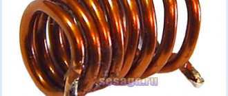
- Tact buttons - close or open a contact. For conventional tact buttons, the legs are connected lengthwise through the body (see picture below). Switches - usually have three contacts, common COM , normally open NO and normally closed NC . When the button is released, the COM-NC ; when pressed, the COM-NO .
Connection and tightening
From the lesson about digital pins, you remember that the microcontroller can read the voltage from its leg. Accordingly, the button can apply to the pin the level to which its second leg is connected. In the same lesson, we discussed that a digital pin that is not connected anywhere receives interference from the air, and the value read from it will be almost random. That is, by connecting a 5V (high-level signal) to the pin via a button, we will not achieve anything: when the button is pressed, a clear high-level signal will be read on the pin, and when released, a random value will be read. To solve this problem, there is such a thing as pin pull. The pull-up is performed to ground (pull down) or power supply (pull up) of the microcontroller using a resistor. The pull-up is performed opposite to the received signal, i.e. if you need to catch a high signal, the pull-up is performed to the ground; if you need to catch a ground signal, the pull-up is performed to the power supply. Here are two options for connecting the button, with pull-up to VCC and GND, respectively:
How is the resistor value selected? Everything is very simple here: when you press the button, current will flow through the resistor, since in any case the power-ground circuit is closed. The higher the current, the greater the energy loss and heating of the resistor, and no one needs this, so the resistance of the pull-up resistor is usually selected in the range of 5-50 kOhm. If you set it more, the pull-up may not provide a stable signal level on the pin, and if you set it less, there will be more energy loss in heating the resistor: with a resistance of 1 kohm, a current of 5 V/1000 Ohm = 5 mA will flow through it, for comparison, the Arduino board with MK in active mode it consumes 20-22 mA. Most often, a 10 kOhm resistor is used for pull-up. As you remember from the lesson about digital pins, the AVR MK has built-in resistors for all GPIOs, these resistors are connected to the power (to VCC ), that is, they literally duplicate the first circuit from this lesson and allow you not to use an external resistor. Microcontrollers of other architectures may have a pull-up to GND, or may not have an internal pull-up at all. When using a power pull-up, we will receive an inverted signal - the digitalRead() function will return 1 when the button is released, and 0 when pressed (when using a normally open button). Let's connect the button to pin D3 (and GND):
void setup() { Serial.begin(9600); pinMode(3, INPUT_PULLUP); } void loop() { // will print 0 if the button is pressed // and 1 if not Serial.println(digitalRead(3)); delay(10); }
Post types
There are many different push-button remote controls on the electrical equipment market that can be used to control equipment and machines. It is worth noting that the differences between many of them can be traced mainly in the design of the case and the brand, while the functionality and design of many are completely identical.
Therefore, from the manufactured devices, only the main ones with justified technical differences are distinguished:
- PKE, with the help of which the control of metal and woodworking units for industrial and household purposes is carried out;
- PCUs intended only for industrial equipment where there is no threat of explosion;
- PKT used for units with a lifting and loading mechanism.
Algorithms
Practicing pressing
In most real-life applications, working with the current state of a button is very inconvenient, for example when the action must be performed once when the button is pressed, i.e. on click. Let's complicate the design a little by adding one flag that will remember the state of the button. This design allows you to track the pressing and releasing of a button and respond to them once:
void setup() { Serial.begin(9600); pinMode(3, INPUT_PULLUP); } bool flag = false; void loop() { // read the inverted value for convenience bool btnState = !digitalRead(3); if (btnState && !flag) { // click handler flag = true; Serial.println("press"); } if (!btnState && flag) { // release handler flag = false; //Serial.println("release"); } }
Contact bounce
The button is not ideal, and the contact does not close immediately; it “rattles” for some time. Running this algorithm, the system polls the button and conditions in approximately 6 μs, that is, the button is polled 166,666 times per second! This is enough to get several thousand false positives.
You can get rid of contact bounce both in hardware and in software: in hardware, the problem is solved using an RC circuit, that is, a resistor (~1-10k) and a capacitor (~100nF). It looks like this:
Programmatically, you can enter a simple click timer based on millis(); let’s take the debouncing time to be 100 milliseconds. This is what the code will look like:
void setup() { Serial.begin(9600); pinMode(3, INPUT_PULLUP); } bool flag = false; uint32_t btnTimer = 0; void loop() { // read the inverted value for convenience bool btnState = !digitalRead(3); if (btnState && !flag && millis() - btnTimer > 100) { flag = true; btnTimer = millis(); Serial.println("press"); } if (!btnState && flag && millis() - btnTimer > 100) { flag = false; btnTimer = millis(); //Serial.println("release"); } }
It is, of course, recommended to use the hardware method, since it does not load the kernel with unnecessary calculations. In 99.99% of projects, software anti-debounce will be sufficient, so feel free to use the construction with millis().
“Pulse” hold
In devices with button control, it is very often necessary to be able to change the value either by clicking the button once, or “automatically” with the same step - by holding it down. This option is implemented very simply by adding one more condition to our previous algorithm, namely: if the button was pressed but not yet released, and more time has passed than the specified one, the condition will return true. In the example below, the frequency of “clicks” while holding is set to 500 milliseconds (2 times per second):
void setup() { Serial.begin(9600); pinMode(3, INPUT_PULLUP); } bool flag = false; uint32_t btnTimer = 0; void loop() { // read the inverted value for convenience bool btnState = !digitalRead(3); if (btnState && !flag && millis() - btnTimer > 100) { flag = true; btnTimer = millis(); Serial.println("press"); } if (btnState && flag && millis() - btnTimer > 500) { btnTimer = millis(); Serial.println("press hold"); } if (!btnState && flag && millis() - btnTimer > 500) { flag = false; btnTimer = millis(); //Serial.println("release"); } }
It will be inconvenient to use such code directly, so you can “wrap” it in a class (read the lesson about classes and the lesson about writing libraries).
The simplest button class
This is how the previous example can be made into a class (we did it in this lesson), put it in a separate file (button.h) and use it:
button.h
class button { public: button (byte pin) { _pin = pin; pinMode(_pin, INPUT_PULLUP); } bool click() { bool btnState = digitalRead(_pin); if (!btnState && !_flag && millis() - _tmr >= 100) { _flag = true; _tmr = millis(); return true; } if (!btnState && _flag && millis() - _tmr >= 500) { _tmr = millis(); return true; } if (btnState && _flag) { _flag = false; _tmr = millis(); } return false; } private: byte_pin; uint32_t_tmr; bool_flag; };
And an example with this “library”: // the file is in the same folder with the sketch #include “button.h” button btn1(3); // specify the pin button btn2(4); void setup() { Serial.begin(9600); } void loop() { // the click() method “fires” once when you click // and pulses when you hold it if (btn1.click()) Serial.println(“press 1”); if (btn2.click()) Serial.println("press 2"); }
Other button options
The button only in appearance seems to be a simple device that gives 0 and 1, but with imagination and time, you can come up with many more uses for a regular button. My GyverButton library implements a lot of interesting features for working with a button, here is the list:
- Working with normally closed and normally open buttons
- Working with PULL_UP and PULL_DOWN Polling a button with software contact anti-bouncing (adjustable time)
- Practicing pressing, holding, releasing, clicking a button (+ setting timeouts)
- Practicing single, double and triple clicks (taken separately)
- Processing any number of button presses (the function returns the number of presses)
- Function for changing the value of a variable with a given step and a given time interval
- Ability to work with “virtual” buttons (all library features are used for matrix and resistive keyboards)
A detailed description of the library can be read in the header file on the library page; there are also many examples there.
Arduino button rattling
While working with buttons, we may encounter a very unpleasant phenomenon called button bounce. As the name itself suggests, this phenomenon is caused by chattering of the contacts inside the push-button switch. The metal plates do not come into contact with each other instantly (albeit very quickly for our eyes), so voltage surges and dips occur for a short time in the contact area. If we do not foresee the appearance of such “garbage” signals, then we will react to them every time and can lead our project to house.
To eliminate bounce, software and hardware solutions are used. In a nutshell, we will just mention the main methods of chatter suppression:
- We add a pause of 10-50 milliseconds in the sketch between the collection of values from the Arduino pin.
- If we use interrupts, then the software method cannot be used and we form hardware protection. The simplest of them is an RC filter with a capacitor and resistance.
- For more accurate debouncing, a hardware filter using a Schmidt trigger is used. This option will allow you to get a signal of almost ideal shape at the input to the Arduino.
You can find more detailed information on ways to deal with pinging in this article on eliminating pinging buttons.
Important Pages
- GyverKIT kit - a large Arduino starter kit of my design, sold in Russia
- Catalog of links to cheap Arduins, sensors, modules and other hardware from AliExpress from trusted sellers
- A selection of libraries for Arduino, the most interesting and useful, official and not so
- Complete documentation on the Arduino language, all built-in functions and macros, all available data types
- A collection of useful algorithms for writing sketches: code structure, timers, filters, data parsing
- Video lessons on Arduino programming from the “Arduino Engineer's Notes ” channel are some of the most detailed in RuNet
- Support the author for his work on the lessons
- Feedback - report an error in the lesson or suggest an addition to the text ( [email protected] )
5 / 5 ( 12 votes)
Types
Main types:
PKE
Typically used when working with woodworking devices for both industrial and domestic purposes.
PKU
Used in industry
, where there is no threat of explosion, and the total concentration of dust or gas will not lead to failure of such equipment.
PCT
Used when working with electrical equipment
, installed on mechanisms capable of lifting large loads, for example, beam cranes, overhead cranes, and so on. With the help of such a device, the tool will be controlled from the surface of the earth in manual mode.
Rules for operating control devices
Many models are not designed to work in explosive environments, so you should familiarize yourself with the technical specifications before purchasing. The operating temperature in the room or workshop should be within -35 – +40°C.
The posts operate in various areas, which are located no higher than 4300 m above sea level.
To ensure long-term operation of devices, it is necessary to monitor the humidity of the environment
(50% is considered acceptable). An increased level of moisture affects the condition of the contacts and disables them. In addition, it is important to monitor the degree of dust and gas contamination in the room. Large amounts of dust and gases can cause fire or smoke.
During operation of the post, do not allow the body to be exposed to sunlight, this will lead to overheating of the device.
Cost indicators
The cost of Russian push-button posts is quite low and depends primarily on the number of buttons
, categories of placement and climatic modification. Devices in a metal case are slightly more expensive than analogues installed in a plastic case.
For example, the price of two-button devices “PKE-222-2” is in the range of 250.0...280.0 rubles. A similar device with a mushroom-shaped “Stop” button will cost a little more – 380.0 rubles.
The price of one-button posts does not exceed 150 rubles. The six-button telpher remote control “PKT-60” costs 300.0 rubles. A device with a similar number of buttons and electrical parameters, equipped with a key (“foolproof”), will cost 200.0 rubles more.
Lighting fittings
The most popular in our time is LED fixtures based on semiconductors - these technologies can no longer be called innovative, but they are the most progressive of the developed ones. LED lamps, indicators, signal lights, etc. provide truly bright lighting, have a very long service life, are reliable and require almost no repairs. In addition, as is known, these are very economical devices to operate.
The shape, size and design of lighting devices are varied. Complex products can contain not only lamps, but also displays that demonstrate certain indicators that exist on the device at the current moment in time. Some sirens operate simultaneously in both sound and flickering, pulsating light signal modes, which allows you to attract attention from a greater distance and much faster.