NTC sensors with resistors, with a resistance that is particularly sensitive to temperature, are common due to their simplicity, low cost, and efficiency. Negative Temperature Coefficient means that as temperature increases, the sensor resistance decreases. The product is installed wherever it is necessary to monitor the temperature, in devices that depend on it: refrigerators, washing machines, boilers, heated floors. Thermal sensors are used for homemade products, for example on Arduino. The equipment picks up the signal from the STC sensor and operates according to the settings. Let's consider the operating principle, types, characteristics and capabilities of NTC detectors and thermistors, where they are used, how to calculate, select.
Concept of NTC temperature sensors
In normal use, resistors do not need their resistance (R) to change with temperature. The dependence is minimal, otherwise the element would influence the circuit, for example, the diode would change the intensity of the glow in an uncontrolled manner. But if it is required that its brightness be a function of temperature, then a thermistor is used - a resistor, resistor. which is sensitive even to small shifts in t°. This property is reflected by the main characteristic - the curve of the R/T graph.
Negative Temperature Coefficient - “negative (minus) coefficient t°”, also known as NTC. This is the most common type of temperature sensors, as they are cheaper than all others, with good efficiency, sufficient for most devices.
Advantages, comparison with other temperature sensors
Advantages:
- significant steepness of the R/T curve, small deviations from nominal values, which indicates good sensitivity;
- minimum response time;
- significant TCS values, that is, greater sensitivity, increased degree of change in R depending on t° (about 2–10% per Kelvin);
- resistance shows a large, precise, predictable decrease as operating temperatures at the resistor core increase;
- extreme compactness, thermistors are suitable for any board, even for spaces measured in mm (there are standard sizes in the form of beads), so sensors with them are compact;
- better strength, reliability, stability, suitability for extreme environments, noise immunity in its operating ranges;
- economical, less labor-intensive to maintain. If the curve is correct, then calibration will not be required during installation and throughout the entire service life;
- It is easy to find out the required resistance at a specific temperature from the curve.
Advantages and disadvantages:
| Compared to RTD | Compared to thermocouples | ||
| Flaws | Advantages | Advantages | Flaws |
| less accurate (but not much) t° range less than RTD | response is faster | accuracy is similar with other advantages | Smaller range, thermocouples operate at higher temperatures (+600° C) |
| greater sensitivity, stability, correctness within one’s working framework; | |||
| simple operation, which reduces the price, no amplifiers, interpreters, etc. are required | |||
| smaller, convenient size | |||
| low cost (one of the main advantages) | |||
| resistance to shocks and vibrations is higher | |||
Parameter coefficients and current-limiting properties are several times better than those of Si temperature sensors. An order of magnitude higher (from 10 times) than that of RTDs (metal thermal detectors).
Compared to RTDs (platinum), the R/T line is steeper, which reflects better sensitivity. But still, the first ones are the most accurate (±0.5% of the measured t°) and they are the best for the limits of −200...+800° C, which is wider than NTC, but the advantage of the latter is that it is cheap and simple.
ntc thermistor - characteristics (volt-voltage characteristics), connection, performance check
NTC thermistors are a special type of resistor that has a negative temperature coefficient. This is its main feature, which is clear from the word “thermo”. Its internal resistance decreases as the temperature rises. Typically, these radio components are used in temperature sensors due to their current-limiting properties.
The value of this coefficient for a thermistor is several times higher than for silistors - temperature sensors made on a silicon basis and more than an order of magnitude higher (that is, 10 times) than for RTD sensors.
The operating range of the thermistor lies in the range from -50 to +200 degrees. This article describes all the features and differences, the device and connection diagram of this radio component, as well as how and where they can be used.
The article also contains a video and one scientific article devoted to the issue under consideration.
Characteristics of NTC thermistors
Unlike RTDs (resistance temperature detectors) that are made of metals, NTC thermistors are usually made of ceramics or polymers. Different materials used result in different temperature responses as well as other characteristics.
Although most NTC thermistors are generally suitable for use in the temperature range of -55°C to 200°C, where they give the most accurate readings, there are special families of NTC thermistors that can be used at temperatures approaching absolute zero (-273.15° C), as well as those specifically designed for use above 150°C. The temperature sensitivity of an NTC sensor is expressed as "percentage change per degree C". Depending on the materials used and the manufacturing process, typical temperature sensitivity values range from -3% to -6% per °C.
An NTC thermistor is a temperature-sensitive resistor whose resistance exhibits a large, precise, and predictable decrease as the temperature of the resistor core increases over a range of operating temperatures.
Three different NTC thermistors
NTC characteristic curve
As can be seen from the figure, NTC thermistors have a much steeper resistance-temperature slope compared to platinum alloy RTDs, resulting in better temperature sensitivity.
However, RTDs remain the most accurate sensors, accurate to within ±0.5% of the measured temperature, and are useful over a temperature range of -200°C to 800°C, much wider than NTC temperature sensors.
Table of main characteristics of NTC thermistors.
Comparison with other temperature sensors
Compared to RTDs, NTCs are smaller in size, faster in response, more resistant to shock and vibration, and have a lower cost. They are slightly less accurate than RTDs.
Compared to thermocouples, the accuracy obtained from both is similar; however, thermocouples can withstand very high temperatures (on the order of 600 °C) and are used in place of NTC thermistors, where they are sometimes called pyrometers.
However, NTC thermistors provide greater sensitivity, stability, and accuracy than thermocouples at lower temperatures, and are used with less power and therefore have lower overall costs.
The cost is further reduced by eliminating the need for signal conditioning circuits (amplifiers, level translators, etc.) that are often needed when working with RTDs and are always needed for thermocouples.
- Temperature Range: The approximate general temperature range in which the sensor type can be used. Within a given temperature range, some sensors perform better than others.
- Relative Cost: Relative cost as these sensors are compared to each other. For example, thermistors are inexpensive relative to resistance thermometers, in part because the material of choice for RTDs is platinum.
- Time constant: The approximate time required to change from one temperature to another. This is the time in seconds that the thermistor takes to reach 63.2% of the temperature difference from the initial reading to the final reading.
- Stability: The ability of the controller to maintain a constant temperature based on feedback from the temperature sensor.
- Sensitivity: degree of response to temperature changes.
Principle of operation
The sensor alloy changes conductivity at different temperatures. Resistance decreases as it increases, and increases as it decreases. Electrical parameters change, which is recorded by the circuit.
The microcontroller of the serviced device, based on the received data, taking into account the specifications of the detector, calculates the t° shifts. Then it sends a signal to the executive unit (relay, heater, cooling system) to act at a particular t° level.
Example: taking into account the described algorithm, the voltage is controlled at the input of the thermostat comparator, adjusted according to the temperature characteristic, and it undergoes changes.
The NTC sensor itself is not an electronic device, it only records. It is based on a nonlinear dependence of resistivity. resistor depending on the temperature of the environment. The operating scheme may be simpler: a simple output on a value display or a relay can react immediately.
Sensors are sensitive to electromagnetic radiation and fields, so they are shielded or mounted at a distance from the sources of such phenomena (power wires).
What is a thermistor?
A regular resistor has a relatively stable resistance. Of course, the electrical resistance of a conventional resistor can change when it is significantly heated (within tolerances). But in normal mode, the readings of these devices are stable, which is what the developers are striving for.
In the manufacture of thermistors, materials are deliberately selected whose resistance depends on temperature. That is, a thermistor is a semiconductor device whose resistance depends on temperature. It can be said that by heating or cooling such semiconductor devices, their resistances can be controlled.
Rice. 1. Thermistor and its image on the diagrams
The temperature dependences of semiconductor resistors are widely used in practice, which will be discussed below. Let us only note that thermistors are, in fact, variable resistors, the resistance of which does not change mechanically, but depends on the degree of heating and the temperature characteristics of the semiconductor materials used. Moreover, it does not matter whether the temperature indicators changed due to direct or indirect heating.
How are they different from thermocouples?
NTC should not be confused with thermocouples: although the tasks are similar and there is a connection with electrical parameters, the principle is different. For the former, it is based on a change in the resistance of the sensitive part, for the latter, on the potential difference that changes during temperature transformations, created by two segments from different alloys with different electrical properties.
The NTC sensor is made of one solid piece of alloy, and the thermocouple is made of two metals, and measurements are based precisely on transformations of its resistance, and not on potential differences.
Application
Thermistors are mainly used to protect equipment and various devices from overheating and possible overloads. Less often, the dependence of the resistance stabilizes the operation of the heating element.
Examples of using:
Most circuits use the ability of thermistors to convert internal energy into an electrical signal that is read by automation.
In heating devices, a thermistor is quite often used as a self-resetting fuse. Its resistance increases when a critical temperature is reached and, as a result, the electrical circuit opens.
After cooling, the device restores functionality. The areas of application can be listed for a very long time, but these examples also show how popular thermistors and thermistors have turned out to be.
Design of temperature sensors and NTC thermistors
Other names are resistive sensors, thermistors, thermal or thermistors, NTC temperature sensors or resistance thermometers (but specifically with an NTC thermistor, not to be confused with RTDs and products with other sensitive parts).
The NTC sensor consists of a resistive (sensitive) segment - a thermistor and wires (legs) for supplying current to it.
The thermistor is made by powder method, baking.
Materials: oxides, halides, chalcogenides. Semiconductors (often polymer) are used; they themselves have a TCS “−”. For the body and outer coating - ceramics, glass, epoxy.
Where to order temperature sensors
If you want to purchase temperature sensors on favorable terms, contact our company. Consultants will help you select components with suitable characteristics and provide detailed information about the selected products.
By ordering NTC thermistors on our website, you are guaranteed to receive the following benefits:
- Availability of goods. Components for refrigeration equipment and climate control equipment will not have to be purchased to order, wasting extra time.
- Moderate prices. We adhere to a loyal pricing policy and offer customers high-quality products at competitive prices.
- Prompt delivery. You will receive the ordered goods on time. Our employees will arrange for the temperature sensors to be sent on the day your application is accepted.
Contact our specialists to consult on any questions you may have and make a purchase.
Our company provides a wide range of products and services for
,
, and .Call!
Standard sizes
Standard sizes of thermistors themselves: rods, tubes, disks, beads, plates, drops, tablets. Sizes 1–10 µm to several mm and 1 cm.
There are also SMD formats and micro-rectangles.
We can immediately distinguish between the sensors as ready-to-use products and the “bare” thermistors themselves.
Sensors as devices can be made in any form, housing according to the manufacturer’s decision, for example, probes, probes, “chips” with connectors, in a waterproof housing, with threads, on a long cable.
Sensors as ready-made devices
Automotive:
Invoices. On the surface of structures. Examples: T2C-NTC 10K for −50…+150° C; ALTF02 S+S for collecting data from solid objects (pipes).
Channel, submersible. For cavities. T3-NTC 10K with 30 cm cable, for +50…−50° C; T2I-NTC 10K, 6.5 cm, −50…+150° C; TF43T and TM54 for liquids in pipes and containers.
External. For weather-sensitive complexes, on external walls (ATF01 S+S Regeltechnic).
Rooms. For interior spaces, apartments, offices.
Multifunctional. They combine other sensors to study not only temperature, but also pressure, density, etc.
Beaded
Beads, ball, drop, Ø 0.075 to 5 mm. Made of lead wires, an alloy with platinum, sintered in a ceramic, glass-ceramic shell. Better response and stability, their operating temperatures are higher than those of disk variants and chips.
Disadvantages: higher fragility, no interchangeability, require individual calibrations. There are no exact standards for their R/T ratings.
Discs, records, chips, tubes
Disc-shaped products with surface contacts. The shape is larger, the reaction is slower than that of balls. But due to their increased dimensions, they have good dissipation (power to increase temperature by 1 degree). Since the energy dissipated is proportional to the square of the current, they work better with high currents than balls.
Disc ones are made by pressing powder-like oxides into a round matrix, then sintered. Chips are injection molded, the suspension is distributed into a thick ball, then dried and cut. Dimensions Ø 0.25…25 mm.
Interchangeable, but there are errors, the minimum permissible deviation is considered to be at least 0.05 ° C within 0...+70 ° C. A standard 10 kOhm thermistor within the range of 0…+100 has coefficients close to the following:
Tube thermistor:
Encapsulated
Encapsulated ones resemble wafers, tablets, and may be similar to other types. The peculiarity of their coating is that it is especially sealed, airtight (bubble, capsule, container), made of fiberglass. For high temperatures, from +150° C, for boards where special strength is required. This design increases stability, protection, Ø 0.4…10 mm.
Technical specifications
A wide variety of thermal resistance models are dictated by the needs of the modern electronics industry. The technical parameters of semiconductor-type products make it possible to fully satisfy the demand of manufacturers of radio-electronic and electrical devices.
The main parameters include:
Semiconductor thermistors have high sensitivity in combination with negative TCR values. They are easy to manufacture, have tiny sizes, and are easily integrated into microcircuits. All these properties make thermistors indispensable in microelectronics.
Semiconductor thermistors are connected via a bridge circuit. This connection allows you to automatically adjust the required parameters of electrical circuits. Sometimes for these purposes it is necessary to use rather complex automation schemes.
The parameters of metal thermistors are more suitable for electrical devices, in particular, they are used as temperature sensors. They can be seen in water heating systems, or in resistance thermometers. These types of sensors (Fig. 7) are very reliable in operation and have a fairly wide measurement range.
Rice. 7. Temperature sensor
Sensors of this type are connected according to a simple scheme. If calibration or temperature adjustment is required, this is usually done manually using a potentiometer. A simple diagram of connecting a temperature sensor is shown in Fig. 8. By changing the voltage with a potentiometer, you can influence the TCR value. You can visually control the temperature using an ammeter, the scale of which is graduated in degrees.
Rice. 8. Simple diagram for connecting a thermistor
NTC and PTC temperature detectors
There are two types of thermistors: the direction of the dependence of R on temperature and the TKS mechanism differ. The word before the abbreviation of the phrase “Temperature Coefficient” reflects this nuance:
- Negative. NTCs we are considering. With negative t° coefficient. As the temperature increases, the resistance decreases;
- Positive, PTC. The second name is posistors. With positive t° coefficient. R increases.
For NTC thermistors, mixtures of multicrystalline transition metal oxides (MnO, CoOx, NiO and CuO), semiconductors of certain types (A, B), and glass-like (Ge and Si) are used. And PTC (posistors) consist of solids based on BaTiO₃; this alloy has a positive reaction (TCR). But the differences in operation are mainly only in the direction of the R/T relationship.
The most popular mid-range NTC temperature detectors: TKS −2.4…-8.4%/K, with wide resistance limits. (1...106 Ohm). If we talk about PTC, then these numbers are 0.5...0.7%/K, they are often made of silicon, their resistance, unlike NTC, is close to linear.
PTCs are used on cooling equipment, temperature stabilization in electronic circuits, and as self-regulating heating parts. Their R increases as their heating increases (PTC heaters), such a spare part will never overheat, and always produces stable heat output over a significant voltage range.
The areas are extremely similar, and the principle is basically the same - it all depends on what is required, negative or positive TCS:
- NTC monitors the temperature drop;
- PTC - for a promotion.
Semiconductor thermal sensors
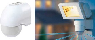
An example of a temperature meter is the NTC, a temperature sensor used to control cooling and prevent freezing. For example, in refrigerated rooms in stores (displays with perishable products).
A device with the opposite functionality is PTC thermistors. Unlike the previous one, this sensor monitors the temperature increase in order to avoid defrosting the contents.
Thermal sensors of this type are manufactured in a waterproof housing, which protects the sensitive element from moisture. The cable length, in most models, is about one and a half meters (if necessary, this parameter is increased by extending the compensation wire)
Types of NTC thermistors
According to the range of values of the serviced NTC environment there are:
- low temperature. For below 170 K (Kelvin, maybe in Celsius);
- average, 170...510 K;
- high, from 510 K;
- ultra-high, 900…1300 K.
A separate type is combined, with indirect heating. They combine a resistor and a heating element “galvanically isolated” from it, which sets the temperature and, accordingly, the resistance. They are used as variable resistors controlled by the voltage supplied to their heating part.
Basic parameters of NTC thermistors and posistors
Currently, the industry produces a huge range of thermistors, posistors and NTC thermistors. Each individual model or series is manufactured for operation in certain conditions, and certain requirements are imposed on them.
Therefore, simply listing the parameters of posistors and NTC thermistors will be of little use. We'll take a slightly different route.
Every time you get your hands on a thermistor with easy-to-read markings, you need to find a reference sheet or datasheet for this thermistor model.
If you don't know what a datasheet is, I advise you to take a look at this page. In a nutshell, the datasheet contains information on all the main parameters of this component. This document lists everything you need to know to apply a specific electronic component.
I had this thermistor in stock. Take a look at the photo. At first I knew nothing about him. There was minimal information. Judging by the marking, this is a PTC thermistor, that is, a posistor. That’s what it says on it – PTC. The following is the marking C975.
At first it may seem that it is unlikely that it will be possible to find at least some information about this posistor. But, don’t hang your nose! Open the browser, type a phrase like these into Google: “posistor c975”, “ptc c975”, “ptc c975 datasheet”, “ptc c975 datasheet”, “posistor c975 datasheet”. Next, all that remains is to find the datasheet for this posistor. As a rule, datasheets are formatted as a PDF file.
From the datasheet I found on PTC C975, I learned the following. It is produced by EPCOS. Full name B59975C0160A070 (B599*5 series). This PTC thermistor is used to limit current during short circuits and overloads. Those. This is a kind of fuse.
I will give a table with the main technical characteristics for the B599*5 series, as well as a brief explanation of what all these numbers and letters mean.
Max.operating voltage (TA = 60°C) – VMAX . Maximum operating voltage at ambient temperature 60°C. As you can see, it is 20 volts direct (VDC) or alternating (VAC) current. This is the maximum voltage that the posistor can withstand.
170°C, and a temperature of 160°C is the reference temperature ( Tref ). I would call this temperature the “transition temperature.”
Tolerance of RR – ΔRR . Permissible deviation from the nominal resistance. Expressed as a percentage. For example, for a C975 posistor, the nominal resistance RR (Rated resistance) is 1.8 Ohms. In reality, it can be from 1.35 to 2.25 Ohms, since the Δ RR is ±25%.
Now let's turn our attention to the electrical characteristics of a particular product, in our case it is a PTC C975 posistor (full marking B59975C0160A070). Take a look at the following table.
Therefore, the voltage is also specified for the maximum switching current. In this case it is equal to 20 volts. Multiplying 3 amperes by 20 volts, we get a power of 60 watts. This is exactly the power our posistor can absorb when limiting the current.
The following graph will help us understand what RR and Rmin
Calculation, selection of NTC thermistors
They determine which thermistor is suitable by using the R/T curves, by creating graphs and tables of RT values, and by formulas. The procedure is complex, there are entire brochures and separate articles, so we will only indicate the basics.
The best, albeit complex, calculation formula is that of “Steinhart (Steinhart) - Hart”:
Calculations are usually done by radio electronics fans and specialists, especially for homemade products. It will be easier to select an element with a similar specification, and also use ready-made recommendations from specialists; the information is available online on special sites. There are hundreds of modifications of thermistors; accordingly, the specification tables are very large. Often a specific batch of similar series of thermistors has its own data.
There are hundreds of NTC thermistor specifications:
But still, calculations in most cases are extremely desirable, even if there is data from the manufacturer on the parameters and recommendations, since thermistors have highly nonlinear properties. Different copies of the same specification, even, for example, with the same values of B25/100 (sensitivity, we will consider below), may have different shifts R. Therefore, the formulas for this parameter provide only an approximate estimate. Accurate results require complex calculations.
Sensors for household or other appliances in factory standard sizes are devices in a housing that are completely ready for use, and so on, all the necessary calculations are made by the manufacturers.
Parameters for selection (usually displayed as graphs, diagrams):
- CVC;
- temperature/resistance ratio curve;
- heat capacity, dissipation constant;
- R values;
- tolerances;
- temperature Range. It is within their boundaries that NTC sensors can perform better than all similar products;
- time constant: the period for transition from one t° value to another. This is the period in seconds required to achieve 63.2% difference in t° from the initial reading to the final reading;
- sensitivity: level of response to temperature changes;
- stability of the controller while maintaining a constant temperature through feedback from the sensor.
First order approximation
The t°/Ohm dependence (RT graph) has significant nonlinearity, therefore, for practical circuits, so-called approximations are used for calculations. An example of such a “first order”:
The equation is valid only for a small temperature range and for t°, when k is almost constant at its different values.
Beta formula
There is also a beta equation (contains a constant "beta", β). This is the simplest formula that exists, often for homemade products, for example, this is what is used on Arduino. Gives results with an accuracy of ±1 °C. Covers the range 0…+100° C. The latter is dependent on a single material constant β, obtained by measurements (indicated in the thermistor specification).
There is no need to linearize the sensor response. The formula requires a 2-point calibration, typically no more than ±5 over the entire useful range.
Steinhart-Hart equation
The Steinhart-Hart algorithm is a better but more complex equation. To avoid complications, the previous method is usually used, but for users with algebra knowledge and calculation experience, this is the best method. This is the general formula to fit a thermistor curve:
The A, B, C constants are usually published by manufacturers and suppliers as part of thermistor specification tables. The deviation according to the described formula is about ±0.15° C within −50…+150° C, which is an excellent indicator. If high correctness is required, then the boundaries must be narrowed. The accuracy is ±0.01° C and is better observed within the range of 0…+100° C.
Which formula to choose
The selection of a suitable calculus for determining temperature from resistance measurements is based on the availability of computing power, and most importantly, on tolerance requirements. For some applications the 1st order approximation is sufficient, for other cases the Steinhart-Hart method is required and the sensor must be calibrated over a large number of measurements against a generated lookup table.
Correction for self-heating of the thermistor
When working in any electrical circuit, a measuring current flows through the thermistor; if its value is more than 100 μA or the resistance of the thermistor is small, then the measurement result is distorted. This phenomenon is called self-heating and, as mentioned earlier, depends not only on the load, but also on the materials used and the design of the sensor. In other words, a correction must be made to the obtained measurement result, which can be calculated using the following formula:
where TA is the actual value of the controlled temperature; T is the measured temperature value; U is the instantaneous value of the voltage across the thermistor, I is the instantaneous value of the current flowing through the thermistor; R(T) is the resistance value of the thermistor corresponding to temperature T; δth is the thermal dissipation coefficient.
In relation to the circuit used and provided that a microcontroller with a 12-bit ADC is used, expression (20) will look like this:
In the applied switching circuit (Fig. 2), the larger the resistor value in the feedback of the operational amplifier ROC, the smaller the correction value. It should be noted that the obtained correction values for temperature (Table 9) are valid only for the indicated thermistors, converter R(T)
U(T), as well as for the dissipation coefficient in air equal to 1.5 mW/K. When using a thermistor in any other environment, it is necessary to determine the value of this coefficient experimentally.
Table 9. Self-heating correction for thermistor B57861S0103F040
Characteristics of NTC thermistors
We will describe the main points and tools for determining suitable thermistors.
Ratio t°/Ohm (RT curve)
Most NTC detectors are suitable for the temperature range of −55...+200° C, where they are most accurate. But there is also a special family for temperatures close to abs. zero (−273.15 °C), as well as for values above +200.
The figure shows the general trend; specific numbers depend on the specification and denomination. The curve clearly shows the feature of the NTC type: t° increases, resistance. decreases. In posistors (PTC) it’s the other way around, and they have a nuance: they have a kind of breaking point, at which the resistance greatly changes. at some values, so working with them is more difficult. This is one of the reasons why most not very expensive and relatively simple devices are equipped with STC detectors.
Temperature sensitivity is expressed as % change per 1 degree Celsius. Typical sensitivity values range from −3 to −6% per 1°.
Heat capacity and self-heating
Self-heating occurs when current flows through a thermistor. Since it is a resistor, energy is dissipated in the form of heat, which affects the accuracy of the measurements. The level of this phenomenon depends on the current strength, the environment, as well as on the TKS, the number of parts on the segment. The fact that heating affects the resistance, current carrying capacity of the detector, and depends on environmental conditions makes the part indispensable for use in tanks containing liquid.
Thermal capacity refers to the amount of heat required to increase the temperature of the sensor by 1° C, expressed in mJ/° C. The parameter is extremely important when using a thermal sensor as a limiter for starting relays, since it determines the speed of response of this element.
Sensitivity
Let us characterize sensitivity with an excerpt from a specialized website:
Current-voltage characteristics, operating modes and their application
The selection is also carried out according to the current-voltage characteristic (CVC), which depends on the temperature attached to the device with the STC sensor and on its design.
NTC sensors with a working mark on the descending segment of the current-voltage characteristic are used as relays (starting, temporary) in equipment where the power of electromagnetic radiation of ultra-high frequencies is measured and controlled. And also for heat control systems, fire alarms, in installations that control the flow of liquids and bulk substances.
NTC sensor in the boiler: what is it and how to install it?
Many Russian residents sooner or later face the need to purchase a heater. Today in household appliance stores you can find a huge number of different types and models from various manufacturers - both domestic and foreign. Gas heaters can be single-circuit or double-circuit, with an open or closed combustion chamber, wall-mounted or floor-mounted.
You can find the right boiler to suit every requirement and preference. But they have one thing in common – the gas on which this equipment operates.
A breakdown can not only seriously disrupt the operation of the heater, but also pose a risk to human life. After all, gas is always dangerous. A temperature sensor will help reduce the likelihood of a malfunction.
The devices of this accessory perform several important and useful functions, which we will discuss in this article.
Most modern models of gas heaters have a simple and accessible setup system. But no matter how easy the control, it requires constant attention to adjustment. It is much more comfortable to automate the entire system and not worry about it.
Fortunately, almost all modern boilers are equipped with this feature. However, the autoregulator is able to work correctly only by receiving complete and reliable information about the surrounding conditions. This function is performed by special sensors.
Where exactly are NTC temperature sensors used?
Let us specify where exactly NTC sensors are used.
The most characteristic areas:
- all possible temperature sensors;
- refrigeration, heating, and heating systems where a decrease in temperature is not allowed;
- ventilation and air conditioning systems;
- control over the degree of cooling in pipes, in open locations;
- heated floors, boilers (water heaters), boilers;
- detection of the absence or presence of liquid;
- current limiters;
- temperature monitoring in cars and other units.
To summarize, these are the following temperature directions:
- measurement;
- control, management related to t°;
- compensation processes.
Examples of practical application:
- various thermostats, thermostats for the environment in refrigerators, boilers, for cable ties, surfaces of heating structures;
- thermometers of various media (liquids, gases), including air in rooms;
- heaters for 3D printing devices (to control working areas so that the material does not stick to them);
- car engines, motors of various types, including electric (preventing overheating);
- ovens (preventing burning, burning of cooked food).
When installing film heated floors, NTC remote sensors are placed in a corrugated pipe, for example, standard Ø 16 mm, directly under one of the IR heating strips in the segment of lowest heat transfer (under rugs, furniture with short legs).
NTC detectors can be divided into 3 groups depending on which electrical characteristics are important for certain purposes.
For what purposes are certain characteristics significant?
| Characteristic | Where is it used? |
| Resistance-temperature | For applications, devices for which the temperature/resistance ratio is significant. These are devices for measuring t°, monitoring, control and compensation, and some other related physical processes. The current on the thermistor is kept as low as possible in order to minimize self-heating of such a probe. |
| Current temporary | Devices with a time delay, limiting inrush currents, preventing overloads, overvoltages and other things. Characteristic related to heat capacity, dissipation of ntc sensor. The circuit relies on a thermistor, heats up due to the current across it, at a certain point changes appear. |
| By voltage | For devices based on the characteristics of voltage, current of thermal resistors. These are devices for monitoring environmental conditions, parameters on the circuit, which initiate changes in the operating level on a given circuit curve. Also for current limitation, temperature compensation, t° measurements. |
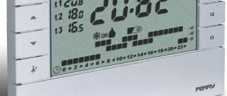
Types of thermostats
These devices serve to maintain a constant ambient temperature (water or air). Thermostats are used everywhere in household appliances, including dishwashers. They are necessary to control the water heating temperature at different washing modes. There are 3 types of temperature sensors: gas-filled, bimetallic and thermistors (thermistors). Gas-filled thermostats include a sensitive sensor, a cylinder with a tube filled with freon, and a control device. When the water temperature rises, the refrigerant expands and presses on the plate, which opens the contacts and turns off the tubular electric heater.
The operating principle of bimetallic sensors is based on closing (opening) a contact during the heating and cooling of a plate made of 2 metals with different temperature coefficients of expansion. However, most modern dishwashers use thermistors. As the temperature of the substance being measured increases, the material of these sensors changes the resistivity, sending a signal to the control module. The electronic board, in turn, turns off the heating element. Structurally, thermistors are much more reliable than their analogues, since they do not have a mechanical circuit.
Designation on the diagram
On the diagrams, NTC is indicated by a rectangle (empty) crossed out by an oblique line at the bottom with a horizontal leg; there is also a “t°” icon with a minus. PTC posistors have “+”.
Another designation option is a schematic image of a spiral (like the teeth of a cardiogram), crossed out by an oblique line with the same temperature symbol:
Schemes, connection
Schemes are used for homemade products and assemblies. This question, like calculations during selection, is a separate large topic, so we will describe only the basics to orient the reader.
Circuit diagram for ATmega and Arduino (programming will also be required):
The assembly below uses a TH10K thermistor and a 10k ohm resistor as R (balance):
Another diagram:
NTC sensor: what is it, types, methods of application, connection diagrams
Temperature sensors are used wherever the operating parameters of the system in one way or another depend on temperature factors. Today, various types of temperature sensors are produced: thermocouples, thermistors, thermistor sensors with a linear dependence of the output signal, as well as semiconductor sensors with a digital output.
Temperature Devices (RTDs) operate by passing electric current through them and are used in bridge circuits.
Checking and replacing NTC temperature sensors
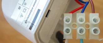
The installation itself is elementary - the sensor is plugged into the mounting socket, the cores of its cable are connected to the terminals, and the wires can also be connected by twisting, soldering, or crimping. Typically, the power wiring goes to the thermostat or thermostat board.
Below in the photo is a replacement sensor for measuring the temperature in a room with a 5-meter cable for a heating boiler. Control and adjustment are carried out by a thermostat; it can be included with the unit or purchased separately.
Breakdowns, diagnostics, repairs
NTC sensors usually break down due to environmental influences, for example, in boilers, scale gets stuck on them, and coolant gets inside.
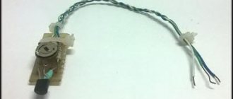
The test consists of measuring the resistance with a multimeter at a certain temperature and comparing the result with the specification. In our case, the 2 tested sensors in the photo below are working, R is about 10 kOhm, which corresponds to approximately +25° C (the temperature of the room where the products are located).
The sensor was placed on a metal weight for cooling, we see that the resistance. as the temperature decreases, it increases (the indicator in the photo corresponds to about +21). In the second photo, the sensor was removed from cooling - R drops with increasing t°.
So, to check you will need a thermometer, a multimeter and a temperature dependence table, which can be downloaded online for specific sensor models for the existing brand of boiler, refrigerator, etc., example (right column - Ohms, left - °C):
Types of failure symptoms:
- if there is no resistance on the sensor, this means a break;
- if R differs greatly from the specification - internal failure of the thermistor itself;
- resistance corresponds to temperature, but in some interval the detector begins to lie or stops measuring altogether. Then the boiler also goes into emergency mode.
Signs of a broken element on the boiler (similar to all household appliances):
- immediately (several seconds) after turning on and activating the pump, it goes into emergency mode;
- after resetting the error, everything repeats;
- after opening the hot water tap, the boiler gives an error. Most likely, the sensor on the warm liquid pipe is broken;
- sudden stop;
- discrepancy between the output temperature and the configured values, the device can constantly heat up (until the limitation, protection against overheating is triggered);
- jumps in temperature or no heating/cooling at all.
The NTC sensor, and especially its thermistor, cannot be repaired - it must be replaced with a similar one. The exception is when the contacts have become sour, scale has appeared, and this is the cause of the breakdown, then the legs of the elements are cleaned.
For appliances and equipment (refrigerators, washing machines, boilers, cars), such products are sold in specialty stores and service centers.
It is advisable to have a known good part in stock in order to carry out diagnostics with 100% accuracy. You just need to connect a new thermistor and see how the unit works.
Almost always, when the boiler, boiler, or floor turns on, that is, the electrical system itself is working, but oddities and incorrect operation related to temperature are observed, the reason being the temperature sensor. It is checked first, especially since the procedure is simple. There are also devices with self-diagnosis - they display an error code on the display, LEDs, and sound, then it is even easier to determine whether the sensor is faulty.
Symptoms of a thermistor failure
Thermistors are usually located in the dishwasher tray. Many users wonder: what signs indicate a problem with the temperature sensor? The most common symptoms are a complete lack of heating or, conversely, excessive heating of the water. Regardless of the selected temperature mode, the water can even heat up to a boil.
The temperature of the machine body also increases; when the door is opened, hot steam comes out of it. In this case, the NTC sensor does not work for some reason, so the electronic board does not turn off the heating element in time.
Modern household appliances support the function of automatic diagnosis of breakdowns. For example, in Miele dishwashers, a malfunction of the temperature sensor is indicated by errors F01 and F02 on the display.