001 Electrical circuits of elevators - reference manual (Yatskevich V.V.) online
002 GENERAL CONCEPTS ABOUT ELEVATOR ELECTRICAL DIAGRAMS AND DEVICES
003 THE SIMPLE DIAGRAMS FOR CONNECTING ELECTRICAL DEVICES IN ELEVATORS
004 EQUIPMENT FOR ACTIVATING A THREE-PHASE INDUCTION ELEVATOR MOTOR
005 DIAGRAM FOR REMOTE CONTROL OF AN INDUCTION ELEVATOR MOTOR
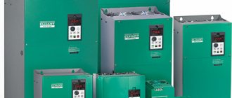
006 ELEVATOR POWER EQUIPMENT
007 ELEVATOR CONTROL EQUIPMENT
008 LIMIT SWITCHES AND INTERLOCKING CONTACTS FOR SAFETY DEVICES
009 PASSENGER ELEVATOR WITH SINGLE SPEED INDUCTION MOTOR
010 DIAGRAM FOR CONNECTING FLOOR RELAYS OF PASSENGER ELEVATOR WITH SINGLE SPEED
011 PASSENGER ELEVATOR FLOOR SWITCH WITH SINGLE SPEED ASYNCHRONOUS
012 DIAGRAM FOR CONNECTING CONTACTORS “UP” AND “DOWN” OF A PASSENGER ELEVATOR WITH
013 ELECTROMAGNETIC TRANSFER OF PASSENGER ELEVATOR WITH SINGLE-SPEED ASYNCHRONOUS
014 OPERATION OF THE CONTROL CIRCUIT OF A PASSENGER ELEVATOR WITH SINGLE-SPEED ASYNCHRONOUS
015 SIGNALING CIRCUIT FOR PASSENGER ELEVATOR WITH SINGLE SPEED ASYNCHRONOUS
016 PASSENGER ELEVATOR WITH LOAD CAPACITY 320 KG AND SPEED 0.71 m/s
017 POWER SCHEME FOR PASSENGER ELEVATOR WITH LOAD CAPACITY 320 KG AND SPEED
018 PRECISION SENSOR FOR PASSENGER ELEVATOR WITH LOAD CAPACITY 320 KG AND
019 CONNECTION DIAGRAM FOR PASSENGER ELEVATOR CONTACTORS WITH LOAD CAPACITY 320 KG
020 OPERATION OF CONTACTORS OF PASSENGER ELEVATOR WITH LOAD CAPACITY 320 KG
021 CONTROL DIAGRAM FOR THE AUTOMATIC DOOR OF THE CAB AND PASSENGER ELEVATOR SHAFT
022 OPENING AND CLOSING DOORS OF A PASSENGER ELEVATOR WITH LOAD CAPACITY 320
023 CONTROL SCHEME OF A PASSENGER ELEVATOR WITH LOAD CAPACITY 320 KG
024 OPERATION OF CONTROL CIRCUIT BY ORDER (PASSENGER ELEVATOR WITH LOAD CAPACITY
025 OPERATION OF CALL CONTROL CIRCUIT. PURPOSE OF RELAY RP1 PASSENGER
026 MODES “CONTROL FROM THE ENGINE ROOM” AND “REVISION” OF THE PASSENGER
027 SIGNALING SCHEME FOR PASSENGER ELEVATOR WITH LOAD CAPACITY 320 KG AND
028 FREIGHT ELEVATOR WITH TWO-SPEED MOTOR AND INTERNAL PUSH-BUTTON
029 OPERATION OF THE COPYING MACHINE OF A FREIGHT ELEVATOR WITH A TWO-SPEED MOTOR AND
030 CONTROL DIAGRAM FOR FREIGHT ELEVATOR WITH TWO-SPEED MOTOR AND INTERNAL
031 OPERATION OF THE CONTROL CIRCUIT OF A FREIGHT ELEVATOR WITH A TWO-SPEED MOTOR AND
032 PASSENGER ELEVATOR WITH COLLECTIVE CALL AND EXECUTION CONTROL
033 DIAGRAM FOR CONNECTING THE RELAY RUB AND RUNES OF THE PASSENGER ELEVATOR WITH COLLECTIVE
034 DIAGRAMS FOR CONNECTING THE CONTROL RELAY OF A PASSENGER ELEVATOR WITH COLLECTIVE
035 PASSENGER ELEVATOR CAB DOOR CONTROL WITH COLLECTIVE CONTROL
036 CONTROL OF PASSENGER ELEVATOR CONTACTORS WITH COLLECTIVE CONTROL
037 CONTROL CIRCUIT OF PASSENGER ELEVATOR WITH COLLECTIVE SOFTWARE CONTROL
038 OPERATION OF PASSENGER ELEVATOR CONTROL CIRCUIT WITH COLLECTIVE CONTROL
039 CONTROL SCHEME OF A PASSENGER ELEVATOR WITH LOADING CAPACITY OF 500 AND 1000 KG FOR
040 PAIR CONTROL OF ELEVATORS
041 PROGRAM FOR PAIR OPERATION OF ELEVATORS
042 DIAGRAM FOR CONNECTING RELAYS AND CONTACTORS FOR PAIR OPERATION OF ELEVATORS
043 KNOTS FOR SELECTING THE DIRECTION OF MOVEMENT AND SPEEDING DURING PAIR OPERATION OF ELEVATORS
044 CLASSIFICATION OF PREMISES ACCORDING TO ELECTRICAL SAFETY
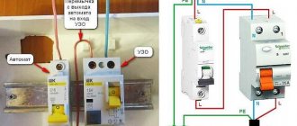
045 GROUNDING EQUIPMENT IN ELEVATORS
046 PROTECTIVE EQUIPMENT WHEN WORKING ON ELEVATOR ELECTRICAL INSTALLATIONS
047 CATEGORIES OF WORK ON ELEVATOR ELECTRICAL INSTALLATIONS
048 TECHNICAL MEASURES TO ENSURE THE SAFETY OF REMOVAL OPERATIONS
049 TECHNICAL MEASURES ON ELEVATORS TO ENSURE WORK SAFETY WITHOUT
050 ORGANIZATIONAL MEASURES TO ENSURE SAFETY OF WORK ON ELEVATORS
051 WORKING WITH ELECTRIFIED TOOLS. ELECTRIC WELDING WORKS ON
052 MEASUREMENT OF INSULATION RESISTANCE IN ELEVATORS
053 REQUIREMENTS FOR ELEVATOR SERVICE PERSONNEL
054 LITERATURE (ELIVATOR ELECTRICAL DIAGRAMS)
Story
The first elevators were driven by a steam engine and controlled by an operator. In 1924, Otis introduced the first automatic elevator controlled by logic relays. This made it possible to increase the speed of movement of the cabin. Thirteen years later, Otis showed a system to help schedule elevator operation during periods of high load. This is what the first automatic elevators looked like:
In 1948, Otis began producing automatic elevators that could already change speed, adapt their schedule to periods of load, and not stop when the cabin was fully loaded. They now have a function for automatically closing the door after a certain period of inactivity.
Relay control was used until the 1980s, when they began to be replaced by microprocessors. Microprocessors used less power and took up much less space.
This is what the Otis elevator relay control system looked like. Picture from the site
Ensuring elevator safety
The design of the operating lifting equipment must ensure its operation in unconditional compliance with safety standards. Therefore, during design, manufacture and installation, all risks that may arise during operation must be taken into account.
Considerable attention is paid to fire safety. This is due to the fact that passengers are in a confined space of small volume, which they cannot quickly leave. Therefore, the cabin itself and its enclosing elements must be made of materials that do not support combustion and do not emit toxins when heated. Elevators must be equipped with fire-resistant doors.
Modern elevator models are equipped with special devices that, when the power supply in the building is turned off, automatically moves the cabin to the floor closest to the emergency stop and opens the doors. This allows passengers to be quickly evacuated.
In addition, the design must provide protection against the following types of threats:
- clamping a person when closing automatic elevator doors;
- interfloor blocking of the elevator cabin;
- cabin fall;
- people falling into the mine through accidentally opened doors.
An emergency fall of the elevator car is prevented by special devices - catchers. They provide a smooth stop when the cabin speed exceeds the limit value. Shock absorbers are used to protect against impact. In the event of an interfloor stop, special equipment securely fixes the cabin and opens the doors. This allows passengers to exit the elevator safely. In addition, the personnel who service the elevator facilities are obliged to take measures to free people in such cases. The cabin dimensions are designed in such a way that it cannot accommodate more people than can be transported according to the load capacity restrictions. In addition, in case of overload, the start of the elevator is blocked.
To prevent people from being pinched by doors, automatic control of their opening and closing is provided using infrared sensors. If there is a person in the opening, they block the doors from closing. In addition, special devices do not allow the doors to open if the elevator car is not supplied to the floor.
Characteristics of elevator facilities
The main technical parameters that characterize the operation of the elevator are:
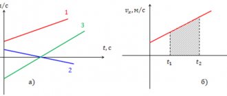
- speed of vertical movement of the cabin;
- load capacity;
- the number of floors, which determines the number of elevator stops;
- maximum lifting height.
Regulatory documents that regulate the requirements for the characteristics of elevator equipment are PUBEL (Rules for the Design and Safe Operation of Elevators) and specialized GOSTs. They also regulate the requirements for servicing elevator facilities.
Key characteristics include elevator speed and lifting capacity. There are several types of speed.
The manufacturer indicates the nominal speed value in the instructions for the lifting equipment. It is provided under optimal operating conditions for a specific elevator model. Typically its value is from 0.18 to 4 m/s. To equip high-rise buildings, high-speed elevators with a nominal speed of 9.5 m/s and higher are used. For a significant number of floors, for example in skyscrapers and high-rise towers, an express system is often used. It provides that high-speed elevators, when ascending, begin to stop only from a certain floor, for example, from the 10th. Below this level, conventional elevators operate at standard speed ratings.
The working speed is considered to be the speed at which the cabin actually moves under the existing conditions at a particular facility. The value depends on the actual load, the level of mains voltage, the condition of mechanical components, the friction acting in them and other criteria. Thus, the operating speed is influenced by the condition of the elevator structure, compliance with the requirements for its operation and maintenance. The provisions of PUBLEL stipulate that the operating speed should not differ from the nominal speed by more than 15%.
The limit is the speed of the cabin at which the safety system's stopping devices are triggered - catchers or parachutes that stop the cabin. Elevator safety devices must not allow the car to accelerate beyond the limit value.
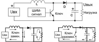
Before arriving at the floor specified by the passenger, the cabin must move at a stopping speed. Its value is reduced compared to the working value in order to eliminate a sudden stop that poses danger or discomfort to passengers. Old-style elevators have two speed settings. The elevator travels the main part of the route at the operating speed, and before stopping it switches to the stopping speed. Modern models use smooth adjustment using frequency electronic regulators. They smoothly increase engine speed at start and smoothly reduce them before the cabin stops. This mode is more comfortable for passengers. In addition, wear is reduced and engine life is increased.
Load capacity is the maximum permissible weight of the cargo transported in the elevator according to the passport. This value is indicated without taking into account the dead weight of the cabin itself and its additional equipment. The carrying capacity of standard passenger models is usually 400 kg. Passenger models of elevators with increased load capacity are widely used to equip new residential complexes. Thus, popular models are those that can operate with a load of up to 630 kg. Freight-passenger elevators are usually adapted for loads of up to 1 ton, and freight elevators - up to 5 tons.
Operating principle of the elevator
The elevator car is attached to strong steel cables that wrap around a grooved wheel or pulley. This drive mechanism is needed in order to redistribute force.
The signals are transmitted via an electrical cable to the engine room, which is located at the top of the shaft. To be precise, the cable connects the control cabinet below and the keypad in the cab.
The cables at one end have counterweights necessary to balance the elevator car. Once the engine starts, the weights are lowered, raising the platform (and vice versa). To lift the cabin, you don’t need a lot of power, since the main load goes directly to the counterweights.
What determines the lifting capacity of an elevator? The weight that the platform can lift depends on the power of the cable and the strength of its adhesion to the pulley. The equipment of freight elevators differs from passenger cars, first of all, in that there is another cable, that is, the drive wheel is wrapped twice.
Geared Elevators and Worm Gear
Lifts that are equipped with lifting machines may have a gearbox. If the elevator circuit provides a mechanism responsible for transmitting and converting torque, then we are talking about the so-called “worm gear”.
This means that the movement of the shaft is converted into the movement of the wheel. Mechanisms with a translational-rotational operating principle are used in cases where the loads being lifted are small and the distance covered by the platform is short. Typically, the installation of elevators of this type is ordered for cottages, small hotels, boarding houses, and so on.
What is the difference between a lift and an elevator?
Few people know that a lift differs from an elevator only in the design of its doors. So, the elevator has double doors, and the elevator has single doors.
Passengers sometimes complain that elevator doors take too long or too quickly to close. This means that the time relay is not configured correctly.
Next, let's talk about security. Elevator equipment includes a brake, which must fix the counterweights and the cabin. If the cables become loose or break, the platform should be blocked.
In an emergency, catchers connected by ropes to a limiting device at the bottom of the shaft, in the elevator pit, are activated. The catchers also replace the brake if the cab exceeds the set speed.
Elevator design
Modern buildings can use different types of lifting devices. At the same time, the overall design of the elevator does not fundamentally change. It includes the following nodes and elements:
- cabin (in the case of a cargo model - platform);
- a counterweight necessary to balance the cabin;
- high-strength steel cables;
- rotating pulley system;
- drive and control equipment;
- profile guides along which the cabin moves;
- safety system.
The cabin is suspended on steel ropes thrown over pulleys. A counterweight is suspended from opposite ends of the ropes. The required number of cables and pulleys used is calculated depending on the weight of the cabin and balancing weights, the lifting capacity of the elevator equipment and other factors. The drive mechanism (usually an electric motor) rotates the pulleys when commanded by the control system. As a result, the elevator car is lowered or raised, depending on the direction of rotation of the pulley system. In this case, the counterweight moves in the opposite direction.
The use of a counterweight can significantly reduce the power of the electric motor, since most of the work of raising or lowering the elevator is done due to gravity. Movement is carried out along vertical guides made of high-strength steel profiles. This eliminates the cabin from rocking and moving when raising or lowering - it moves strictly vertically.
A machine room is equipped in the building to accommodate the drive mechanism and control system. The drive is based on an asynchronous electric motor. Rotation is transmitted to the pulleys at a given frequency through a transmission mechanism. The control equipment is located in the installation cabinet. Connection between the control system and the panel installed in the cabin is ensured using a flexible cable. The controls are also located on the duty operator's console.
How does the elevator work?
In general, the main object of the elevator is the cabin itself. However, for the elevator to fully operate, it also requires a shaft along which the elevator car moves. The elevator shaft is not empty - on each side of the cabin there is an analogue of rails on which the elevator rides. If these rails were not there, the cabin would rise unevenly, sway and hit the walls of the shaft. In addition, at the very bottom of the shaft there is a so-called pit, a place where the cabin can fall if the cables break. Special springs are often installed here, which are ready to soften the fall of the lift cabin.
The elevator car has two doors: the first are internal, which travel along with the elevator itself. The outer doors remain motionless. They are installed on each floor where the elevator stops and only open in tandem with the internal doors. There is a control panel installed in the middle of the cabin, thanks to which the passenger gives commands to the elevator, sending it to the desired floor, etc.
The elevator car rises and lowers on metal cables - in total, the car is usually lifted from three to seven cables, each of which has an extreme load capacity. If one or even two elevator cables break, the cabin will not fall, but will be supported by the remaining ones. For the safety of the lifting mechanism, each cable individually is able to withstand the weight of the maximum filled elevator.
In order for the elevator to rise and fall, it must be pulled. In ancient times, this function was performed by people, then by animals, after which the job was transferred to engines. The first engine was a steam engine, then a hydraulic one was created, but today the entire task is carried out by an electric motor. The large rope pulley is a wheel that winds the cable around itself when the cabin is raised and unwinds it when the elevator descends.