Added March 5, 2022 at 10:15 pm
Save or share
If you've ever blown up a water heater or ever tried to make submersible electronics, you know how important it is to determine if there is water around. This water level sensor makes it very easy!
This sensor can be used to measure water level, monitor a septic tank, detect rain or detect leaks.
How a water level sensor works and its interaction with Arduino
Hardware overview
This sensor contains a series of ten open copper traces, five of which are power and five are sensitive.
These tracks are interleaved so that between every two supply tracks there is one sensing track.
Usually these paths are not connected to each other, but when immersed they are connected by water.
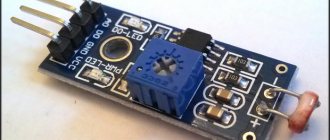
Figure 1 – Water level sensor
There is a power indicator on the board that lights up when power is applied to the board.
How does a water level sensor work?
The operation of the water level sensor is quite simple.
A series of open parallel conductors together act as a variable resistor (potentiometer), the resistance of which changes depending on the water level.
The change in resistance corresponds to the distance from the top of the sensor to the surface of the water.
Figure 2 – Demonstration of the operation of the water level sensor
Resistance is inversely proportional to water height:
- the more water the sensor is immersed in, the better the conductivity and the lower the resistance;
- The less water in which the sensor is immersed, the worse the conductivity and the higher the resistance.
The sensor, in accordance with the resistance, produces an output voltage, by measuring which we can determine the water level.
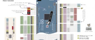
Water level sensor pinout
This water level sensor is very easy to use and has only 3 pins for connection.
Figure 3 – Pinout of the water level sensor
The S (Signal) pin is an analog output that will be connected to one of the analog inputs of your Arduino board.
The + (VCC) pin provides power to the sensor. It is recommended to power the sensor with a voltage of 3.3 to 5 V. Please note that the voltage at the analog output will depend on what supply voltage is supplied to the sensor.
— (GND) – ground.
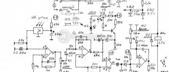
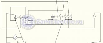
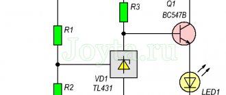
Principle of operation
The circuit diagram of a self-made water level switch is very simple. When the septic tank is not yet filled, the float is in the lower position, and the neodymium magnet is opposite the first reed switch. In this position, the reed switch contacts will be forcibly closed to pin 3, through which the electric current is directed to the green light bulb.
As soon as the tank is filled, but the liquid level has not yet reached critical values, the float will rise slightly and the effect of the magnetic field on the contacts of the first reed switch will stop. In this position, the “standby” mode will be activated, in which both reed switches will operate in a state where the current through them passes to contact 2.
After the liquid level in the tank rises, the float will move upward, and the neodymium magnet will align with the second reed switch, in which the contacts will switch to contact 3, through which electric current will flow to the red LED.
Connecting a water level sensor with Arduino
Let's connect the water level sensor to Arduino.
First you need to apply power to the sensor. To do this, you can connect the +(VCC) pin on the module to the 5V pin on the Arduino, and the -(GND) pin of the module to the GND pin of the Arduino.
However, one of the well-known problems with these sensors is their short lifespan when exposed to humid environments. By continuously supplying power to the probe, the corrosion rate increases significantly.
To overcome this problem, we recommend not constantly powering the sensor, but only turning it on when you are taking readings.
The easiest way to do this is to connect the VCC pin to the Arduino digital pin and set it to high or low when needed. So let's connect the VCC pin of the module to digital pin 7 of the Arduino.
Finally, connect the S (Signal) pin to the A0 pin of the Arduino A/D converter.
The connection diagram is shown in the following figure.
Figure 4 – Connection diagram of the water level sensor to Arduino
Materials required for the sensor
- 2 4093 chips;
- 2 sockets for microcircuits;
- 7 x 500 ohm resistors;
- 7 x 2.2 MΩ resistors;
- battery 9 V;
- battery socket;
- circuit board 10 x 5 cm;
- 8 brass sensor screws;
- double-sided tape or screws for attaching the box to the wall;
- network cable. The length of the cable depends on the distance from the water tank to the location where the display will be located.
So the base is CI4093, which has four elements. This project uses two chips. Here we have ports with one input at a high level, and the others connected through a resistor, providing a high logic level. By placing a zero input signal into this logic, the inverter output will go high and turn on the LED. A total of seven out of eight elements were used due to cable network limitations.
On the side there is a line of LEDs of different colors indicating the water level. Red indicators - there is very little water, yellow - the tank is half empty, green - full. The central large button is used to connect the pump and inflate the tank.
The circuit only works when you press the center button. The rest of the time she is in standby mode. But even when the indication circuit is triggered, the current is minimal and the battery will last for a long time.
Basic example of water level detection
Once the circuit is assembled, upload the following sketch to the Arduino.
// Pins connected to the sensor #define sensorPower 7 #define sensorPin A0 // Variable for storing the water level value int val = 0; void setup() { // Set up D7 for output pinMode(sensorPower, OUTPUT); // Set the level low so that no power is supplied to the sensor digitalWrite(sensorPower, LOW); Serial.begin(9600); } void loop() { // get the reading from the function below and print it int level = readSensor(); Serial.print("Water level: "); Serial.println(level); delay(1000); } // This function is used to get readings int readSensor() { digitalWrite(sensorPower, HIGH); // Enable sensor delay(10); // Wait 10 milliseconds int val = analogRead(sensorPin); // Read the analog value from the sensor digitalWrite(sensorPower, LOW); // Turn off the sensor return val; // Return current reading }
Once the sketch is uploaded, open the serial port monitor window to see the Arduino output. You should see a value of 0 when the sensor is not touching anything. To see how water is detected, you can take a glass of water and slowly immerse the sensor in it.
Figure 5 – Displaying water level sensor readings
The sensor is not designed to be fully immersed, so be careful when experimenting to ensure that only the exposed traces on the circuit board come into contact with water.
Explanation
The sketch begins by declaring the Arduino pins to which the + (VCC) and S (signal) pins of the sensor are connected.
#define sensorPower 7 #define sensorPin A0
Next, we define the variable val, which stores the current value of the water level.
int val = 0;
Now in the setup() function we first configure the pin to power the sensor as an output and then set it to a low logic level so that no power is supplied to the sensor initially. We also set up serial communication with the computer.
pinMode(sensorPower, OUTPUT); digitalWrite(sensorPower, LOW); Serial.begin(9600);
In the loop() function, we periodically call the readSensor() function at one second intervals and print the return value.
int level = readSensor(); Serial.print("Water level: "); Serial.println(level); delay(1000);
The readSensor() function is used to get the current water level. It turns on the sensor, waits 10 milliseconds, reads the analog value from the sensor, turns off the sensor, and then returns the analog value.
int readSensor() { digitalWrite(sensorPower, HIGH); // Enable sensor delay(10); // Wait 10 milliseconds int val = analogRead(sensorPin); // Read the analog value from the sensor digitalWrite(sensorPower, LOW); // Turn off the sensor return val; // Return current reading }
Testing the project's operation
Once the hardware of the project is ready, connect the Arduino board to your computer (laptop) and upload the program code to the Arduino board. Open the Serial Communication Monitor window at 9600 baud. Place an object in front of the ultrasonic sensor, the calculated distance to it will be displayed in the serial communication monitor window and on the LCD screen.
You can watch the project in more detail in the video at the end of the article.
Calibration
To get accurate readings from your water level sensor, it is recommended that you first calibrate it for the specific type of water you plan to monitor.
As you know, pure water does not conduct electricity. In fact, it is minerals and impurities that make it conductive. So your sensor may be more or less sensitive depending on the type of water you use.
Before you start monitoring data or running any event handlers, you need to see what readings you're actually getting from your sensor.
Using the sketch above, note what values your sensor produces when it is completely dry, when it is partially submerged, and when it is completely submerged.
For example, using the same circuit as above, you will see values similar to the following in the serial port monitor:
- when sensor is dry: 0;
- when it is partially immersed in water: ~420;
- when it is completely immersed: ~520.
Figure 6 - Water Level Sensor Calibration
This test may require some trial and error. Once you have good control over these readings, you can use them as thresholds if you intend to initiate any action. In the next example, we're going to do just that.
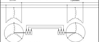
Electrical diagram for connecting the module
Typical electrical circuit for operation from a 5 V power supply.
The cable protrudes from the sealed sensor assembly and has a small 4-pin (2-pair) wire connector at the end. One pair of these wires is connected to the LED (light emitter) inside, and the other is connected to the phototransistor (light receiver). Here is a typical connection diagram for an optical liquid level sensor.
Although the diagram above gives a general idea of the connections, we recommend checking the color code of the wires before testing, as incorrect connections may damage the electronics.
Water level determination project
For our next example, we're going to create a portable water level sensor that will light up LEDs based on the water level.
Connection diagram
We will use the diagram from the previous example. But this time we just need to add some LEDs.
Connect three LEDs to digital pins 2, 3 and 4 via 220 ohm current limiting resistors.
Assemble the circuit as shown below:
Figure 7 – Water level indication using LEDs
Arduino code
Once the circuit is assembled, upload the following sketch to the Arduino.
In this sketch, two variables are declared, namely lowerThreshold and upperThreshold. These variables represent our threshold levels.
Anything below the lower threshold turns on the red LED. Anything above the upper threshold turns on the green LED. Everything in between turns on the yellow LED.
/* Change these values based on your calibration values */ int lowerThreshold = 420; int upperThreshold = 520; // Pins connected to the sensor #define sensorPower 7 #define sensorPin A0 // Variable for storing the water level value int val = 0; //Declare the pins to which the LEDs are connected int redLED = 2; int yellowLED = 3; int greenLED = 4; void setup() { Serial.begin(9600); pinMode(sensorPower, OUTPUT); digitalWrite(sensorPower, LOW); // Configure the LED pins to output pinMode(redLED, OUTPUT); pinMode(yellowLED, OUTPUT); pinMode(greenLED, OUTPUT); // Initially turn off all LEDs digitalWrite(redLED, LOW); digitalWrite(yellowLED, LOW); digitalWrite(greenLED, LOW); } void loop() { int level = readSensor(); if (level == 0) { Serial.println("Water Level: Empty"); digitalWrite(redLED, LOW); digitalWrite(yellowLED, LOW); digitalWrite(greenLED, LOW); } else if (level > 0 && level <= lowerThreshold) { Serial.println("Water Level: Low"); digitalWrite(redLED, HIGH); digitalWrite(yellowLED, LOW); digitalWrite(greenLED, LOW); } else if (level > lowerThreshold && level <= upperThreshold) { Serial.println("Water Level: Medium"); digitalWrite(redLED, LOW); digitalWrite(yellowLED, HIGH); digitalWrite(greenLED, LOW); } else if (level > upperThreshold) { Serial.println("Water Level: High"); digitalWrite(redLED, LOW); digitalWrite(yellowLED, LOW); digitalWrite(greenLED, HIGH); } delay(1000); } // This function is used to get readings int readSensor() { digitalWrite(sensorPower, HIGH); delay(10); val = analogRead(sensorPin); digitalWrite(sensorPower, LOW); return val; }
Original article:
- How Water Level Sensor Works and Interface it with Arduino
Squeaker for filtered water level signaling
Several factors prompted me to write this article.
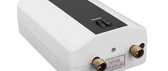
Even though I am an elderly person, I still use drinking water. In the city it is not recommended to drink tap water. When my son was renovating the kitchen with the replacement of kitchen furniture, a filter with replaceable modules (lifetime 8000 liters) was installed. I won’t mention the brand so that there is no advertising, but I will tell you the appearance.
Filtration system. View from below.
Filtration system. View from above.
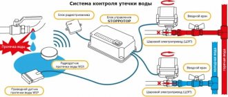
Water drips into a 5-liter bottle. Although the filter data sheet indicates a recommended filtration rate of 2.5 l/min, I deliberately dose in drops for two reasons.
- The completeness/degree of Ф is proportional to the time of contact of flowing water with the surface of the sorbent.
- At the same time, the water consumption is below the sensitivity threshold of the water meter (see “View from below”) and I get clean water for nothing (I do everything legally, and all claims are against the water meter manufacturer)!
Yes, the drop by drop process is not fast. Who is rushing the pensioner? Sit, watch TV or do crossword puzzles!
Like all older people, I suffer from minute-by-minute/instantaneous forgetfulness (there’s even a scientific name for this) - I put on a filter, went to watch TV and forgot, fell asleep. Time passes, but the bottle is full and overflowing!
Happened more than once! So I decided to install a high water level alarm on the filter. There are ready-made alarms, for example, for a baby’s wet diapers; I went shopping and couldn’t find them.