Automation protective equipment in electrical circuits protects people from electric shock and prevents the impact of network disturbances on connected equipment. Some devices are similar in their functionality and cause a lot of controversy between users about giving preference to one of them. Such devices include residual current devices (RCDs) and automatic circuit breakers. What they have in common, what are the differences, and what advantages do certain products have, is outlined in this article.
Functional differences between devices
Initially, you should figure out what the device names mean:
- the second name of RCD is differential switch (VD);
- abbreviation of difavtomat AVDT - “A” automatic “B” switch “D” differential “T” current.
In both cases, the concept of “differential current” is present, that is, leakage current. It appears when the electrical parts of the equipment are shorted to the housing and can lead to injury to a person or a fire. RCDs and RCBOs protect against such manifestations by turning off the power supply when they are detected.
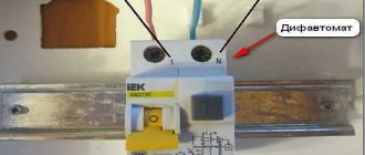
Appearance of RCD and RCBO devices (difavtomat)
The difference between them is that in addition to responding to leakage current, the difavtomat turns off the voltage when significant overloads or short circuits occur. RCDs do not do this, therefore, to protect against short circuits, in circuits using them it is necessary to additionally install automatic circuit breakers (AB), which are connected in series .
Let's summarize today's conversation
When choosing protective devices for your home power network, you should be very careful. Before going to the store, you need to decide what equipment will be installed in the distribution cabinet. While near the counter, you need to carefully study the markings on the device body so as not to buy a residual current circuit breaker instead of an RCD and vice versa. It makes sense to familiarize yourself with the certificates and approvals for protective equipment, which the seller must have. But in the end, no matter what the home master chooses, RCD or RCBO, the main thing is that the device efficiently performs the required functions to protect not only the network, but also the life of the owner.
Design differences of automation equipment
The schematic diagrams of the internal structure of the protective equipment under consideration have much in common, but differ in the presence of individual elements that determine their functionality. To better understand the operating principle of devices, you need to familiarize yourself with their designs.
The first one shown is the residual current device. It consists of three parts:
- a module in which the analysis of the current passing through the phase wire and returning through the neutral conductor takes place;
- an executive relay that is triggered when discrepancies are detected in the current values at the consumer input and at its output;
- test part, which serves to check the functionality of the device.
Schematic diagram of an RCD indicating the main design elements.
Three-phase devices control the equality between the sum of the current values of each phase and the current flowing through the neutral conductor.
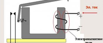
The design of the difavtomat, in addition to elements similar to the RCD, provides for the presence of additional releases that respond to changes in temperature and electromagnetic field. This can be seen in the following image.
Schematic diagram of RCBO with thermal and electromagnetic release
The thermal element of the difavtomat is triggered when the equipment is overloaded, and the electromagnetic element is triggered when overcurrents occur due to a short circuit. Thus, the RCBO provides protection both from leakage currents and from emergency modes.
Differential automatic: electromechanical, electronic, technical characteristics
What is a circuit breaker?
A device that protects electrical wiring and electrical appliances from short circuits and overloads. What is an RCD? This is another device that responds to leakage current that occurs when insulation deteriorates or a person touches live parts. These devices operate on different principles, but are united by one task: to protect electrical equipment and consumers from problems that arise during accidents in the electrical network. They are installed in distribution or group panels; cable lines leading to sockets are connected to them.
Cable lines are always protected from short circuits and overloads. But if it is necessary to provide protection against leakage, it is necessary to install an RCD as an additional protective device.
Connecting RCD and circuit breaker
The PUE obliges the installation of an RCD in the following cases:
- when consumers (sockets) are outdoors (on the street);
- to protect sockets and consumers in high-risk areas (bathrooms, showers);
- in cases where circuit breakers cannot effectively protect due to low short-circuit currents.
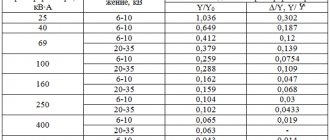
The last point requires some clarification. The further the consumer is from the power source (transformer at the substation), the greater the length of the electrical wiring between them.
Conductors have electrical resistance, so it increases between the source and the receiver.
During a short circuit, the current passing through the electrical wiring is limited by the small internal resistance of the source (the resistance of the secondary winding of the transformer) and the equivalent resistance of the conductors between the short circuit point and the source.
Therefore, the magnitude of the short circuit current decreases with increasing distance from the substation. At remote points, it is possible that the machine will not sense this current.
Of course, with a time delay its thermal protection will work. But if there is a short circuit to the housing connected to the PE bus of the shield, for this time it will be under a life-threatening potential.
This cannot be allowed; this is why the PUE prescribes the protection of such RCD consumers.
The PUE prohibits the installation of an RCD without installing a circuit breaker in series with it . Therefore, when using differential protection, the cable line is protected by two devices. Additional wires appear in the shield, its complexity increases slightly. In addition, the RCD also takes up additional space on the DIN rail. What if it’s already missing?
Differential automatic
To simplify the design of distribution panels and compact placement of elements inside them, differential circuit breakers are used. Their housing contains protection devices against short circuits, overloads, and leakage currents. In essence, this is a circuit breaker and an RCD in one housing.
Technical characteristics of differential automatic machines
A differential automatic machine has technical characteristics characteristic of both automatic machines and RCDs.
Rated current . It means the maximum possible current that the contact system of the device can pass without damaging it. The same value is used to calculate other characteristics of the device.
Cut-off response characteristics . The most common:
| Type C | 5-10 rated currents |
| Type D | 2-5 rated currents |
It is marked by applying the corresponding letter before the number indicating the rated current.
Marking of rated current and characteristics of the difavtomat
Example:
C40 – the rated current of the difavtomat is 40 A, the cutoff operates within the range (5-10)∙40 = 200-400 A.
The current value for a particular device lies in this range. It can only be known by measuring it using devices capable of producing and measuring such currents.
Residual current marking
Differential operating current . Takes values:
| Scale of differential currents of difavtomats, mA | ||||
| to protect outgoing lines | for introductory and group dial machines | |||
| 10 | 30 | 100 | 300 | 500 |
This figure is the upper ceiling of the leakage current value at which the difautomatic device will operate. The real current is measured by special devices that simulate the occurrence of difcurrent and measure its values at the moment of operation.
Type of residual current device . Marked with a letter index or a picture.
Marking of types of automatic devices and RCDs
It means to which shape of the current waveform the circuit breaker reacts.
| Marking | Current waveform | Application |
| AC | Sine wave only | Heating devices. |
| A | Sine and pulsating constant | Electronic household appliances, washing machines |
| IN | Sine wave, pulsating, constant smoothed | Industrial semiconductor devices |
Just like RCDs, differential circuit breakers are also selective. They differ from conventional ones only in the presence of a time delay for shutdown and increased electrodynamic stability.
Selective automatic devices are used as introductory protective devices. They need a time delay to allow the devices connected after the input to turn off the differential current.
If this does not happen, the selective machine is triggered. Electrodynamic stability is the maximum short circuit current that a device can withstand without damage.
For selective automatic circuit breakers, it is increased so that they can easily withstand long-term emergency modes with high currents.
note
Selective automatic devices are marked with letters, depending on the response delay.
| Letter designation | Response delay, ms |
| Type S | 200 – 300 |
| Type G | 60 – 80 |
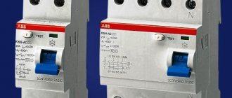
Electromechanical or electronic – which is better?
By analogy with RCDs, difavtomats are manufactured either with an electromechanical residual current device or with an electronic one.
The electromechanical device does not require additional power supply to operate. The energy to activate the trip coil, which removes the automatic device from the on state, is taken from the source of the leakage current.
Therefore, the differential transformer that registers these currents in electromechanical devices has large dimensions.
Its task is not only to sense the leak, but also to convert its small value into a voltage sufficient to trigger the device.
The large dimensions of the transformer increase the size of the device as a whole. Therefore, the volume they occupy in the panel is greater than that of electronic ones .
Electronic automatic devices, in addition to a leakage current sensor and a tripping coil, contain an electronic circuit with a signal amplifier. A small signal from the sensor increases to an amplitude and power sufficient to operate the release coil.
These automatic machines are more compact, but does that mean they are better? In fact, their advantages are limited to compactness. There are situations in which this device will not help.
If the supply line zero is interrupted, differential circuit breakers and RCDs with an electronic control circuit become useless . The power supply to the electronics disappears, it does not work and is not able to turn off the device. And the need for this at such moments is more than relevant.
When neutral conductors in networks break, voltage values are redistributed between phases. On phases with a higher load, the voltage decreases. The worst thing is that on unloaded phases the voltage can increase up to 380 V inclusive.
Whether the difavtomat will endure such a regime or not is a moot point.
Important
And the result of this mode of operation can be insulation breakdowns on the casings of electrical appliances, which is what difautomats and RCDs are designed to eliminate and localize. If they are semiconductor, then you should not expect a reaction from them.
Product marking by operating current value
Each device is designed to operate under rated load, that is, it is capable of passing current and voltage of a certain value. The manufacturer makes a corresponding entry about this on the front panel of the case. However, for a difavtomat, the rated current is set depending on the type and characteristics of the thermal and electromagnetic releases, therefore it is always indicated accompanied by the Latin letter “C”, “B” or “D”.
Thus, on an RCD, a rated current of 16 amperes is indicated as 16A, and the same indicator on a RCBO will look like C16.
Trip characteristics of protective circuit breakers
Class AB, determined by this parameter, is indicated by a Latin letter and is marked on the body of the machine before the number corresponding to the rated current.
In accordance with the classification established by the PUE, circuit breakers are divided into several categories.
MA type machines
A distinctive feature of such devices is the absence of a thermal release. Devices of this class are installed in circuits connecting electric motors and other powerful units.
Class A devices
Type A machines, as was said, have the highest sensitivity. The thermal release in devices with time-current characteristic A most often trips when the current exceeds the nominal value AB by 30%.
The electromagnetic trip coil de-energizes the network for approximately 0.05 seconds if the electric current in the circuit exceeds the rated current by 100%. If for any reason, after doubling the electron flow, the electromagnetic solenoid does not work, the bimetallic release turns off the power within 20 - 30 seconds.
Automatic machines with time-current characteristic A are connected to lines during operation of which even short-term overloads are unacceptable. These include circuits with semiconductor elements included in them.
Class B protective devices
Devices of category B are less sensitive than those of type A. The electromagnetic release in them is triggered when the rated current is exceeded by 200%, and the response time is 0.015 seconds. Triggering of a bimetallic plate in a breaker with characteristic B at a similar excess of the AB rating takes 4-5 seconds.
Equipment of this type is intended for installation in lines that include sockets, lighting devices and other circuits where there is no starting increase in electric current or is of minimal value.
Category C machines
Type C devices are the most common in household networks. Their overload capacity is even higher than those previously described. In order for the electromagnetic release solenoid installed in such a device to operate, it is necessary that the flow of electrons passing through it exceeds the nominal value by 5 times. When the thermal release is exceeded five times the nominal value of the protection device, the thermal release is triggered within 1.5 seconds.
Installation of circuit breakers with time-current characteristic C, as we said, is usually carried out in household networks. They do an excellent job as input devices to protect the general network, while category B devices are well suited for individual branches to which groups of sockets and lighting fixtures are connected.
Circuit breakers category D
These devices have the highest overload capacity. To trigger the electromagnetic coil installed in a device of this type, it is necessary that the electric current rating of the circuit breaker be exceeded by at least 10 times.
In this case, the thermal release is activated after 0.4 seconds.
Devices with characteristic D are most often used in general networks of buildings and structures, where they play a backup role. They are triggered if there is no timely power outage by circuit breakers in individual rooms. They are also installed in circuits with large starting currents, to which, for example, electric motors are connected.
Protective devices categories K and Z
These types of machines are much less common than those described above. Type K devices have a large variation in the current required for electromagnetic tripping. So, for an alternating current circuit this indicator should exceed the nominal value by 12 times, and for a direct current circuit - by 18. The electromagnetic solenoid operates in no more than 0.02 seconds. Triggering of the thermal release in such equipment can occur when the rated current is exceeded by only 5%.
These features determine the use of type K devices in circuits with exclusively inductive loads.
Devices of type Z also have different actuation currents of the electromagnetic tripping solenoid, but the spread is not as great as in AB category K. In AC circuits, to turn them off, the current rating must be exceeded three times, and in DC networks, the value of the electric current must be in 4.5 times more than nominal.
Devices with Z characteristic are used only in lines to which electronic devices are connected.
Visually about the categories of machines in the video:
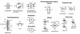
Device diagram
Most models have an image of their circuit diagram on the body. The presence of a thermal and electromagnetic release designation on it indicates that the device is a difautomatic device. They look similar to the following images:
Schematic designation of thermal and electromagnetic releases
Knowing about the listed distinctive features, you can easily determine which device is installed in a particular circuit. One or more of them will definitely be obvious .
Visual differences between RCD and RCBO
RCD and difavtomat: designation on the diagram
It’s quite strange, but GOST does not give any explanations as to what the residual current device should look like on the diagram. Most often, each electrician marks such a device in his own way. Over the years, a certain generally accepted image has developed (it can be seen below), which is used with certain deviations. Even if you pay attention to the devices themselves, the schematic images on the housings of devices from different brands differ.
GOST also does not provide for specific rules for the designation of a residual current circuit breaker. Such an omission causes a lot of problems in reading diagrams as a result of misunderstanding - after all, every electrician believes that the image he made is the only correct one. Below you can see the generally accepted image. It’s not a fact that in the diagram you get your hands on it will be absolutely identical, but it will be possible to catch the general idea. This will make it a little easier to understand what exactly is installed in a particular distribution cabinet.
After familiarizing yourself with the generally accepted schematic images, it becomes clear how to distinguish an RCD from a difavtomat when reading projects.
Connection diagrams for protective devices
An RCD cannot protect itself and the network to which it is connected from overloads and short circuits, therefore it requires the use of circuit breakers as additional protection.
Single-level diagram for connecting an RCD to a household electrical network
In this case, the device is group and controls all the electrical wiring of the house. To control each individual powerful consumer of electricity (boiler, stove, convector), its own RCD can be connected to its circuit in series with the circuit breaker.
Differential automatic machines are installed after the metering device (electricity meter) subject to certain conditions:
- It is not allowed to connect RCBOs in series with each other;
- You cannot use neutral conductors coming from other devices (phase and zero are taken from only one difautomatic device);
- It is prohibited to combine output zeros for subsequent distribution.
Connection diagram for difavtomats in a household electrical network
Operating principle
An RCD in a single-phase network is carried out as follows. A differential transformer has three windings: one is connected to the phase wire, the other to the neutral wire, and the third one records the current difference. When connected, the first and second windings must have opposite current directions. In normal network operating mode, they will be equal to each other. Under their influence, magnetic fluxes directed towards each other are induced in the magnetic circuit of the transformer. The sum of the magnetic fluxes is zero, so there is no current in the third winding.
When a fault occurs in an electrical appliance, phase voltage appears on its body. Therefore, in case of touching a metal case, a person begins to be affected by current leakage flowing through his body to the ground. In this regard, a current difference will appear in the first and second windings of the transformer, and magnetic fluxes of different magnitudes will be induced in the magnetic circuit.
As a result, the total magnetic flux will differ from zero and will cause a current with some value to be induced in the third winding, which is called differential. When this current reaches the triggering threshold, the residual current device will also trigger.
The operating principle of an RCD in a three-phase network is almost the same as in a single-phase one. A differential transformer is also used here, comparing not one, but three phases and the neutral wire. Consequently, the transformer of a three-phase protective device has five windings: three phase, one neutral and one secondary, which detects current leaks.
In addition to the main structural elements, the RCD includes a testing mechanism consisting of a resistor connected through the TEST button to the transformer winding. After pressing the button, the resistor is connected to the winding. Due to this, a current difference is created that flows to the secondary winding and causes the protective device to trip. Normal operation indicates the functionality of the protective device.
Advantages and disadvantages of VD and RCBO
At first glance, it may seem that the advantages of difavtomats over RCDs are completely obvious. But one should not draw hasty conclusions. It is not without reason that well-known brands – manufacturers of automation equipment – produce both types of protective devices, which are in equal demand.
For a fair assessment, the reader is invited to make a comparative analysis of the advantages and disadvantages of both devices, summarized in tables for ease of perception:
- When using RCD
| Advantages | Flaws |
| When disconnected, you can easily determine the reason (AV or VD triggered) | Needs an additional short circuit protective device |
| In the event of a breakdown, only one of the devices (AV or VD) must be replaced. | Due to the need to use AV, the price increases |
| You can use one RCD with several machines | Takes up more space in the electrical panel |
- When using a automatic machine
| Advantages | Flaws |
| One device combines the functions of an RCD and a circuit breaker | Difficult to determine the cause of the operation |
| Places more compactly in the electrical panel | If damaged, must be completely replaced |
| Has a lower cost than the total price of the VD and the machine |
As you can see, each of the devices can be used with equal success. In some cases, it is more convenient to use a RCBO, in other situations it is more profitable to install an RCD. The final decision remains with the user .
RCD installation
The installation of an RCD should only be entrusted to a qualified electrician, since the robot has a high risk of electric shock.
When choosing a location for installing an RCD, you should take into account areas of the electrical circuit with the highest risk of electric shock (bathroom, kitchen). To increase electrical safety, it is recommended to install a separate RCD on each branch of the circuit, power the kitchen, bathroom, bedroom, etc. separately; in this case, special group panels should be used during installation. When answering the question of how an RCD differs from a machine, it should be taken into account that one of them protects against current leaks, and the other against short circuits.