Rotor for INTERSKOL USHM-2300M, HAMMER. Photo 220Volt
When an angle grinder fails, diagnostics are performed to identify the causes . One of them may be a breakdown of the armature (rotor) of the electric drive. check the serviceability/failure of this rotating assembly yourself . It is necessary to have in your arsenal only simple devices for testing the electrical circuit.
Device
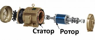
To correctly diagnose armature faults, it is important to know the device and the principle of its operation . The main elements of the armature are a round core, consisting of a set of electrical steel plates and a winding wound into its grooves in a certain way. Two armature windings are placed in each of the grooves according to a special pattern . The first and last turns of one of the windings are in the same groove and are closed to one lamella.
Rotor for Makita angle grinder 9069 MAX. Photo 220Volt
The core is pressed onto the rotor , which rotates under the influence of forces arising in the electromagnetic field formed by the armature windings and the stator coils working in tandem with it. In grinders, the anchor is an assembly unit with a drive gear located at one end of the shaft, and a commutator unit at the opposite end.
Repair: Elimination of insulation breakdown
If the insulation breakdown was small and you found it, you need to clean this place of carbon deposits and check the resistance. If its value is normal, insulate the wires with asbestos. Apply quick-drying “Super Moment” type glue on top. It will seep through the asbestos and insulate the wire perfectly.
If you have not found the location of the insulation breakdown, then try to carefully saturate the winding with impregnating electrical insulating varnish. Punched and unpierced insulation will be saturated with this varnish and become stronger. Dry the anchor in a gas oven at about 150 degrees. If this does not help, try to rewind the winding, or change the armature.
How to check the armature of an electric drill
The electric motor armature is not subject to wear under normal operating conditions. Only the brushes are replaced, measuring the permissible length. But under prolonged loads, the stator windings begin to heat up, which leads to the formation of carbon deposits.
Expert opinion
Viktor Pavlovich Strebizh, lighting and electrical expert
Any questions ask me, I will help!
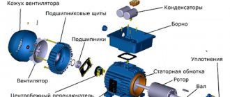
In addition to the coils wound into the grooves of the core, its assembly includes bearing units, a collector, a fan and the shaft itself. If there is something you don’t understand, write to me!
Causes of malfunctions
The causes of rotor failure may be improper operation of the power tool, which is represented by the following factors:
- the permissible time of continuous operation has been exceeded, which is one of the main reasons for the failure of household angle grinders;
- carrying out work in aggressive environments with the presence of sand, moisture, abrasive dust and other similar materials;
- work in conditions exceeding the permissible load;
- some mechanical faults affect the imbalance of the rotating rotor, which ultimately affects the normal functioning of the rotor electrical circuit;
- instability of the mains voltage while working with a power tool.
Serviceable rotor for Bosch angle grinder GWS6-100/GWS 850 MAX. Photo 220Volt
The operation of a power tool associated with the action of these factors leads to the following malfunctions :
- breakage of coil conductors;
- short circuit between turns due to burnt insulation;
- the insulation loses its properties, which can cause breakdown of the winding to the core body;
- violation of collector contacts;
- Particles of burnt insulating varnish or melted solder that get into the gaps that come into contact with the rotating rotor can cause mechanical damage to the elements of the angle grinder: cracks, chips, deep scratches.
- The collector lamellas wear out unevenly and carbon deposits form on them due to a short circuit.
This mainly happens when the grinder's commutator engine operates for a long time without a rest break. The winding insulation from heating loses its characteristics and melts, which leads to a short circuit of the turns. The contacts connecting the armature winding to the commutator lamellas can become unsoldered, the electric current is interrupted and the electric drive stops.
Checking the stator with a multimeter
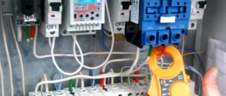
The electrostator is located on the outer portion of the electric motor, on top of the rotor. Before checking the stator, you need to dismantle it and remove the brushes, and then remove the gearbox. First, carefully inspect the winding and make sure that there are no visible breaks or other defects on its surface.
Possible causes and signs of a non-working angle grinder stator:
- A sharp increase in voltage;
- penetration of moisture into the engine;
- overload of power tools and created internal overheating of components;
- abruptly removing the cord from the outlet while the tool is running;
- the appearance of a smell of burnt rubber or plastic;
- case overheating;
- the appearance of smoke from the electric motor during its operation;
- slow rotation of the shaft or its complete absence;
- The grinder sharply picks up speed.
Important! When the protective coating on the winding wires overheats, the varnish melts, releasing a pungent odor, and the winding insulation is damaged. Short circuit of even one winding completely removes the tool from working condition.
The multimeter allows you to check for a break in the stator windings; to do this, you must perform the following steps:
- The meter is set to R mode to a maximum of 200 Ohms.
- They begin checking the error of the multimeter, to do this they touch the probes together, the tester arrows should point to “0”.
- Touch the probes to the terminals on the windings, if the instrument scale shows “infinity”, the winding is not working and rewinding is necessary.
- Check for the presence of a short circuit on the housing. A very dangerous condition of a power tool that not only causes a loss of power, but is also a potential source of electric shock to the user.
- Includes resistance measurement.
- The red probe is installed on the winding terminal, the black one is fixed on the stator housing.
- When the stator winding short-circuits to the housing, R on the display is less than on the working winding. This failure can only be eliminated by rewinding the windings.
- To measure an interturn short circuit in an electrostator, R is measured on a separate winding.
- Determine the “0” point of the windings by measuring R of each. The least resistance will indicate a faulty one.
A multimeter allows you to quite accurately determine malfunctions in the armature and stator of an angle grinder motor. A detected malfunction can be eliminated by rewinding the electric motor or replacing it from the repair kit. Currently, there are enough such sets in the retail chain for most popular models of angle grinders.
Important! When replacing faulty engine components, it is imperative to replace new brushes, especially since they are completely inexpensive.
After repairing the stator or rotor, the tool is reassembled using the saved disassembly photographs. Check the functionality of the tool. If everything is done correctly, the grinder will serve its owner for many more years.
How to check the serviceability and ring the rotor of an angle grinder at home, video
At home, there are the following methods for diagnosing an anchor:
- visual inspection;
- using a multimeter;
- a light bulb and two wires connected to it;
- devices specially designed for checking the integrity of windings (short circuit indicator, armature testing device and others).
For more information about the types of diagnostics, see the information below, where there is a video.
Visual inspection
Even if you have a full arsenal of instruments for testing the armature electrical circuit, never neglect a visual inspection - the mandatory first step of the entire diagnostic process. A careful look will find signs by which a user who knows the design and principles of operation of the rotor will determine the nature of the malfunction.
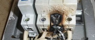
Charred marks and the presence of a specific odor cause burnt insulation and ultimately damage to the winding wires. You should pay attention to crumpled or swollen coils , which may indicate the presence of breaks in a given location. solder particles on , which can cause a short circuit.
Violations in the contacts of the windings with the collector can be detected by burnt out lamellas . Damage to the collector itself is visually diagnosed - raised, worn or burnt plates.
Tester, multimeter
The device multimeter or its other name is a tester for measuring electrical parameters: current, voltage, resistance - can be used to search for breaks in winding wires or breakdowns in the core body.
In the following video, the author offers a diagnostic option from simple to complex. Using a multimeter, the stator is first tested. It is much easier to check it than the rotor. If there are no breaks on the stator and no breakdowns of the winding to the housing, then we can conclude that the armature is faulty. Next, you should diagnose it in more detail, determining the exact type of defect and determining the method of elimination. A continuity test is carried out with a multimeter in the “resistance test” mode with the minimum measurement scale set (up to 200 Ohms).
This video, like the other, shows the process of determining winding breaks, which is really quite labor-intensive, since measurements are taken between each pair of lamellas along the entire contour of the collector. In this case, on an armature that does not have breaks in the windings, all multimeter readings should not differ from each other within 0.1 Ohm. It is much easier to check the breakdown of the windings on the body by placing one probe on the core body and the other on the collector plates. The multimeter scale should not respond with any readings.
It is impossible to determine the interturn short circuit with a multimeter. Other devices are used here.
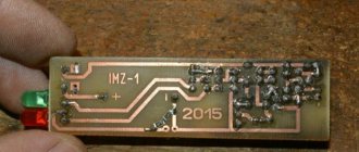
Interturn short circuit indicator
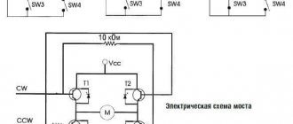
In the following video, the author tests a device for determining the interturn circuit (IMC) of his own making. The principle of its operation is based on the interaction of electromagnetic fields created by the coils of the IMZ device and the windings of the armature or stator. In the presence of an interturn short circuit, the parameters of the magnetic field of the device change, which is recorded by a light indication - the red light comes on, and if there is no short circuit, the green light lights up.
A light bulb
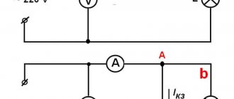
If you don’t have a multimeter, you can test the electrical circuit of the rotor using a 12 V light bulb. First , connect two wires to the light bulb itself. The power source is a regular battery, to the ends of which you should connect the ends of the break of one of the wires connected to the light bulb. Such an amateur “device” is used instead of a multimeter, where the ends of the wires are applied to the lamellas without touching each other. Carefully rotate the armature to monitor the brightness of the light bulb. If it is constantly on without blinking, then there are no breaks in the winding.
Breakdown of the winding to the core body is checked by connecting one of the ends to the collector and the other to the core or shaft. If the light comes on, it means there is a breakdown of the winding to the housing.
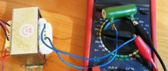
Throttle
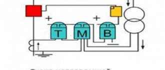
The presence of an interturn short circuit in the rotor can be determined using a device for testing armatures. It is a transformer with one primary winding ; in fact, it is a wire wound on a ferromagnetic core. At the same time, it has a triangle cutout in it, in which the rotor under test can be stably positioned. Its winding begins to work as a secondary coil of a transformer.
In the presence of an interturn short circuit, the parameters of the rotor magnetic field have greater intensity; a metal strip placed on the surface of the core will vibrate and, when magnetized, will be attracted to the core body. The plate will move freely on the rotor core body if it has normal windings without defects.
Winding faults and their elimination
Asynchronous motors
Asynchronous electric motors are widely used not only in industry (on machine tools, in compressors, pumps), but also in everyday life (in refrigerators, washing machines of some models). If they malfunction, a visual inspection should begin with the stator windings, which play the role of an armature.
Before ringing the armature of an electric motor, it is necessary to check other components and parts (since the reason may be their damage) - connection cables, magnetic starters, thermal relay, capacitor, and also check for the presence of voltage. If everything is ok, make sure there is no power supply and disassemble the motor.
The reasons why the stator windings stop working are most often the following:
In 220V electric motors, it is enough to ring the working and starting windings. The resistance of the first should be one and a half times lower than that of the second.
The most difficult stage of testing is searching for an interturn short circuit, since it is not possible to identify it during a visual inspection. You need to use a special inductance meter. If the value is the same on all windings, there are no problems. The lowest value on any winding indicates damage.
What kind of lighting do you prefer?
Built-in Chandelier
Now you know how to check the armature of an electric motor with a tester, and you can identify the cause of the problem without involving a specialist and eliminate it, saving money and time.
Repair, replacement, rewind
After diagnosing and determining the types of rotor faults, a decision on repair methods follows . It is possible to do the repair yourself, which will involve rewinding the armature yourself. If this option seems labor-intensive and complicated, you can follow a simplified scheme and replace the burnt out rotor with a new one that matches the model of the angle grinder. The simplest, but also expensive option is to contact a special service department .
When making a decision about repairing an anchor with your own hands, the information available in the articles “How to remove an anchor from an angle grinder”, “Replacing and repairing an angle grinder’s anchor”, “Rewinding an angle grinder’s anchor with your own hands” will help.
How to “revive” a faulty device?
Repair of the electric motor armature begins only after full confidence in the malfunction of the unit. Scratches and chips on the lamellas are removed by circular groove of the surface. Carbon deposits and soot can be removed with cleaning agents for contact electrical connections. Broken bearings are repressed and replaced with new ones. It is important to balance the shaft during assembly.
Rotation should be easy and without noise. Damaged insulation is restored; ordinary electrical tape can be used. It is better to solder connections that cause suspicion. If there are problems with the armature coils, it is recommended to resort to rewinding, which you can do yourself.
For what reasons can an angle grinder fail?
Most often, the tool stops working when the armature (rotor) is damaged. When opening the case, you can see burning and uneven wear of the brushes. Indirect signs of such a breakdown are heating of the tool and vibration during operation.
Electrical faults are more difficult to detect. These include:
- violation of the resistance between the winding and the core;
- damage to the armature winding;
- short circuits in turns.
Also quite common reasons for tool failure can be:
- a break in the wires in the power cable and a malfunction of the switch - the angle grinder does not turn on;
- an interturn short circuit in the rotor windings and an electronics malfunction lead to the fact that the tool only works at low speeds;
- sparking due to abrasion of carbon brushes or severe wear of the engine commutator;
- Smoke appears when there is a short circuit in the stator or rotor windings, as well as during excessively intense work (when the air cooling channels are clogged with dust).
As you can see, many breakdowns are caused by faults in the electrical part of the tool. Therefore, you need to be able to detect them before deciding to send the tool to a repair shop.
Detection of inter-turn short circuit
You can understand that the rotor turns may have shorted out not only by the sound and smell of the running engine, sparking on the brushes and its uneven heating. There are other ways to determine this malfunction. True, this is done with the electric motor disconnected from the network. These are the methods.
- visual inspection of the anchor;
- measuring the load on each rotor phase using current clamps;
- use of a special tester;
- use of a homemade throttle;
- check with a multimeter.
Checking the rotor for interturn short circuit with a multimeter will be discussed further. But before that, let’s briefly analyze the device and operating principle of the multimeter.