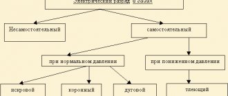
Air gap breakdown
Breakdown of the air gap is a consequence of impact ionization. The electric field strength at which impact ionization occurs, leading to the formation of electron avalanches, is called the initial strength.
Due to the different mobility of electrons and positive ions formed under the influence of impact ionization, a space charge appears in the gap, which distorts the electric field. With a further increase in the voltage applied to the gap, breakdown occurs, and the degree of inhomogeneity of the electric field has a significant influence on the breakdown voltage.
In the case of electrodes that form a nearly uniform electric field at small discharge gaps, the occurrence of impact ionization instantly leads to breakdown of the gap, that is, breakdown of air occurs without the development of processes complementing the breakdown. Under such conditions, the breakdown voltage coincides with the initial field strength.
A non-uniform electric field is characterized by the presence of three stages in the development of air breakdown. Compared to a uniform field, the initial voltage here is significantly lower. As a result of impact ionization, a corona discharge (local ionization) occurs in places with maximum field strength, accompanied by a glow. With increasing voltage, the corona discharge turns into a brush discharge, in which the glow is not concentrated around the electrode, but spreads in the form of separate beams emanating from one electrode, but not reaching the other. With a further increase in voltage, the brush discharge short-circuits both electrodes. A spark forms between the electrodes, indicating a complete breakdown of the air gap. If the power of the voltage source is sufficient, the spark turns into an electric arc. The development of the above processes leads to a noticeable decrease in the breakdown voltage of the air gap compared to a uniform electric field, all other things being equal.
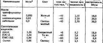
The electrical strength of air gaps depends not only on the degree of inhomogeneity of the electric field, but also on temperature, pressure and air humidity. For example, the amplitude value of the breakdown voltage Upr of air at a frequency of 50 Hz in a uniform field, MV, is determined by the empirical formula:
The greatest degree of electric field inhomogeneity is inherent in rod-plane and rod-rod systems.
Electrical breakdown
In air at atmospheric pressure, a voltage of 30 thousand V is needed to break a gap of 1 cm between balls with a radius also of 1 cm. Let's push the balls apart. You will have to apply a higher voltage to break through the air gap.
An analogy from mechanics involuntarily suggests itself. Air is pumped into a steel cylinder. He presses on the walls. If the pressure is very high, they can eventually rupture. The thicker the walls, the higher the pressure the cylinder can withstand. In electrical breakdown, it seems natural that a larger layer of air will withstand a greater voltage.
Instead of increasing the distance between the electrodes, you can increase the density of the air surrounding them by placing the electrodes in compressed gas. This will also increase the breakdown voltage.
In internal combustion engines, the mixture is ignited by an electric spark. A “spark plug” with two nickel electrodes is screwed into the engine cylinder at a distance of about a millimeter from one another. At atmospheric pressure, this gap between the electrodes breaks through at 3-5 square meters. And when the mixture in the cylinder is compressed, a voltage several times greater is required.
Different dependence of breakdown voltage on pressure and gap in electric vacuum devices. In thyratrons, for example, the gap between the grid and the anode is reduced in order to increase the breakdown voltage. In thyratrons, decreasing the distance increases the electrical strength of the device.
A breakdown of a gas gap develops as follows: there is always a certain amount of free electrons in the gap between the electrodes. When voltage is applied to the electrodes, electrons begin to move towards the positive electrode. On their way, these electrons can encounter neutral gas molecules. The distance between two such meetings, two collisions is called the free path of an electron. The free path depends on the density of the gas. At atmospheric pressure, the free path is tiny fractions of a millimeter. And at high vacuum the free path reaches several centimeters.
If an electron hits a neutral molecule at a high enough speed, it breaks it apart - knocks one or even several electrons out of it. These electrons, together with the initial ones, also move towards the positive electrode. On the way, they may encounter more neutral molecules and snatch more electrons from them. When the voltage between the electrodes is high enough, an electron avalanche occurs. A small initial number of electrons increases as a result of numerous collisions, like a snowball rolling down a mountain.
The appearance of an electron avalanche is a breakdown. When the gas density is high, an electron during the path between two collisions can accumulate enough energy to knock a new electron out of the molecule only at a high voltage between the electrodes. The higher the gas density, the higher the voltage at which an electron avalanche can form and breakdown will occur.
If the gas density is low and the free path of electrons is large, then a large number of them will fly between the electrodes without encountering gas molecules at all and without knocking out new electrons.
In this case, the lower the density of the gas or the smaller the distance between the electrodes, the greater the voltage is necessary to cause an avalanche of electrons and produce a breakdown.
In fig. Figure 7-22 shows an approximate curve of the breakdown voltage versus the product of gas density and the gap between the electrodes.
Fig. 7-22. Dependence of the breakdown voltage between two electrodes on the product of the density p of the gas surrounding the electrodes and the distance d between the electrodes.
The lowest breakdown voltage is obtained when the electron free path is of the same order of magnitude as the distance between the electrodes. The breakdown voltage increases in both cases: when the electron free path is significantly less than the distance between the electrodes (high pressure region) and when the electron free path is significantly greater than the distance between the electrodes (low pressure region).
The lowest voltage is required for breakdown when the distance between the electrodes is of the same order as the electron free path. Surge arresters are often used in electrical circuits. They act as safety valves. Their purpose is to be the weakest point in the electrical circuit. The design dimensions of the arresters are selected in such a way that they correspond to the minimum of the breakdown curve.
At atmospheric pressure, in order to obtain a low breakdown voltage, it is necessary to provide a gap of several microns between the electrodes of the spark gap. It is more convenient to place the spark gap electrodes in a flask with reduced pressure. Then the minimum breakdown voltage corresponds to a gap of several millimeters.
The minimum breakdown voltage can be 100-200 V. If you reduce the density of the gas surrounding the electrodes, the magnitude of the breakdown voltage will increase. In gastrons (Fig. 2-4) the distance between the cathode and anode is the same as in spark gaps, but in spark gaps the gas pressure in the cylinder is several millimeters of mercury, and in gastrons the pressure is only a few ten thousandths of a millimeter of mercury. The breakdown voltage of the gastron is about 20,000 V. With an even greater vacuum between the electrodes, the breakdown voltage increases to several hundred thousand volts.
Plateau instead of a peak
It happens that the maximum point is not clearly expressed.
During induction heating in a melting furnace (Fig.
7-9), or for surface hardening (hardening will be discussed in subsequent sections), it is important to obtain high efficiency. The alternating current circulating in the inductor creates a rapidly varying electromagnetic flux around its conductors. This flow penetrates the product placed in the inductor and excites eddy currents in the product. The ratio of the power released in the product by eddy currents to the total power supplied to the inductor is the electrical efficiency of the inductor that interests us.
At a low frequency of the current in the inductor, the product, as already mentioned, is transparent to the magnetic flux. Eddy currents in the product are weak, the power they release is negligible compared to the losses in the inductor. As the frequency of the current in the inductor increases, the power in the product initially increases as the square of the frequency. Efficiency increases rapidly. But then the increase in efficiency slows down. The eddy current in the product cannot be more intense than the inductor current that generated it. The efficiency is approaching a certain limiting value. This limiting value of efficiency η„ depends on the resistance of the inductor material p, the resistance of the material of the heated product pv and on the ratio of the surfaces washed by the rapidly alternating magnetic flux in the inductor St and the product Sa.
You can increase the frequency of the current by 10 or even 10%. 100 times, but the efficiency will never reach the value η0. With an even greater increase in frequency, the efficiency may begin to fall due to the fact that the inductor will begin to radiate electromagnetic energy in all directions, like the antenna of a broadcast radio station, and large losses will appear in the objects surrounding the inductor. But this limit is usually never reached for a number of other reasons.
Fig. 7·23. The efficiency of the inductor heating the ball, depending on the frequency of the current. The dimensions of the ball and inductor are shown in the upper left corner of the figure.
Curve “— Ball made of magnetic steel (specific electrical resistance p ■” 1C·’ ohm. cm and magnetic permeability μ ■” 100); γ—non-magnetic steel (heated above 7oSe C); p - ΙΟ-4, μ - 1; C - graphite: p - 5·10-5, μ - 1; Cu - copper: p—1.7*10*, μ-1*
In fig. 7-23 shows the course of the efficiency curves for the case of heating balls with a diameter of 50 mm from different materials placed inside an inductor in the form of a cylindrical spiral with a height and diameter of 100 mm (the curves were constructed based on calculations I carried out before the war on ).
How to determine the best frequency here? There is no maximum point on these curves. After a steep climb there is a bend, and then an almost horizontal section.
First of all, it must be pointed out that the heating inductor is only one link in the high-frequency heating installation. A capacitor bank is always connected to the inductor (directly or through a transformer). Both the cost of this battery and the losses in it depend on the frequency. With the same transmitted useful power, the cost of a capacitor bank for different frequencies can differ several times.
The type of generator also depends on the frequency of the current. If the current frequency is above 10,000 Hz, then it is advisable to use only generators with vacuum tubes. Energy losses in these lamps can exceed 20% of the converted power. At lower frequencies, both machine generators and generators with ion lamps can be used, in which losses are less than 10%. It may be advantageous to sacrifice a little on the efficiency of the inductor, but gain on the efficiency of the generator.
It is possible to construct a curve of the total efficiency and total operating costs of the heating installation depending on the current frequency. But even this curve for the most part does not have the appearance of a sharp peak, but resembles a plateau.
But here the electrician must listen to the voice of the metallurgist and mechanical engineer. With high-frequency heating of metals, energy is only a handmaiden of technology. The main purpose of a heating installation is not to save energy, but to provide products of the highest quality. When surface hardening, it is often necessary to choose a frequency much higher than is necessary for efficiency reasons. This happens when heating products of complex shapes. Only high-frequency current can travel through all the protrusions and depressions of the product. Sometimes, on the contrary, they choose a frequency that is clearly underestimated from the electrician’s point of view in order to obtain heating immediately in a thick layer and a narrow transition zone between the heated and core metal.
Therefore, on the curve of the dependence of the efficiency of the heating inductor on the current frequency, you only need to have some kind of reference point. The point below which efficiency increases quickly, and above which it grows slowly. But this is not such a definite thing as the point of maximum or minimum, which is determined mathematically in a completely unambiguous manner. The transition point from a steep slope to a gentle part (knee on a curve) is a relative concept.
In my book “Induction Heating of Metals” I defined the minimum permissible current frequency, or, what is the same thing, the maximum permissible wavelength:
“When the cylinder heats up. or a ball made of non-magnetic material, it is necessary that the length of the electromagnetic wave in this cylinder or ball be less than its radius. The efficiency is greatly degraded if the current has a lower frequency and therefore a longer wavelength. When a ball made of magnetic material is heated, the knee of the efficiency curve corresponds to a wave whose magnetic permeability (μ) times less than the radius of the ball. When it is not a spherical or cylindrical product that is heated, but a flat plate, then it is desirable that the width of the inductor be greater than the wavelength.”
Various authors have repeatedly proposed other formulations for the limit of “sufficient electrical efficiency.” Some wrote that the wave should be one and a half, two times less than the radius of the heated cylinder, while others, on the contrary, believed that it was enough to have a wave equal to three quarters of the radius.
I have heard arguments: “Your criterion is not accurate, but so-and-so’s formula gives excellent [results." Others, on the contrary, praised my definition. Who is right? No one. The definition of “sufficient electrical efficiency” is not a formula or criterion, but rather a mnemonic rule. There is no special point on the knee. This rule only indicates whether efficiency is growing “fast” or “slowly” in a given section of the curve. And the specific values of this efficiency must be obtained by full calculation.
And in other areas of electrical engineering one has to deal with curves that do not have a maximum. The magnetization curve of steel is steep at first, and then turns into a flat section. Where is the saturation point here? At what value of induction does the inflection occur in the curve? And here it is impossible to give an exact unambiguous indication, but we can only note a certain area of magnetic induction. Below there is no saturation, above it there is.
Source: Electricity works G.I.Babat 1950-600M
Tweet Like
- Previous post: Synchronous motion in electrical engineering
- Next entry: Selective protection in electrical engineering
- What is the difference between current and voltage? (2)
- Current and Voltage Relationship (0)
- LITHIUM-NON CELL CHARGER CHARGER CONTROLLER (0)
- BATTERY VOLTAGE INDICATOR SIMPLE CIRCUIT (0)
- RS-232 INTERFACE WITH POWER POWER FROM COMPUTER (0)
- SYNCHRONOUS SIGNAL CONVERTER B ASYNCHRONOUS (0)
- AMPLIFIER POWER SUPPLY (0)
Related posts:
Physical nature of breakdown
There are four main types of dielectric breakdown:
Electrical breakdown.
2. Electrothermal breakdown.
3. Electrochemical breakdown.
4. Ionization breakdown.
Electrical breakdown. This type of breakdown is caused by impact ionization by electrons and occurs almost instantly within 10-8 - 10-5 s. During the process of electrical breakdown, the dielectric is destroyed by the forces acting in the electric field on the electric charges of its atoms, molecules or ions. In the case of electrical breakdown, the electrical strength Epr of a gaseous dielectric (air) under normal conditions reaches the value Epr = 3MV/m (amplitude value for U~, h=1 cm)
Electrothermal (thermal) breakdown is caused by a violation of the thermal equilibrium of the dielectric due to dielectric losses or electrical conductivity. Thermal breakdown occurs when the balance between the heat released in the dielectric and the heat removed to the environment is disturbed. The development time and the magnitude of Upr of thermal breakdown depend on the design of the electrical insulating product and the conditions for the removal of heat released in the dielectric into the environment. Thermal breakdown develops within 10-3 – 10-2 s, it is many times slower than electrical breakdown.
During electrothermal breakdown, Upr depends on the frequency of the applied voltage (as the frequency increases, Upr decreases) and on the ambient temperature (the initial work temperature of the dielectric), decreasing as it increases.
The transition from the region of purely electrical breakdown to the region of electrothermal breakdown depends on the following factors:
— increase in initial temperature;
— transition from constant voltage to alternating voltage with a further increase in frequency;
— deterioration of cooling conditions.
Electrochemical breakdown (electrical aging). Caused by chemical processes leading to changes in the chemical composition and structure of the dielectric under the influence of an electric field. The development time of electrochemical breakdown is 103 – 108 s. and is called the dielectric lifetime tl. The lifetime depends on voltage and temperature: with increasing voltage or temperature, tl, as a rule, decreases.
Ionization breakdown is caused by ionization processes due to partial discharges in the dielectric and is explained by the effect on the dielectric of chemically aggressive substances formed in the gas pores of the dielectric. It is typical for dielectrics with air inclusions (for example, paper insulation). At high electric voltages in the air pores, ionization of the air occurs, the formation of ions and the release of heat. All these factors lead to the gradual destruction of insulation and a decrease in Epr.