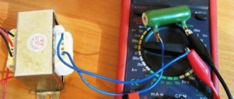
It is very useful for novice radio amateurs to be able to and know how to test a transformer with a multimeter. Such knowledge is useful because it saves time and money.
In most linear power supplies, the lion's share of the cost is the transformer. Therefore, if you happen to have a transformer with unknown parameters in your hands, do not rush to throw it away. Better pick up a multimeter.
Also, for some experiments we will need an incandescent lamp with a socket.
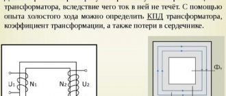
In order to more consciously carry out further experiments and experiments, you should understand how a transformer transformer is designed and works. Let's look at this in a simplified form here.
The simplest transformer consists of two windings wound on a core or magnetic circuit. Each winding consists of conductors isolated from each other.
And the core is made of thin sheets of special electrical steel, insulated from each other.
Voltage is applied to one of the windings, called the primary, and voltage is removed from the second, called the secondary.
When an alternating voltage is applied to the primary winding, since the electrical circuit is closed, a bullet is created in it for the flow of alternating electric current. An alternating magnetic field always forms around a conductor carrying alternating current.
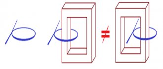
The magnetic field is closed and amplified by the magnetic core and induces an alternating electromotive force of EMF in the secondary winding.
i 2 flows in it .
This knowledge is not yet enough to fully understand how to test a transformer with a multimeter. Therefore, we will consider a number of useful points.
How to find out the power of a transformer
I have been repeatedly asked how to determine the power of a 50Hz transformer that does not have a marking, I will try to tell and show with a couple of examples. In general, there are quite a lot of ways to determine the power of a 50Hz transformer, I will list only a few of them.
1. Labeling.
Sometimes you can find a clear indication of power on the transformer, but this indication may not be noticeable at first glance. The option is, of course, very banal, but you should look for it first.
2. Overall power of the core.
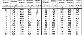
There are tables from which you can find the overall power of certain cores, but since the cores were produced in very different size configurations, and also differed in workmanship, the table may not always be correct. And it is not always possible to find them quickly. However, you can indirectly use tables from the descriptions of unified transformers.
3. Unified transformers.
Even during the union, and indeed after it, a huge number of unified transformers were produced, you can recognize them by the markings starting with TPP, TN, TA. If TA is less common, then TPP and TN are found very often.
Determination of interturn short circuit
Another common failure of transformers is interturn short circuit. It is almost impossible to check a pulse transformer for such a malfunction with just a multimeter. However, if you attract your sense of smell, attentiveness and sharp vision, the problem can well be solved.
A little theory. The wire on the transformer is insulated exclusively with its own varnish coating. If an insulation breakdown occurs, the resistance between adjacent turns remains, as a result of which the contact area heats up. That is why the first step is to carefully inspect the device for streaks, blackening, burnt paper, swelling and a burning smell.
Next, we try to determine the type of transformer. Once this is achieved, you can look at the resistance of its windings using specialized reference books. Next, switch the tester to megohmmeter mode and begin measuring the insulation resistance of the windings. In this case, the pulse transformer tester is a regular multimeter.
Each measurement should be compared with that indicated in the reference book. If there is a discrepancy of more than 50%, then the winding is faulty.
If the resistance of the windings is not indicated for one reason or another, the reference book must provide other data: the type and cross-section of the wire, as well as the number of turns. With their help, you can calculate the desired indicator yourself.
How to find out the power of a transformer?
Radio electronics for beginners
For the manufacture of transformer power supplies, a single-phase power transformer is required, which reduces the alternating voltage of the 220 volt mains to the required 12-30 volts, which is then rectified by a diode bridge and filtered by an electrolytic capacitor.
These transformations of electric current are necessary since any electronic equipment is assembled on transistors and microcircuits, which usually require a voltage of no more than 5-12 volts.
To assemble a power supply yourself, a novice radio amateur needs to find or purchase a suitable transformer for the future power supply. In exceptional cases, you can make a power transformer yourself. Such recommendations can be found on the pages of old books on radio electronics.
But nowadays it’s easier to find or buy a ready-made transformer and use it to make your own power supply.
Full calculation and independent production of a transformer for a beginning radio amateur is quite a difficult task. But there is another way. You can use a used but serviceable transformer. To power most home-made designs, a low-power power supply with a power of 7-15 watts is enough.
If the transformer is purchased in a store, then, as a rule, there are no special problems with selecting the right transformer. The new product has all its main parameters indicated, such as power , input voltage , output voltage , as well as the number of secondary windings, if there is more than one.
But what if you come across a transformer that has already worked in some device and you want to reuse it to design your own power supply? How to determine the power of a transformer, at least approximately? The power of the transformer is a very important parameter, since the reliability of the power supply or other device you assemble will directly depend on it. As you know, the power consumed by an electronic device depends on the current it consumes and the voltage required for its normal operation. Approximately this power can be determined by multiplying the current consumed by the device ( In) by the supply voltage of the device ( Un ). I think many are familiar with this formula from school.
P=Un * In
,where Un – voltage in volts; Iн – current in amperes; P – power in watts.
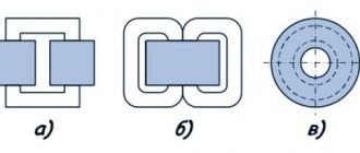
Let's look at determining the power of a transformer using a real example. We will train on the TP114-163M transformer. This is an armor-type transformer, which is assembled from stamped W-shaped and straight plates.
is worth noting that transformers of this type are not the best in terms of efficiency . But the good news is that such transformers are widespread, often used in electronics and can be easily found on the shelves of radio stores or in old and faulty radio equipment.
In addition, they are cheaper than toroidal (or, in other words, ring) transformers, which have high efficiency and are used in fairly powerful radio equipment.
So, before us is the transformer TP114-163M. Let's try to roughly determine its power. As a basis for calculations, we will take recommendations from the popular book by V.G. Borisov "Young Radio Amateur".
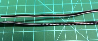
To determine the power of a transformer, it is necessary to calculate the cross-section of its magnetic core. In relation to the TP114-163M transformer, the magnetic core is a set of stamped W-shaped and straight plates made of electrical steel. So, to determine the cross-section, it is necessary to multiply the thickness of the set of plates (see photo) by the width of the central lobe of the W-shaped plate.
Check procedure
Testing a transformer begins with identifying the windings. This can be done using markings on the device. Pin numbers, as well as their type designations, should be indicated, which allows you to establish more information in reference books. In some cases there are even explanatory drawings. If the transformer is installed in some kind of electronic device, then the electronic circuit diagram of this device, as well as a detailed specification, can clarify the situation.
So, when all the conclusions are determined, it’s the tester’s turn. With its help, you can identify the two most common faults - a short circuit (to the housing or an adjacent winding) and a winding break. In the latter case, in ohmmeter mode (resistance measurement), all windings are called back one by one. If any of the measurements shows one, that is, infinite resistance, then there is a break.
There is an important nuance here. It is better to check on an analog device, since a digital one can give distorted readings due to high induction, which is especially typical for windings with a large number of turns.
No-load current measurement
When, as a result of testing, it turns out that the converter is in working condition, it is recommended to also check its no-load current. As a rule, if the device is working properly, then this parameter is within 10-15% of the nameplate value. The rated value should be considered the current under load.
Before checking the idle value, the multimeter is switched to the ammeter position. It should be taken into account that when electricity enters the winding, the inrush current significantly exceeds the rating value, so the tester is connected to the device being tested in a short-circuited manner.
Indirect method
This method includes several tests, each of which displays the state of the device in one aspect. Therefore, it is advisable to carry out all these tests together.
Determining the reliability of winding terminal markings
To carry out this test, the multimeter must be switched to ohmmeter mode. Next, you need to “ring” all available conclusions in pairs. Between those of them that belong to different coils, the resistance will be equal to infinity. If the multimeter shows a specific value, then the terminals belong to the same coil.
You can immediately compare the measured resistance with that given in the reference book. If there is a discrepancy of more than 50%, then an interturn short circuit or partial destruction of the wire has occurred.
Connecting a transformer to a multimeter
Please note that on coils with high inductance, that is, consisting of a significant number of turns, the digital multimeter may erroneously show an overestimated resistance. In such cases, it is advisable to use an analog device.
The windings should be checked with direct current, which the transformer cannot transform.
When using an alternating voltage, an emf will be induced in other coils and it is quite possible that it will be quite high. So, if an alternating voltage of only 20 V is applied to the secondary coil of a 220/12 V step-down transformer, then a voltage of 367 V will appear at the primary terminals and if they are accidentally touched, the user will receive a strong electric shock.
Next, you need to determine which terminals should be connected to the current source and which to the load. If it is known that the transformer is a step-down transformer, then the coil with the largest number of turns and the highest resistance must be connected to the current source. With a step-up transformer the opposite is true.
All methods for measuring electric current
But there are models that have both step-down and step-up coils among the secondary coils. Then the primary coil can, with a certain degree of probability, be recognized by the following characteristics: its terminals are usually attached away from the rest, and the coil can also be located on the frame in a separate section.
The development of the Internet has made this method possible: you need to take a photo of the transformer and write a request with the attached photo and all available information (brand, etc.) to one of the online thematic forums.
Perhaps one of its participants has dealt with such devices and can tell you in detail how it needs to be connected.
If the secondary coil has intermediate taps, it is necessary to recognize its beginning and end. To do this, you need to determine the polarity of the terminals.
Determining the polarity of winding terminals
As a meter, you should use a magnetoelectric ammeter or voltmeter, the polarity of the terminals of which is known. The device must be connected to a secondary coil. It is most convenient to use those models in which the “zero” is located in the middle of the scale, but in the absence of one, the classic one with the “zero” location on the left will do.
If there are several secondary coils, the others need to be bypassed.
Checking the polarity of phase windings of AC electrical machines
A small direct current must be passed through the primary coil. A regular battery can serve as a source, but a resistor must be included in the circuit between it and the coil to prevent a short circuit. An incandescent lamp can serve as such a resistor.
There is no need to install a switch in the primary coil circuit: just follow the multimeter needle to close the circuit by touching the wire from the lamp to the coil output, and immediately open it.
If the same poles from the battery and the multimeter are connected to the terminals of the coils, that is, the polarity is the same, then the arrow on the device will move to the right.
For a multi-polar connection - to the left.
When the power is turned off, the opposite picture will be observed: with a unipolar connection, the arrow will move to the left, with a multi-polar connection - to the right.
On a device with a “zero” at the beginning of the scale, the movement of the needle to the left is more difficult to notice, since it almost immediately bounces off the limiter. Therefore you need to watch carefully.
Using the same scheme, the polarities of all other coils are checked.
A multimeter is a very necessary device for measuring current strength, which is used to identify malfunctions of certain devices. – read useful tips on choosing.
Instructions for checking diodes with a multimeter are presented.
Removing the magnetization characteristic
To be able to use this method, you need to prepare ahead of time: while the transformer is new and known to be in good working order, its so-called current-voltage characteristic (volt-ampere characteristic) is measured. This is a graph showing the dependence of the voltage at the terminals of the secondary coils on the magnitude of the magnetizing current flowing through them.
Schemes for measuring magnetization characteristics
Having opened the circuit of the primary coil (so that the results are not distorted by interference from nearby power equipment), alternating current of varying strength is passed through the secondary, measuring the voltage at its input each time.
The power of the power supply used for this must be sufficient to saturate the magnetic circuit, which is accompanied by a decrease in the slope of the saturation curve to zero (horizontal position).
Measuring instruments must belong to an electrodynamic or electromagnetic system.
Before and after the test, the magnetic circuit must be demagnetized by increasing the current in the winding in several steps and then reducing it to zero.
As you use the device, you need to take the current-voltage characteristic at certain intervals and compare it with the original one. A decrease in its steepness will indicate the appearance of an interturn short circuit.
Checking household step-down devices
It is worth noting the moment of checking classic step-down transformers with a multimeter tester. They can be found in almost all power supplies that reduce the input voltage from 220 Volts to the output voltage of 5-30 Volts.
The first step is to check the primary winding, which is supplied with a voltage of 220 Volts. Signs of a primary winding malfunction:
- the slightest visibility of smoke;
- the smell of burning;
- crack.
In this case, the experiment should be stopped immediately.
If everything is normal, you can proceed to measurements on the secondary windings. You can touch them only with the tester contacts (probes). If the results obtained are less than the control ones by at least 20%, then the winding is faulty.
Unfortunately, such a current block can be tested only in cases where there is a completely similar and guaranteed working block, since it is from it that the control data will be collected. It should also be remembered that when working with indicators of the order of 10 ohms, some testers may distort the results.
Types of transformer windings
Depending on the relative position of the current-conducting elements, the direction of their winding and the shape of the wire section, several types of transformer windings are distinguished:
- Single or double layer cylindrical winding made of rectangular wire. The technology of its manufacture is very simple, thanks to which such coils have become widespread. The winding is thin, which reduces heating of the device. Among the disadvantages, the low strength of the structure should be highlighted.
- Multilayer cylindrical winding is similar to the previous type, but the wire is arranged in several layers. In this case, the windows of the magnetic system are filled better, but the problem of overheating appears.
- A cylindrical multilayer winding made of round wire has properties close to previous types of windings, but the disadvantages include a loss of strength as power increases.
- Helical winding with one, two or more strokes has high strength, excellent insulation and cooling. Compared to cylindrical windings, screw windings are more expensive to produce.
- The continuous winding of rectangular wire does not overheat and has a significant margin of safety.
- The multilayer foil winding is resistant to damage and fills the window of the magnetic system well, but the production technology of such coils is complex and expensive.
Transformers have six basic winding types.
On transformer diagrams, the beginning of the high voltage windings is indicated in capital letters of the Latin alphabet (A, B, C), and the same part of the low voltage wires is indicated in lowercase letters. The opposite end of the winding has a generally accepted symbol, consisting of the final three letters of the Latin alphabet - X, Y, Z for incoming voltage and x, y, z for outgoing.
Windings are distinguished by purpose:
- main ones - these include the primary and secondary windings, through which current is supplied from the network and supplied to the point of consumption;
- regulating - are taps, the main function of which is to change the voltage transformation ratio;
- auxiliary - used to meet the needs of the transformer itself.