NTMI type transformer is equipment capable of converting and measuring alternating electric current on a large scale for the operation of protection, alarms and other similar equipment. The unit allows you to monitor the condition of the insulating layers in the network. To choose the right instrument transformers, it is necessary to consider the technical characteristics and commissioning features.
Device
Transformer type NTMI 6 (10) kV is applicable for changing voltage levels and metering electricity in the network. Used in systems with isolated class neutral. Users ask when purchasing whether grounding is required for the presented structures. The device passport gives a clear answer. Neutral and grounding are required in automatic networks. The transformer connection diagram and unit maintenance are presented by the manufacturer in the instructions.
The transformer container is a metal structure. The lid is equipped with hooks that allow you to transport and install the device in a designated area. The structure has an oil plug at the bottom. The ground bolt is installed here. At the top of the unit there are HV and LV outputs. The hole for topping up the oil cooler is located here and is closed with a plug.
The transformer of category NTMI 10 (6) kV is equipped with a steel core. The coil circuit is copper.
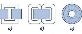
STMI design
The NTMI transformer tank is welded, round in shape. The assembly is lifted using brackets located on the transformer cover. At the bottom there is a plug for draining the oil, a plug for filling oil and taking an oil sample, and a grounding bolt. On the tank cover there are high voltage (HV), low voltage (LV) inputs, and a plug for adding oil. To ensure tightness, oil-resistant rubber is used. Transformers NTMI-6, NTMI-10 are filled with transformer oil having a breakdown voltage of at least 40 kV.
The active part consists of a magnetic core made of cold-rolled electrical steel, windings, HV and LV taps. The windings of transformers NTMI-6, NTMI-10 are made of copper wires. HV and LV bushings for outdoor installation, removable, porcelain feed-through insulators.
The assembly of NTM transformers is carried out carefully and accurately in accordance with the design documentation. The windings are installed and secured to the corresponding magnetic cores, after which the yoke is installed, electrical connections and drying under vacuum are carried out. Before installing the active part in the NTMI transformer tank, the connection of the windings, the transformation ratio and the angular error of the phase vector shift are checked.
After thorough drying and checking the tightening torques of the bolted connections, the active part is installed in the transformer tank, the transformer cover is attached and filled with oil.
Diagram and dimensions of the transformer NTMI-6-66
Overall dimensions of NTMI-6
Tests
All NTM transformers are subject to standard and acceptance tests in accordance with GOST 11677 and regulatory documentation.
Users sometimes ask when purchasing whether grounding is required for the presented structures. The device data sheet gives a clear answer. In automatic networks, neutral and grounding are required. The connection diagram for the STMI transformer and maintenance of the unit are presented by the manufacturer in the instructions.
Design and connection of voltage transformer NTMI-6
Transformers NTMI 10
Transformers NTMI-6, NTMI-10
Assembly and commissioning
The voltage transformer of the NTMI 10 (6) kV group has different dimensions and weight (according to the power). The cost also differs according to the specified characteristics. Assembly is carried out according to the manufacturer's instructions. The windings must be fixed to the rods of the magnetic drive, and a yoke is mounted. Electrical switching is carried out in accordance with existing standards. The drying procedure is in progress.
The active part is installed in the tank. The quality of the connection of the windings is controlled while the unit is not under voltage. The transformation coefficient and the error in the angular shift of the phase vectors are estimated. A voltage transformer of category NTMI 6 (10) kV must be thoroughly dried. Connections are checked. The lid is placed in the designated place and oil is poured into the tank.
The coolant level is monitored. The quality of the oil meets the requirements of the standards. Additional accessories are installed.
Transformers NTMI-6, NTMI-10
Three-phase oil voltage transformers of the NTMI series type are designed for large-scale conversion of alternating current electrical voltage for the purpose of further measurement and supply to protection and signaling devices in automation circuits with an isolated neutral.
They are used to reduce voltage from 6 or 10 kV to 100 V, as well as for metering, including commercial. NTMI transformer tanks are welded. To transport the transformer there are brackets located on the transformer cover. At the bottom there is a plug for draining the oil, a plug for filling and checking the oil, and a grounding bolt. High voltage (HV) and low voltage (LV) inputs are located on the tank cover, and there is also a plug for adding oil.
The transformer magnetic core is made of cold-rolled electrical steel. Transformer windings made of copper wires. HV and LV bushings for outdoor installation, removable, porcelain feed-through insulators.
The final assembly is carried out strictly according to the design documentation. The windings are placed and fixed on the corresponding magnetic cores. Next, the yoke is installed, the necessary electrical connections are made and drying is carried out. Before installing the active part in the transformer tank, it is necessary to check the connection of the windings, the transformation ratio and the angular error of the phase vector shift.
After thorough drying and checking the tightening torques of the bolted connections, the active part is installed in the transformer tank, the transformer cover is attached and filled with oil. At the final installation stage, the transformer is equipped with the ordered accessories.
Decoding the transformer markings.
Decoding STMI
NTMI - 10(6)-U3(T3) NT - three-phase voltage transformer M - oil cooling with natural circulation of air and oil I - measuring 10(6) - rated voltage of the HV winding, kV U3(T3) - climatic version and placement category according to GOST 15150
Technical characteristics of STMI
| Transformer | Rated voltage of windings, kV | Rated voltage, kA in accuracy class | Maximum power limit | N, mm | Weight, kg | ||||
| VN | NN (main) | NN (additional) | 0,5 | 1,0 | 3,0 | ||||
| STMI-6 | 6 | 0.1 | 0.1/3 | 75 | 150 | 300 | 630 | 400 | 67 |
| NTMI-10 | 10 | 0.1 | 0.1/3 | 150 | 300 | 500 | 1000 | 490 | 87 |
Current frequency: 50Hz. Number of phases: 3. Connection diagram and group: Y/Yn-0.
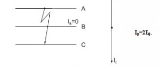
Electrical diagram of the transformer NTMI-6, NTMI-10
Overall dimensions of transformer NTMI-6, NTMI-10
I - winding diagram; a - primary; b - secondary; c - additional; II - overall and installation dimensions; 1 - oil drain plug; 2 — grounding bolt. Characteristics of transformer OSM1
Designation
Units of the presented type are designated according to the installed system. Marking allows you to identify the features of the equipment. Operating personnel must see a sign indicating the type of equipment. The decoding of the data is as follows: NTMI-6(10) – UZ (TZ).
- N - voltage transformer.
- T - three-phase.
- M – oil type system cooler, natural circulation.
- And - measuring, an additional winding of the KIZ type is provided.
- 6(10) – parameters of the HV terminal winding, kV.
- UZ (TZ) is a type of climatic placement.
The information is printed on a special plate, which is attached with screws to the transformer housing. The marking must be placed in a visible place.
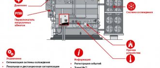
Features of operation
Installations of the presented category are operated strictly in accordance with generally recognized standards. Commissioning and monitoring of equipment condition is carried out by trained, experienced employees.
The presented equipment is installed in areas with moderate and cold climates. It is prohibited to store fire hazardous, explosive, chemical substances, gases, or liquids nearby.
The unit is installed at an altitude of no more than 1 km above sea level. The design is not designed to withstand vibration, mechanical shock or shaking. The work cycle is quite long. The equipment is turned off for scheduled repairs and maintenance. If signs of malfunction appear, in an emergency situation, the power is immediately turned off.
The ambient temperature can reach from +40 to -45ºС for category U1. Climatic modification HL1 allows operation in the range from +40 to -60ºС. Relative humidity is 80%. The above conditions contribute to long-term, efficient operation of the equipment.
Having considered the features, operating principles and designations of STMI transformers, you can choose the right device that meets the needs of consumers.
NTMI-10-10000/100V U3 voltage transformer
The three-phase oil voltage transformer NTMI-10 is used to reduce high voltage 10 kV to 100 V, as well as for metering, including commercial and protective devices of electrical energy in AC installations.
Technical characteristics of NTMI-10.
| Transformer | Rated voltage of windings, kV | Rated voltage, kA in accuracy class | Maximum maximum power, VA | Weight, kg | ||||
| VN | NN (main) | NN (additional) | 0,5 | 1,0 | 3,0 | |||
| NTMI-10 | 10 | 0.1 | 0.1/3 | 150 | 300 | 500 | 1000 | 87 |
Note: At the customer's request, it is possible to manufacture NTMI transformers of other voltage combinations.
NTMI-10 transformers comply with the requirements of TU 659 RK 0001 0033-22 and GOST 1983-2001.
Transformers are supplied with initial verification. Interverification interval is 8 years.
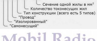
Structure of the symbol for voltage transformers N T M I - X X X N Voltages T Three-phase M Oil I With additional winding for insulation control -10 Voltage class of the primary winding, kV X Climatic version (U UHL) X Placement category (3) according to GOST 15150 An example of a transformer symbol: Transformer with a primary winding voltage of 10 kV, climatic version U, placement category 3 when ordering and in the documentation of another product: “Transformer NTMI-10 U3 ST AO 00010033-019-2009”
Operating conditions for NTMI-10 transformers.
Transformers NTMI-10 are intended for operation in areas with temperate and cold climates, with:
- non-explosive and chemically active environment
- installation altitude above sea level no more than 1000 m.
- NTMI-10 transformers are not designed to operate under conditions of: shaking, vibration, shock.
- long operating mode.
- Ambient temperature: -45C to +40C for U1.
- Ambient temperature: -60C to +40C for HL1.
- relative air humidity no more than 80% at 25C.
Design of transformers NTMI-10.
Transformer tanks are welded. The NTMI10 transformer assembly is lifted using brackets located on the transformer cover. At the bottom there is a plug for draining the oil, a plug for filling oil and taking an oil sample, and a grounding bolt. On the tank cover there are HV, LV inputs, and a plug for adding oil. The active part consists of a magnetic core made of cold-rolled electrical steel, windings, HV and LV taps. Transformer windings made of copper wires. HV and LV bushings for outdoor installation, removable, porcelain feed-through insulators.
Assembly. The final assembly is carried out carefully and accurately according to the design documentation. The windings are installed and secured to the corresponding magnetic cores, after which the yoke is installed, electrical connections and drying under vacuum are carried out. Before installing the active part in the transformer tank, the connection of the windings, the transformation ratio and the angular error of the phase vector shift are checked. After thorough drying and checking the tightening torques of the bolted connections, the active part is installed in the transformer tank, the transformer cover is attached and filled with oil. At the final installation stage, the transformer is equipped with the ordered accessories.
Tests . All NTMI-10 transformers are subject to type and acceptance tests in accordance with GOST 11677 and regulatory documentation.
Manufacturer's Warranties:
The warranty period for the operation of the NTMI-10 voltage transformer is 3 (three) years from the date of its commissioning, but not more than 3.5 years from the date of release. The manufacturer guarantees that the transformer meets the requirements of the standards provided that the consumer complies with the operating conditions, transportation, storage and installation.
Standard delivery set:
- Voltage transformer type NTMI 10
- Technical description and operating instructions
- Passport.
Attention: product characteristics, delivery package and appearance may be changed by the manufacturer without prior notice!