Before you figure out how to connect a current transformer, you need to understand what a transformer is and why it is needed. A transformer is an electromagnetic device that is designed to convert voltage values. Moreover, its operation is possible only with alternating voltage or, in extreme cases, with pulsating voltage. If a pure direct voltage is connected to any transformer, then at its output the potential between the terminals will be zero. Every transformer consists of a primary winding and one or more secondary windings, depending on its purpose and design.
Purpose and design features
In turn, a current transformer is a device that operates on the principle of electromagnetic induction and serves to measure current in high-voltage circuits, as well as to organize protection systems for electrical equipment.
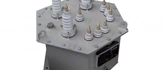
That is, in order to measure current in circuits with dangerously high voltages, for example, 6 kV, you cannot simply take a measurement with an ammeter; this is very dangerous both for personnel and for the device itself. Therefore, the main task of current transformers is to separate high-voltage current-carrying parts and convert energy that is safe for both personnel and equipment. Current transformers (CTs) are widely used in relay protection at substations and switchgears. Therefore, high demands are placed on their accuracy and connection. Often, its primary winding is any conductive busbar or cable core; the secondary winding is single or group, with several terminals for protection, control and measurement circuits. Also, metering elements - electricity meters - are connected through current transformers. That is, according to their purpose, current transformers can be divided into four main groups:
- measuring;
- protective;
- intermediate;
- laboratory
One type of portable device is a clamp meter. They can very easily measure currents in circuits up to 1 kV. True, their measurement range for current is very small; it will be problematic for them to measure loads of 1000 Amps.
Connection of current transformers and relay windings in a partial star
Symmetrical load with three-phase short circuit.
Two-phase short circuit
Two-phase short circuit AB or BC For different types of short circuit, the current in the relay and its sensitivity will be different. The current in the relay will be zero during a single-phase short circuit of phase B. This circuit can be used when transformer action is not required to protect against various phase-to-phase short circuits with the connection of windings Y/* - group 11, and when this protection provides the necessary sensitivity.
How to install a current transformer
How it works and how to choose a current transformer
According to the type and method of installation, they are divided into:
- Passage;
- Support;
- Built into electrical equipment;
- For electrical installations up to 1 kV or higher;
- For outdoor installation in outdoor switchgear (open switchgear);
- For indoor installation in closed switchgear (closed switchgear).
Often, in circuits with low-power motors and transformers designed for 1 kV and below, the installation of a current transformer is not required. These are all kinds of step-down lighting transformers, compressors, fans, heating systems. In general, current transformers are installed extremely rarely in everyday life, except on transformers that supply entire areas or groups of houses.
Current transformer connection
Let's consider several options for connecting current transformers in a three-phase voltage circuit.
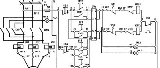
This circuit, where three current transformers are connected in a star, is widely used to protect circuits from single-phase and multi-phase short circuits. If a current flows in the circuits below that for which relays KA1-KA3 are configured, then this is called normal operating mode and none of the protections will operate. The current that flows through the K0 relay is calculated as the geometric sum of the currents of all three phases. When the current increases in one of the phases, the current will increase and one or more relays KA1-KA3 will operate in the protective transformer circuit, depending on the location of the current increase. This does not necessarily happen during a short circuit; even if the load on the controlled equipment is higher than the rated load, it will cause a shutdown. Thereby saving expensive electrical equipment from abnormal operation. If there is a ground fault, current will also appear in the K0 relay circuit, thereby turning off the electrical installation.
A circuit with transformers is used to protect against phase-to-phase faults to organize circuits with a grounded neutral. A partial star circuit is most often used for low-power sources and consumers, when there are additional types of various protections.
This type of connection into a triangle on one side and a star on the other is used in electrical installations for differential protection.
Connecting current transformers, thus, makes it possible to protect against phase-to-phase faults and overcurrent in each phase, but there is no shutdown in the event of a short circuit to ground. Therefore, it is connected this way in exceptional, very rare cases.
Connection diagrams for CT windings
There are the following basic circuits for connecting the secondary windings of a current transformer when powering protective relay devices:
- Full star diagram. In this case, current transformers are switched in all power phase lines. Their secondary windings are connected by a star circuit to the relay windings. All CT terminals of the same value must converge to the zero point. According to this scheme, its own relay will respond to a short circuit (short circuit) of any phase. If a short circuit occurs on the ground bus, then a relay will operate in the star (in the zero wire).
- Connection diagram of transformer windings in a partial star. This option involves installing CTs not on all phases, but only on two. The secondary windings are also connected to the relay with a star. This circuit is effective only when there is a short circuit between phases. In case of a phase short circuit to zero (where the CT was not installed), the protection system will not work.
- The triangle circuit is on transformers, the star is on relays. Here the CTs with their opposite terminals of the secondary windings are connected in series with a triangle. The vertices of this triangle go to the rays of the star, where the relay is installed. The circuit is used for such types of protection as distance and differential.
- CT connection diagram based on the two-phase difference principle. The circuit reacts only to phase-to-phase short circuits with the required sensitivity.
- Zero-sequence current filtering circuit.
Current transformer installation
Current transformer - operating principle, purpose and device
Before installing the current transformer itself, it is necessary to inspect it and check the insulation resistance. If it is low, that is, less than 1 kOhm per 1 Volt, then first dry it thoroughly using a fan heater or other heat gun. The insulation resistance should be checked every half hour. During the audit, they also check the completeness of the device, fastening elements, the condition of the porcelain dielectric parts and the housing. Need to inspect:
- secondary terminal block for protection and control circuits;
- presence of their designations, markings;
- passport table;
- condition of the threads on the bolted connections of the terminals;
- presence of nuts and washers.
Before you begin directly installing the current transformer, of course, everything starts with turning off the high-voltage installation, checking that there is no voltage on live parts, and also installing portable grounding connections. All this is the main safety measure for installation personnel. Then markings are made at the installation site, and if necessary, drilling work is carried out in the places where the structure is attached. If the room is damp, then it is worth taking measures to prevent the formation of corrosion (installing dryers and painting contact connections). It is prohibited to install the transformer and install it in such a way that their housings are close to each other. The distance must be at least 100 mm.
It is advisable, if possible, that the markings should be visible from behind the fences.
The main rule for connecting any current transformer is to prohibit its inclusion in a circuit without a load on the secondary winding. If it is not possible to connect the device, then they must be connected to each other so that high voltage does not arise on it, which almost always leads to failure of the measuring device.
Operating principle of instrument transformers
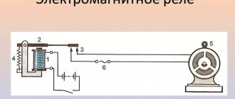
The internal structure and method of operation of current transformers is based on simple principles, the circuit is simple. The primary winding of the coil is connected in series to allow the phase load current to flow. Afterwards, the induction of an electromagnetic field occurs, which passes to the winding of the secondary coil. Three-phase transformers are inserted into the latter.
To reduce this, the transformation ratio is used, due to which less electricity is supplied to the secondary winding. This ensures normal operation of the meter, and the output readings must be multiplied by the coefficient number to obtain the true value of the consumed voltage.
Thus, the transformer mechanism converts the high voltage at the input into an acceptable voltage for the meter. The equipment operates at a frequency of 50Hz and a current of 5A. for example, if a device has a load limit of 100A, the output data is multiplied by 20 (100 divided by 5).
Thanks to the adapters, meters are protected from voltage surges, short circuits, and overloads. Moreover, if a transformer burns out, it is easier to replace than an electrical meter.
When connecting, it is worth considering some disadvantages. The most common option is that the starting value of the meter current is not taken into account. In this case, the counter simply will not be able to start working.
Failure to observe polarity when connecting is another common mistake. At the input of the primary winding coil there are two terminals - one for phase L1, the other for load L2. The measuring winding for the coil is also equipped with two terminals (I1 and I2). The cable must be connected to the appropriate contacts, having previously calculated the maximum load.
If you connect the microcontacts and wires incorrectly, a short circuit will occur. This can lead to device failure and fire.
Installation of power transformers
The installation of a power transformer must be carried out by specially trained teams under the guidance of highly qualified electrical personnel. They must have sufficient experience in performing these works in strict accordance with TTM 16.800.723–80. Oil transformers used in power electrical installations can be sent to the manufacturer in the following states:
- Fully filled with oil and assembled;
- Partially disassembled, with a sealed tank in which oil is filled below the cap;
- Partially dismantled without oil, the tank is filled with inert gas;
All work on the installation of transformers is carried out in a clear, regulated sequence
- Unloading electrical equipment after arrival from the manufacturer's factory;
- Transportation to the installation site;
- Preparatory installation work;
- Checking the condition of all windings and switches;
- Installation on a pre-made strong foundation;
- Installation of the cooling system and oil filling, connection of blower fans;
- Inspection for oil leaks;
- Testing of the transformer and trial switching is performed immediately without load during the day.
At the same time, it is better and safer to install transformers during daylight hours.
Parallel connection of transformers
Their parallel operation is necessary to provide more power to the consumers they supply with energy. To organize and include power transformers in parallel, it is necessary to take into account five basic rules and conditions:
- The winding connection groups are the same;
- The transformation ratios of all converters connected in parallel are the same. The difference is allowed within ±0.5%;
- Correct phasing has been performed;
- The short circuit voltage of all transformers must be equal or differ by no more than 10%;
- The power ratio should differ by no more than three times.
Before connecting the transformer to such parallel operation, you must ensure that all these points are met.
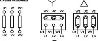
Connection diagrams for power transformer windings
For three-phase networks, there are three main circuits for connecting the windings of power transformers. Each of the methods of such connection has its own influence on the operating mode of the transformer.
A star connection is when there is a common point of union of the beginnings or ends of all windings (zero point). The following pattern is present here:
- Phase and line currents have the same magnitude.
- The phase voltage (between phase and neutral) is less than the linear voltage (between phases) by the root of 3.
With regard to the windings of high voltage (HV), medium voltage (MV) and low voltage (LV) the following schemes are more often used:
- They connect the HV windings with a star, bringing the wire out from the zero point for increasing and decreasing T of any power.
- The MV windings are connected in the same way.
- LV windings are rarely connected with a star in step-down transformers, but when this happens, the neutral wire is brought out.
A delta connection involves connecting a transformer in series in a circuit where the beginning of one winding has contact with the end of another, the beginning of another with the end of the last, and the beginning of the last with the end of the first. Electricity outlets emerge from the vertices of the triangle. In this connection diagram of the windings of a three-phase transformer there is a pattern:
- Phase and line voltages have the same magnitude.
- Phase currents are less than linear currents by the root of 3.
As a rule, the LV windings of any step-down and step-up three-phase T are connected into a triangle into two or three windings, as well as powerful single-phase ones assembled in groups. For HV and MV, a delta connection is usually not used.
A zigzag-star connection is characterized by equalizing the magnetic flux across the phases of the transformer if the load on them in the secondary windings is unevenly distributed.
If the transformer is connected in reverse
A transformer is a unique device that can work in one direction or the other. That is, just as a step-up transformer can become a step-down transformer, and vice versa. For example, if it is designed to connect a voltage of 6 kV to its primary winding, and 0.4 kV should appear on the secondary winding, then it can also work in the other direction. If 0.4 kV is applied to the secondary winding, then 6 kV will appear on the primary winding. This feature can be very dangerous when carrying out preventive and routine repairs of this equipment. Be sure to turn them off on both the low and high sides. You need to remember this rule when preparing jobs.
Schemes and groups of connections of transformer windings
In addition to connection diagrams, there are groups that mean nothing more than a displacement of the vector directions of the linear EMF of the primary windings relative to the electromotive force in the secondary windings. These angular differences can vary within 360 degrees. Factors defining the group are:
- Direction of winding turns.
- Method of placement on the coil core.
For convenience, the designation of groups adopted an hourly angular reading, divided by 30 degrees. Therefore, there were 12 groups (from 0 to 11). With all basic connections of transformer windings, all displacements are possible at an angle that is a multiple of 30 degrees.
How to connect a step-down transformer
Most often, the installation of a transformer is required to reduce the voltage. Therefore, how to properly connect a transformer for such a step-down purpose is a question that comes up very often. When connecting this device, the main thing is to choose it correctly in accordance with:
- The magnitude of the input voltage, that is, supplied to the primary;
- The magnitude of the output voltage at the terminals, there can be several of them, depending on the design;
- Power, which depends on the power of consumers.
Connecting a diode bridge to a transformer can be done if there is a need to obtain a constant voltage. Here are diagrams for connecting a diode bridge to a single-phase or three-phase network.
Balancing transformer
If the step-down transformer is loaded unevenly, phase imbalance will occur, which is a negatively influencing mechanism. The consequence of such operation and consumption of electrical receivers will be an increase in electricity consumption, and over time, failures and premature destruction of insulation. The safety of eating consumers will be at risk. In order to prevent this, it is necessary to balance the phases through the use of balun transformers.
As can be seen from the diagram, there is an additional winding that must withstand the rated current of one of the phases. It is connected to the break of the neutral conductor, which leads to good results, that is, the symmetrical generation of equal currents in the load.
Coffee capsule Nescafe Dolce Gusto Cappuccino, 3 packs of 16 capsules
1305 ₽ More details
Coffee capsules Nescafe Dolce Gusto Cappuccino, 8 servings (16 capsules)
435 ₽ More details
Samsung Galaxy S20 smartphones
What is the third harmonic used for?
In electrical engineering there is the concept of magnetizing current. It is this that generates the electromotive force (EMF). The shape of such a current is not sinusoidal, since higher harmonic components are present here. The third harmonic is responsible for transmitting the phase voltage curve without distortion (a distorted shape is undesirable for the operation of the equipment).
To obtain the third harmonic, a prerequisite is a delta connection of at least one winding. If the connection diagram of the star-star transformer windings is taken as the basic one, for example, in transformers with two windings, it is impossible to obtain the third harmonic without additional technical intervention. Then a third winding is wound onto the transformer, which is connected in a triangle, sometimes without leads.