Joule-Lenz law
Note 1
James Joule was the first to formulate the dependence of heat release on the strength of electric current, which happened in 1841. Later this was done by Emil Lenz. This is how the Joule-Lenz law appears, which makes it possible to calculate the power of electric heaters along with heat losses in power lines.
Are you an expert in this subject area? We invite you to become the author of the Directory Working Conditions
In verbal formulation, according to the research of these scientists, the law will sound like this: the amount of heat released in a certain volume of a conductor at the moment of flow of electric current turns out to be directly proportional to the product of the magnitude of the electric field strength and the density of the electric current. The formula is written like this:
$w=\vec{j}\vec{E} = QE^2$, where:
- $w$ represents the power of heat generated per unit volume;
- $\vec{j}$ is considered to be the electric current density;
- $\vec{E}$ is the electric field strength;
- $Q$ is the conductivity of the medium.
Taking into account the constant current strength and resistance of the conductor over time, we can write the Joule-Lenz law in a more simplified way:
$Q = I^2Rt$
Applying Ohm's law in conjunction with algebraic transformations, we obtain the following equivalent formulas:
$Q = \frac{U^2t}{R} = UIt$
The research of physicists Joule and Lenz regarding heat release from the action of electric current has significantly advanced the scientific understanding of certain physical processes, and the basic formulas derived, without undergoing changes, continue to be actively used in various scientific and technical fields.
Finished works on a similar topic
Course work Heat and energy in an electrical circuit 490 ₽ Abstract Heat and energy in an electrical circuit 280 ₽ Test work Heat and energy in an electrical circuit 200 ₽
Receive completed work or specialist advice on your educational project Find out the cost
In the field of electrical engineering, there are several technical problems where the amount of heat that will be released during the flow of current is critically important when calculating parameters such as:
- heat loss in power lines;
- characteristics for wires of electrical wiring networks;
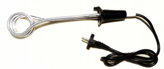
- thermal power of electric heaters;
- operating temperature of circuit breakers;
- melting temperature of fuses;
- heat generation of various electrical devices, as well as radio engineering elements.
Note 2
The thermal effect of electric current in power transmission line wires is undesirable due to significant losses of electricity due to heat generation. According to various data, up to 40% of all electrical energy produced globally is lost in power lines. In order to reduce losses in the process of transmitting electricity over long distances, the voltage in power lines is raised (with calculations made based on derivative formulas of the Joule-Lenz law).
Electrical energy and power
Nbsp; Questions for testing. 1. Electric circuit. Definition. Basic elements of an electrical circuit. Types of energy. Basic graphic symbols of elements and conductors. 2. Classification of electrical circuits. 3. Basic phenomena in an electrical circuit and quantities that characterize them (Physical processes in an electrical circuit. Electromotive force. Electric current, Voltage, Potential and potential difference, resistance, conductivity.) 4. Ohm’s law. Internal source resistance. Generalizing Ohm's law. 5. Kirchhoff's law. 6. Energy and power in an electrical circuit. 7. Sources of electrical energy. 8. Potential distribution along an unbranched electrical circuit. 9. Sources of electrical energy. 10. Circuit conversion method. Application of the method. Conversion of series-connected resistors or resistive elements. 11. Conversion of parallel connected resistors or resistive elements. 12. Method of direct application of Kirchhoff's laws (Kirchhoff's Laws, Calculation Procedure). 13. Method of nodal potentials. 14. Principle and method of application. 15. Equivalent generator method. 1. An electrical circuit is a set of electrical devices, objects (sources, receivers of electricity, switching, protective devices, etc.) and the conductors connecting them, which represent a path for the passage of electric current. The processes of transmission, distribution or conversion of electricity occurring in electrical circuits (hereinafter - EC) can be described using the concepts of EMF, voltage and current. The flow of electric current is possible only in a closed EC; When it opens at any point, the current flow will stop. Active and passive elements of an electrical circuit The elements that make up electrical circuits can be active and passive. The main feature of active components is their ability to release electricity. Typical representatives are generators and other sources of electricity, electrical signal amplifiers and others. Passive elements are considered to be various types of consumers and storage devices of electrical energy. These include capacitors, resistors, inductors and other two-terminal devices. There is multi-pole equipment that operates on the basis of two-pole elements. All active elements of an electrical circuit can be independent or dependent. The first category includes voltage and current sources. In turn, the voltage source is considered an idealized circuit element, in which the voltage at the terminals does not depend on the electric current flowing through it, and the internal resistance has a zero value. The current source is also an impeccable element in which the current does not depend on the voltage at the terminals, and the value of the internal resistance tends to infinity. Dependent sources of voltage and current are called such when these quantities depend on the voltage and current parameters in another section of the circuit. Typical representatives are electric lamps, transistors, and amplifiers operating in linear mode. The main passive elements of the electrical circuit are represented by resistors, inductive coils and capacitors, with the help of which the current and voltage parameters in individual sections are regulated. Resistance refers to idealized circuit elements. Its main property is irreversible energy dissipation. The relationship between voltage and current of resistive resistance is expressed by the formulas: u = iR, i = Gu, in which R is the resistance, measured in Ohms, and G is the conductivity, measured in Siemens. The relationship between these quantities is expressed by the formula R = 1/G. Idealized inductive circuit elements are capable of storing magnetic field energy. The main parameter is considered to be linear inductance, which is in a linear relationship between magnetic flux and current, graphically representing the Weber-ampere line. Inductance is also a proportionality coefficient measured in Henry. Capacitive elements - capacitors have the property of accumulating the energy of an electric field. The linear capacitance indicator is a linear relationship between charge and voltage, expressed by the formula q = Cu. Symbols of electrical circuit elements For the convenience of analysis and calculations of electrical circuits, all their components are displayed in the form of special diagrams. These diagrams consist of symbols of the elements used and methods of connecting them. Symbols in the CIS countries may differ from the symbols adopted in other countries; accordingly, the schemes themselves will differ, since different systems of graphic markings were used. All elements in the diagrams are conventionally divided into three groups: The first includes power sources that convert other types of energy into electrical energy. In this case they are considered primary. Secondary sources include, for example, rectifiers, which have electrical energy at the input and output. The second group is represented by energy consumers who convert electric current into heat, lighting, movement, etc. The third group includes control elements, without which the operation of any circuit is impossible. This includes connecting wires, switching equipment, measuring instruments and other devices for similar purposes. All these components are covered by a single electromagnetic process, so they are included in the overall scheme using special symbols. Please note that auxiliary elements may not be indicated on the diagrams. Connecting wires are also not indicated if their resistance is significantly lower than that of the component elements. Power supplies are designated in terms of electromotive force. Explanatory notes are provided if necessary. 2. Classification of electrical circuits By type of complexity: simple (unbranched), complex (branched); By type of current: alternating and direct current; By the composition of elements: active, passive, linear, nonlinear circuits; By the nature of the distribution of parameters: circuits with concentrated and distributed parameters; AC circuits are divided by the number of phases: single-phase, multiphase. Electrical circuits are calculated. To facilitate calculations, an equivalent circuit of the electrical circuit is drawn up, i.e. diagram showing the properties of a circuit under certain conditions. The equivalent circuit shows all the elements whose influence on the calculation result cannot be neglected, and indicates all the electrical connections between them. Any electrical circuit can be represented in the form of a diagram using conventional graphic symbols. Symbols are established by the standards of the ESKD system. Electric circuits can have a series or parallel connection of electrical elements. Any element has an input (beginning) or an output (end). When connecting elements in series, the output of the previous element is always connected to the input of the subsequent element. In electrical circuits with a series connection, the current in all elements is the same, and the voltage on each element depends on the value of its resistance. When connecting elements in parallel, the inputs of several elements are combined into one node, and the outputs of these elements are included in another node. When connecting elements in parallel, the voltage on all elements will be the same, and the amount of current in the branches will depend on their resistance. 4. Ohm's law is an empirical physical law that determines the relationship between the electromotive force of a source (or electrical voltage) and the strength of the current flowing in the conductor and the resistance of the conductor. Internal resistance of the current source is a quantitative characteristic of the current source, which determines the amount of energy losses when passing through the source of electricity current Internal resistance has the dimension of resistance and is measured in Ohms. When an electric current passes through a source, the same processes of energy dissipation occur as when passing through a load resistance. Thanks to these processes, the voltage at the terminals of the current source is not equal to the electromotive force, but depends on the magnitude of the current, and, consequently, on the load. At small current values, this dependence is linear and can be represented in the form where U is voltage, is Electromotive force, Ri is internal resistance. Thus, each source of electric current is characterized by its own internal resistance, which must be taken into account when calculating electrical circuits.
Generalized Ohm's law.
Ohm's law, expressed by the formula, determines the relationship between current and voltage in the passive section of an electrical circuit.
Let us determine the relationship between current, voltage and emf. at the active site (Fig. 16).
From formula 15 it follows:
ja -jb=I(R1+R2)- E1+E2 (16)
For positive voltage in section a – b Uab=ja -jb
Therefore, Uab= I(R1+R2)- E1+E2 (17)
(18)
Formula (18) expresses the generalized Ohm's law, or Ohm's law for the section containing the emf.
From the formula it is clear that if current, voltage and emf. coincide in direction, then they enter the expression of Ohm’s law with the same signs. If the e.m.f. acts in the direction opposite to the positive direction of the current, then the “-” sign is placed in the expression.
Ohm's law applies to a branch section and to a single-loop closed circuit.
5. Kirchhoff's first law shows the connection between currents and nodes of an electrical circuit. The communication formula is very simple. This rule states that the sum of the currents of all branches that converge into one node of the electrical circuit is equal to zero (we are talking about algebraic values).
In this case, the accumulation of electrical charges at one point in a closed electrical circuit is impossible. When summing currents, it is customary to take a positive sign if the electric current flows towards the node, and a negative sign if the current flows in the direction opposite to the node. To describe a clear analogy for this case, comparisons with water flows in interconnected pipelines are appropriate.
Kirchhoff's second law describes the algebraic relationship between electrodynamic force and voltage in a closed electrical circuit. In any closed circuit, the sum of the electrodynamic force is equal to the sum of the voltage drop across the resistances related to this circuit.
To write formulas that define Kirchhoff's second law, take a positive value of the electrodynamic force and the voltage drop if the direction on the corresponding segments of the circuit coincides with the arbitrary direction of the circuit bypass. And if the direction of the electrodynamic force and currents is opposite to the chosen direction, then these electrodynamic forces and the voltage drop are taken to be negative:
Electrical energy and power
In any electrical circuit, the electrical energy (as well as power) generated by the sources is equal to the energy (power) consumed by the receivers.
According to the Joule-Lenz law, the energy consumed by a resistive element (resistor) with resistance R is determined by the formulas:
W = I2 Rt
(2.14)
W=UIt.
In a direct current electrical circuit, power P
equal to the ratio of energy
W
to the time period
t
during which the energy was generated by a source or converted by a receiver of electrical energy.
,
(2.15)
Power is numerically equal to energy W
, if the time interval
t
is equal to one.
From (2.14) and (2.15) we obtain expressions for calculating the power of a resistive receiver:
(2.16)
Rpr = UI
.
If the direction of the emf and the current through the source coincide, then the power generated by the source with the emf E
is equal to:
Ru
=
E·I.
Otherwise the source power is negative
Ru
= —
E·I.
and it is referred to as the receiver power.
For any electrical circuit, we can write the power balance equation
Ru
=
Pn,
or
Σ EiIi
= Σ
Ii2Ri
(2.17)
The left side of equation (2.17) contains the powers generated by all sources of electrical energy, and the right side contains the powers converted (consumed) by all receivers of electrical energy.
The basic units of electrical energy (EE) and power are 1 joule (1 J=1 VA) and 1 watt (1 W=1 J/s=1 VA). For power and energy in industrial installations, larger units are often used: 1 kilowatt (1 kW = 103 W), 1 megawatt (1 MW = 106 W), 1 kilowatt hour (1 kWh = 3.6 106 W).
Calculations of electricity losses in power lines
As an example, we hypothetically take a section of a power line from a power plant to a transformer substation. Due to the fact that the power line wires and the electrical energy consumer (transformer substation) are connected in series, the same current $I$ will flow through them. Then, based on the Joule–Lenz law, the amount of heat $Q_w$ that will be released on the wires is calculated according to the formula:
$Q_w = R_wI^2$
The power $Q_c$ produced by the electric current in the load is determined based on Ohm's law:
$Q_с = U_сI$
Under the condition that the currents are equal, therefore, instead of $I$, the expression $\frac{Q_c}{U_c}$ is inserted into the first formula:
$Q_w = \frac{R_wQ_c^2}{U_c^2}$
Provided that the dependence of the conductor resistance on temperature changes is ignored, $R_w$ can be considered a constant value (constant). With stable energy consumption of the consumer (transformer substation), therefore, the release of thermal energy in the power transmission line wires will be considered inversely proportional to the square of the voltage at the end point of the line. In other words, the higher the power transmission voltage is, the smaller the electricity losses will be.
Electric current and load
Ohm's Law comes into play. As I already wrote, this is the most significant law in all electronics. What exactly is a light bulb? This is tungsten wire in a glass flask with a vacuum. Tungsten is a metal, therefore it can conduct electric current through itself. But the funny thing is that at a certain voltage it becomes hot and begins to glow. That is, giving energy into space in the form of heat and radiation.
In a cold state, a tungsten filament has less resistance than in a hot state, more than ten times. Therefore, a light bulb is simply like a resistance for an electrical circuit. In this article, I took a light bulb to visually show the load. Load - from the word “load”. The power supply doesn't like being forced to supply electricity. He likes to work without load
Now let's imagine all this from a hydraulic and mechanical point of view.
We have a pipe through which water flows rapidly. A turntable, like a water wheel, is attached to the pipe. The blades of the turntable rotate the shaft.
I drew the drawing according to all the dogmas of drawing: the main view, and on the right is its section.
If nothing clings to the shaft, then a stream of water runs violently through the pipe and spins the wheel, which in turn spins the shaft. This mode can be called the idle mode of operation of the water wheel, that is, the mode without load.
But what happens if we start using the rotation of the shaft for our benefit? For example, let's connect the shaft of a water wheel with the shaft of a mini-mill using a coupling?
I think many of my readers will immediately guess that the water wheel will begin to slow down, since we made it work. Our shaft will no longer be able to spin at idle speed. The speed will be less. That is, in our case we have a load . What will happen to the flow of water in the pipe? It will slow down, since the shaft blades will not allow the water to flow calmly through the pipe. Therefore, the total water flow in the pipe will be less than BEFORE the shaft is idling.
What if you load the shaft so that it lifts a freight elevator?
I think the whole structure will immediately become a stake. That is, a large load will become unbearable for the shaft. And if we made the blades of the turntable so that they completely covered the diameter of the pipe, then the flow of liquid would stop altogether.
Let's take another example for understanding. Still the same drawing:
Let's assume that we attached emery to the shaft and removed the electric motor from this structure. So we decided to polish something.
So what do we get as a result? If we put little pressure on the grinding wheel, then the wheel will begin to slow down and will spin at a different speed. If we press harder on the circle, the speed of the shaft will drop even more. If the power of our shaft is rather weak, we can achieve a situation where, with strong pressure on the circle, we can stop the shaft altogether. Then nothing will be sharpened...
Let's go back to the mini mill again
What happens if the water flow in the pipe is increased several times? The mill will spin so that it will fucking break! What if the water flow in the pipe is very weak? Of course, the mill will grind one or two grains per hour. Although, again, with a large flow of water we can easily raise the elevator.
Do you understand what I'm getting at? Everything is connected to each other! Pipe pressure, fluid flow rate and load... They are all connected together.