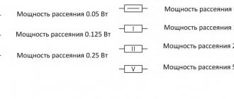
Ohm's law
- a physical law that defines the relationship between electrical quantities - voltage, resistance and current for conductors.
It was first discovered and described in 1826 by the German physicist Georg Ohm, who showed (using a galvanometer) the quantitative relationship between electromotive force, electric current and the properties of the conductor as a proportional relationship. Subsequently, the properties of a conductor that can resist electric current based on this dependence began to be called electrical resistance (Resistance), denoted in calculations and diagrams by the letter R
and measured in Ohms in honor of the discoverer.
The source of electrical energy itself also has internal resistance, which is usually denoted by the letter r
.
Ohm's law for a circuit section
From the school physics course, everyone is well aware of the classical interpretation of Ohm’s Law:
The current strength in a conductor is directly proportional to the voltage at the ends of the conductor and inversely proportional to its resistance.
I = U/R
This means if to the ends of the conductor with resistance R
= 1 Ohm, a voltage
U
= 1 Volt is applied, then the magnitude of the current
I
in the conductor will be equal to 1/1 = 1 Ampere.
This leads to two more useful relationships:
If a current of 1 Ampere flows in a conductor with a resistance of 1 Ohm, then at the ends of the conductor there is a voltage of 1 Volt (voltage drop).
U = IR
If there is a voltage of 1 Volt at the ends of the conductor and a current of 1 Ampere flows through it, then the resistance of the conductor is 1 Ohm.
R = U/I
The above formulas in this form can be applied to alternating current only if the circuit consists only of active resistance R
. In addition, it should be remembered that Ohm's Law is valid only for linear circuit elements.
A simple online calculator is provided for practical calculations.
Ohm's law. Calculation of voltage, resistance, current, power.
After resetting, enter any two known parameters.
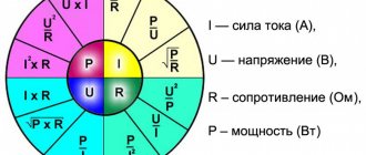
| I=U/R; U=IR; R=U/I; P=UI P=U²/R; P=I²R; R=U²/P; R=P/I² U=√(PR) I= √(P/R) |
Formula for calculating wire cross-section and how the wire cross-section is determined
Quite a lot of questions are associated with determining the cross-section of the wire when constructing electrical wiring. If we delve deeper into electrical engineering theory, the formula for calculating the cross section looks like this:
Of course, in practice, this formula is used quite rarely, resorting to a simpler calculation scheme. This scheme is quite simple: the current strength that will act in the circuit is determined, after which the cross-section is determined according to a special table. You can read more about this in the material – “Wire cross-section for electrical wiring”
Let's give an example. I have a 2000 W boiler, what size wire should it be to connect it to household electrical wiring? First, let's determine the current strength that will act in the circuit:
As you can see, the current strength is quite decent. We round the value to 10 A and refer to the table:
Thus, our boiler will require a wire with a cross-section of 1.7 mm. For greater reliability, we use a wire with a cross-section of 2 or 2.5 mm.
Ohm's law in simple words: for a section of a circuit, for a complete circuit VIDEO
The last two formulas are convenient for calculating the power of a section of a circuit if you know the R of the element I or U that falls on it.
Expert opinion
It-Technology, Electrical power and electronics specialist
Ask questions to the “Specialist for modernization of energy generation systems”
How does the current strength in a conductor depend on the resistance of this conductor? Finding the power in a three-phase network is also easy; to determine the total S, use the calculation formula for current and phase voltage. Ask, I'm in touch!
Ohm's law for a closed circuit
R to the power source
, current will flow in the circuit taking into account the internal resistance of the source:
I
— Current strength in the circuit.
— Electromotive force (EMF) is the magnitude of the power source voltage independent of the external circuit (without load). Characterized by the potential energy of the source. r
— Internal resistance of the power supply.
For electromotive force, external resistance R
and internal
r
are connected in series, which means the amount of current in the circuit is determined by the value of the EMF and the sum of the resistances:
I = /(R+r)
.
The voltage at the terminals of the external circuit will be determined based on the current strength and resistance R
by the relationship that has already been discussed above:
U = IR
.
Voltage U
, when connecting a load
R
, will always be less than the EMF by the value of the product
I*r
, which is called the voltage drop across the internal resistance of the power source.
We encounter this phenomenon quite often when we see partially discharged batteries or accumulators in operation. As the discharge progresses, their internal resistance increases, therefore, the voltage drop inside the source increases, which means the external voltage U
= -
I*r
.
internal
resistance of the source, the closer in value its EMF and voltage at its terminals U. If the current in the circuit is zero, therefore
= U. The circuit is open, the emf of the source is equal to the voltage at its terminals.
In cases where the internal resistance of the source can be neglected ( r
≈ 0), the voltage at the source terminals will be equal to the EMF ( ≈
U
)
regardless of the external circuit resistance
R. Such a power source is called a voltage source .
Current, voltage and power in an electrical circuit
Figure 1.2
Basic concepts about an electrical circuit.
DC electrical circuits.
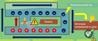
An electrical circuit is a collection of sources of electrical energy and its consumers (loads) galvanically connected to each other, in which electric current can occur. With the help of sources, one or another type of energy (energy of burned fuel, falling water, atomic and chemical energy, etc.) is converted into electrical energy.
Receivers, on the contrary, convert electrical energy into its other types (mechanical, thermal, chemical, light energy, etc.).
A graphical representation of an electrical circuit using the symbols of its elements is called an electrical circuit diagram.
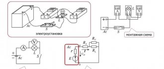
Electrical circuits are divided into branched and unbranched . The simplest unbranched chain is shown in Fig. 1.1. The same current acts in all elements of an unbranched circuit. A branched chain (Fig. 1.2) contains branches, nodes, and contours. A branch is a section of a chain consisting of elements connected in series and concluded between two nodes. Each branch has its own current.
A node is a point in an electrical circuit where at least three branches are galvanically connected. Any closed path in a diagram is called a circuit . independent if it contains at least one branch that is not included in another circuit.
An example of a branched electrical circuit is shown in Fig. 1.2. In the diagram there are two nodes designated by the letters “a” and “b”, three branches located between the nodes and two independent circuits.
Electric current and voltage are the main quantities characterizing the state of electrical circuits. Electric current in conductors represents the phenomenon of ordered movement of electric charges under the influence of an electric field. The words current also mean the intensity or strength of the current, measured by the amount of electric charge q passing through the cross section of the conductor per unit time:
,[A](1.1)
where ∆q is the electric charge passed through the cross section of the conductor during the time ∆t .
Consequently, the current characterizes the rate of change of charge over time.
In the SI system, charge is measured in coulombs (C), time is measured in seconds, and current is measured in Amperes (A).
Current is a scalar algebraic quantity, the sign of which depends on the direction of movement of like charges, namely the conventionally accepted positive charge. To unambiguously determine the sign of the current, it is enough to arbitrarily select one of two possible directions as positive, which is marked with an arrow (see Fig. 1.2.). Before starting the analysis of the electrical circuit, it is necessary to note the positive directions of currents in all branches, the choice of which can be arbitrary. The law of change of current over time can be expressed by a time function of arbitrary shape.
Constant is a current whose value is constant over time with constant parameters of the electrical circuit. Direct current is usually denoted by the letter I.
The passage of electric current in a circuit involves the conversion or consumption of energy. To determine the energy expended when moving a charge between the two points of the conductor under consideration, a new quantity is introduced - voltage .
Electrical voltage between two points is the amount of energy expended to move a charge from one point to another.
, [IN] (1.2.)
where W is the energy of the electric field. When measuring energy in joules (J) and charge in coulombs (C), voltage is measured in volts (V).
To unambiguously determine the sign of the voltage between the two terminals of the section of the circuit under consideration, one of the terminals is conventionally assigned a positive polarity, which is marked either with a <+> sign or an arrow directed from the terminal (Fig. 1.3). The voltage is positive if its polarity matches the selected one.
Typically, the conditionally positive voltage polarity is chosen to be consistent with the selected positive current voltage when the arrows for current and voltage coincide. , voltage is usually denoted by the letter U.
From the definition of voltage (1.2) we obtain an expression for the energy W spent on moving charge q in a section of the circuit with voltage U at time t :
(1.3)
Differentiating this equality in time gives an expression for instantaneous power p - the rate of change of energy over time:
(1.4)
Power is measured in Watts (W). Power in a direct current electrical circuit is denoted by the letter P and is equal to P=UI . It is an algebraic quantity, the sign of which is determined by the sign of voltage and current: if these signs coincide, the power is positive ( P >0), which corresponds to energy consumption in the section of the circuit under consideration; when the signs of current and voltage do not coincide, the power is negative ( P <0), which means that it is isolated from a section of the circuit (such a section is a source of energy).
Figure 1.2
Basic concepts about an electrical circuit.
DC electrical circuits.
An electrical circuit is a collection of sources of electrical energy and its consumers (loads) galvanically connected to each other, in which electric current can occur. With the help of sources, one or another type of energy (energy of burned fuel, falling water, atomic and chemical energy, etc.) is converted into electrical energy.
Receivers, on the contrary, convert electrical energy into its other types (mechanical, thermal, chemical, light energy, etc.).
A graphical representation of an electrical circuit using the symbols of its elements is called an electrical circuit diagram.
Electrical circuits are divided into branched and unbranched . The simplest unbranched chain is shown in Fig. 1.1. The same current acts in all elements of an unbranched circuit. A branched chain (Fig. 1.2) contains branches, nodes, and contours. A branch is a section of a chain consisting of elements connected in series and concluded between two nodes. Each branch has its own current.
A node is a point in an electrical circuit where at least three branches are galvanically connected. Any closed path in a diagram is called a circuit . independent if it contains at least one branch that is not included in another circuit.
An example of a branched electrical circuit is shown in Fig. 1.2. In the diagram there are two nodes designated by the letters “a” and “b”, three branches located between the nodes and two independent circuits.
Electric current and voltage are the main quantities characterizing the state of electrical circuits. Electric current in conductors represents the phenomenon of ordered movement of electric charges under the influence of an electric field. The words current also mean the intensity or strength of the current, measured by the amount of electric charge q passing through the cross section of the conductor per unit time:
,[A](1.1)
where ∆q is the electric charge passed through the cross section of the conductor during the time ∆t .
Consequently, the current characterizes the rate of change of charge over time.
In the SI system, charge is measured in coulombs (C), time is measured in seconds, and current is measured in Amperes (A).
Current is a scalar algebraic quantity, the sign of which depends on the direction of movement of like charges, namely the conventionally accepted positive charge. To unambiguously determine the sign of the current, it is enough to arbitrarily select one of two possible directions as positive, which is marked with an arrow (see Fig. 1.2.). Before starting the analysis of the electrical circuit, it is necessary to note the positive directions of currents in all branches, the choice of which can be arbitrary. The law of change of current over time can be expressed by a time function of arbitrary shape.
Constant is a current whose value is constant over time with constant parameters of the electrical circuit. Direct current is usually denoted by the letter I.
The passage of electric current in a circuit involves the conversion or consumption of energy. To determine the energy expended when moving a charge between the two points of the conductor under consideration, a new quantity is introduced - voltage .
Electrical voltage between two points is the amount of energy expended to move a charge from one point to another.
, [IN] (1.2.)
where W is the energy of the electric field. When measuring energy in joules (J) and charge in coulombs (C), voltage is measured in volts (V).
To unambiguously determine the sign of the voltage between the two terminals of the section of the circuit under consideration, one of the terminals is conventionally assigned a positive polarity, which is marked either with a <+> sign or an arrow directed from the terminal (Fig. 1.3). The voltage is positive if its polarity matches the selected one.
Typically, the conditionally positive voltage polarity is chosen to be consistent with the selected positive current voltage when the arrows for current and voltage coincide. , voltage is usually denoted by the letter U.
From the definition of voltage (1.2) we obtain an expression for the energy W spent on moving charge q in a section of the circuit with voltage U at time t :
(1.3)
Differentiating this equality in time gives an expression for instantaneous power p - the rate of change of energy over time:
(1.4)
Power is measured in Watts (W). Power in a direct current electrical circuit is denoted by the letter P and is equal to P=UI . It is an algebraic quantity, the sign of which is determined by the sign of voltage and current: if these signs coincide, the power is positive ( P >0), which corresponds to energy consumption in the section of the circuit under consideration; when the signs of current and voltage do not coincide, the power is negative ( P <0), which means that it is isolated from a section of the circuit (such a section is a source of energy).
Ohm's law for alternating current
If there is inductance or capacitance in an AC circuit, its reactance must be taken into account. In this case, the entry for Ohm's Law will look like:
I = U/Z
Here Z
- total (complex) resistance of the circuit -
impedance
.
It includes active R
and reactive
X
components. Reactance depends on the ratings of the reactive elements, on the frequency and shape of the current in the circuit. You can learn more about complex resistance on the impedance page.
Taking into account the phase shift φ
created by reactive elements, Ohm's Law is usually written for sinusoidal alternating current
in complex form
:
is the complex amplitude of the current. = Iampe jφ
— complex voltage amplitude.
= Uampe jφ
- complex resistance.
Impedance. φ
is the phase angle between current and voltage.
e
is a constant, the base of the natural logarithm.
j
is the imaginary unit.
Iamp, Uamp
- amplitude values of sinusoidal current and voltage.
Concept of current, power, voltage
When considering the concepts of current, voltage, power, you need to realize that all these three parameters are inextricably linked.
Power is the ratio of the work produced over a certain period of time to a given period of time.
The unit of measurement is Watt. 1 kilowatt is equal to 1000 watts. Current strength is the directed movement of charged particles. Expresses the amount of charge that runs through a conductor section per unit time. The unit of measurement is Ampere.
Voltage is the ratio of the work done by the electric field to transfer charge to the value of charge transferred on the circuit strip. This parameter expresses the work done by the field to transfer charge between two points. The unit of measurement is Volt.
It is possible to draw an analogy between the described parameters of “strength”, “power” and “voltage” with the flow of water, where the number of amperes (current strength) is the volume of water flowing per unit of time (determined by the consumption of electricity, in other words, it depends on how much the open faucet), the number of watts (power) is, for example, the action of driving the turbine blades (pressure multiplied by current), and the value of volts (voltage) is the water pressure in the pipeline. Therefore, the main thing on the power supply is the power, that is, whether the device can withstand it, on the battery - the voltage, whether the user will pull it. On devices for an electrical network with a set voltage (220 volts for us), the maximum current, when multiplied by the voltage value, is also the maximum power.
How to calculate power using voltage and current?
“Power” = “Current” (Amperes) multiplied by “Voltage” (Watts).
How to calculate current by power and voltage?
Based on the previous formula, we can find the current value:
“Current” = “Power” (Volt-amps) divided by “Voltage” (Watts).
There are a couple more significant factors when it comes to electricity:
- Typical outlets are rated at 16 amps. So, since the voltage in the electrical network is 220 volts, this means that the limiting power is equal to: 16 amperes multiplied by 220 volts = 3520 watts (3.52 kilowatts). — In the production of sockets, 16-amp circuit breakers are mainly used. It follows from this that when the current on a power line with a 16-amp circuit breaker exceeds 16 amperes (or the power increases above 3.52 kilowatts), the device will automatically turn off.
In particular, if your house has an individual line for kitchen outlets, then when two electric heaters, both with a power of 2 kilowatts, are connected to this line at once, the machine will disconnect the electrical circuit.
Nonlinear elements and circuits
Ohm's law is not a fundamental law of nature and can be applied in limited cases, for example, for most conductors. It cannot be used to calculate voltage and current in semiconductor or vacuum devices, where this dependence is not proportional and can only be determined using the current-voltage characteristic (volt-ampere characteristic). This category of elements includes all semiconductor devices (diodes, transistors, zener diodes, thyristors, varicaps, etc.) and vacuum tubes. Such elements and the circuits in which they are used are called nonlinear.
Similar articles: Direct current. Alternating current.
Comments and suggestions are accepted and welcome!
Calculation of voltage, current and resistance
Ohm's law is designed to find the unknown third if the first and second are known. From this point on, in order to simplify Ohm's law, we will use Ohm's triangle. This is the triangle:
Here is the formula: U=I*R , where U is voltage, I is current, R is resistance.
Now let's try to find the current, cover I , now in front of the voltage and resistance there is a horizontal line, horizontal is the line that goes from left to right. A horizontal line means division. This means that to find the current, you need to divide the voltage by the resistance.
The formula is as follows: I = U\R , where I is current, U is voltage, R is resistance.
Let's find the resistance, close R , then we will again get a horizontal line in front of the voltage and current, which means we need to divide.
The formula for calculating resistance is: R=U\I , where R is resistance, U is voltage, I is current. So, we learned how to use Ohm's triangle and learned about Ohm's Law. Now, perhaps, let's learn from examples.
Expert opinion
It-Technology, Electrical power and electronics specialist
Ask questions to the “Specialist for modernization of energy generation systems”
How to calculate the current consumed by a household appliance? Everyday life of a radio amateur For example, if we connect a washing machine with a resistance of 40 Ohms to a 220 V outlet, we will find out that the machine consumes a current of 5.5 A. Ask, I’m in touch!