As you know, no load more powerful than an LED can be connected to the Arduino directly, especially motors. Arduino, and indeed any microcontroller in general, is a logical device that can only give logical signals to other pieces of hardware, and they can already control the load. By the way, I also have a lesson on managing powerful DC and AC loads. The “driver” of the motor can be different pieces of hardware, let’s look at some of them.
Relay
Using a regular relay, you can simply turn the motor on and off using the digitalWrite(pin, state) command, just like an LED:
Using a double relay module (or just two relays), you can turn the motor on in one direction or the other, as well as turn it off:
You can buy a relay module Relay aliexpress, aliexpress, search
Mosfet
A field-effect transistor, also known as a mosfet, allows you to control the rotation speed of the motor using a PWM signal. When using a mosfet, you must install a diode, otherwise the inductive surge from the motor will very quickly kill the transistor. The motor speed can be set using Arduino analogWrite(pin, speed).
Instead of a “bare” mosfet, you can use a ready-made Chinese module:
You can buy a mosfet module on Aliexpress: Mosfet module aliexpress, aliexpress, search
Relay and mosfet
If we combine a relay and a mosfet, we get a very collective farm, but working scheme for controlling the speed and direction of the motor:
Special driver
It is best to control the motor using a special driver; they come in different shapes and sizes and are designed for different voltages and currents, but they are controlled almost the same. Let's look at the main drivers from the Chinese market:
| Driver | Vmot | Current (peak) | ~Cost | Aliexpress |
| L298N | 4-50V | 1A (2A) | 100r | Buy |
| MX1508 | 2-9.6V | 1.5A (2.5A) | 20r | Buy |
| TA6586 | 3-14V | 5A (7A) | 100r (chip 30r) | Buy |
| L9110S | 2.5-12V | 0.8A (1.5A) | 50r | Buy |
| TB6612 | 4.5-13.5V | 1.2A (3A) | 80r | Buy |
| BTS7960 | 5.5-27V | 10A (43A) | 300rub | Buy |
| Big | 3-36V | 10A (30A) | 700rub | Buy |
See my other drivers here. Connection diagrams and control tables:
Direction pins are controlled using digitalWrite(pin, value), and PWM is controlled using analogWrite(pin, value). There are two options for controlling the driver using two pins:
// === first type, most common === // forward digitalWrite(pinA, 0); analogWrite(pinB, value); // value 0.. 255 // back digitalWrite(pinA, 1); analogWrite(pinB, 255 - value); // value 0.. 255 // === second type, for example large driver === // forward digitalWrite(pinA, 0); analogWrite(pinB, value); // value 0.. 255 // back digitalWrite(pinA, 1); analogWrite(pinB, value); // value 0.. 255 // the difference is that the PWM does not need to be inverted like 255 is a value!
Interference and protection against it
Inductive voltage surge
The motor is an inductive load that creates inductive surges when switched off. The motor has brushes, which are a source of sparks and interference due to the same inductance of the coil. The motor itself does not consume energy very evenly, which can cause interference along the power line, and the starting current of the motor is generally much higher than the operating current, which is guaranteed to drain the weak power supply during startup. All four sources of interference can lead to various glitches in the operation of the device, including the activation of buttons on digital pins, interference on analog pins, sudden freezing and even rebooting of the microcontroller or other hardware in the device assembly. You can cut off inductive emissions from the motor using the most ordinary diode; the more powerful the motor, the more powerful the diode is needed, that is, for a higher voltage and current. The diode is placed counter parallel to the motor, and the closer to the body, the better. It is recommended to do exactly the same with solenoid valves, solenoids, electromagnets and any other coils in general. It is logical that a diode should be installed only if the motor or coil is controlled in one direction. Important points:
- When working with the driver and control, it is not necessary and even impossible to install a diode in both directions!
- When controlling a PWM signal, it is recommended to install high-speed diodes (for example, 1N49xx ) or Schottky diodes (for example, 1N58xx ).
- The maximum diode current must be greater than or equal to the maximum motor current.
- A protective diode that absorbs the reverse surge of self-induction EMF is also called a shunt diode, snubber, flyback diode.
- In nature, there are mosfets with a built-in protective diode. This diode is a separate element and such a mosfet usually has a non-standard case; read the documentation for the specific transistor.
- The diode that is shown in the schematic diagram of the mosfet is not a protection diode: it is a weak and slow “parasitic” diode formed during the production of the transistor. It will not protect the mosfet from emission; you must install an external one!
Interference from brushes
The sparkling brushes of a motor, especially an old and broken one, are a strong source of electromagnetic interference, and here the problem is solved by installing ceramic capacitors with a capacity of 0.1-1 uF on the motor terminals. The same capacitors can be placed between each terminal and the metal case, this will further suppress the interference. To solder to the body, you need to use a powerful soldering iron and active flux to tin and solder as quickly as possible without overheating the motor.
Power supply interference, drawdown
The motor does not consume current very evenly, especially during acceleration or under conditions of variable load on the shaft, which manifests itself in the form of voltage drops in the power supply to the entire circuit. Problems with power supply can be solved by installing capacious electrolytic capacitors for power supply; it is logical that they should be installed as close as possible to the driver, that is, before the driver. The voltage must be higher than the supply voltage, and the capacity is already selected according to the fact. You can start with 470 uF and increase until it feels good.
Power sharing
If the methods described above do not help, there is only one thing left: power sharing. A separate low-noise good source for the MK and sensors/modules, and a separate one for the power part, including the motor. Sometimes, for the sake of stability, it is necessary to introduce a separate power supply or a separate battery for reliable operation of the device.
Shielding
In some cases, even interference from the supply wires of motors is critical, especially when controlling PWM powerful motors and controlling powerful steppers in machine tools. Such interference can create strong interference for sensitive electronic components operating nearby, on analog circuits, interfere with ADC measurement lines and, of course, interfere with radio communications. You can protect yourself from such interference by shielding power wires: it’s not always possible to buy shielded power wires, so it’s enough to wrap regular wires with foil and connect the screen to GND of the power supply. This trick is often used by RC modelers flying FPV.
Types of motors for use in Arduino What is there anyway?
You can choose the following engines for your projects to use on the Arduino board.
Get to know each of them using their contact details:
motor doctor
It is a direct current motor , also called DC because it is direct current. Its main characteristic is the conversion of electrical energy into mechanical energy thanks to a magnetic field . This means that the motor rotates continuously in both directions if the polarity of the current is reversed.
It consists of a stator ; which is used to create poles and usually consists of magnets or copper wires; and rotor . This last component accepts direct current and is cylindrical in shape made of graphite or other alloys. Its main applications are linear motors, stepper motors and servo motors. They can very often be found in toys. because their speed can be controlled.
Servo motor
A servo motor is a special type of motor that is used to hold an axle in one place so they can be rotated 180° or made a full rotation. Characterized by high torque. is generated by its potentiometer , which works with the DC motor and is used to move the gears.
Par Serial Servo Motor is a box consisting of an Arduino board , potentiometer, DC motor and gears. It is primarily used in robotics, which is why it can be seen in factories, toys, and even elevators.
Driver L293D
This device's job is to control other motors , making it ideal for Arduino projects. It can work with 4 DC motors or 2 stepper motors or if you prefer 2 servo motors. . This means there can be a combination of them if your terminal blocks allow it. Including individual circuits , you can control how much load each motor will receive.
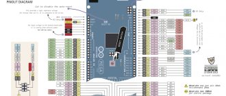
It can be used on Arduino UNO board according to the following pins:
- Digital 3 - PWM_Motor2
- Digital 4 - DIR_CLK
- Digital 5 - PWM_Motor4
- Digital 6 - PWM_Motor3
- Digital 7 - DIR_EN
- Digital 8 - DIR_SER
- Digital 9 - Servo_1
- Digital 10 - Servo_2
- Digital 11 - PWM_Motor1
- Digital 12 - DIR_LATCH
L298 pilot
This component is responsible for controlling the speed and direction of rotation of the motors during rotation. It is characterized by compatibility with a wide temperature fonctionnement range, from 20 ° C to + 135 ° C. The output current generated per channel can be up to 2 amperes .
The pin connection looks like this:
- Pin IN1 - MOTOR A
- Pin IN2 - MOTOR A
- Pin IN3 - MOTOR B
- Pin IN4 - MOTOR B
- Spindle ENA - PWM
- ENB pin - PWM
Brushless DC Motor
It is also known as a brushless motor because it does not require slip rings. change the polarity. It is characterized by its light, without requiring much entretien and being less expensive in production costs .
La difficulty in handling it has decreased in recent times, making it a widely used tool in technology. To find the correct polarity, magnetic field detection is used using a rotor. Its mechanism is found in the trays of DVD players and disc coolers. report this ad
Important Pages
- GyverKIT kit - a large Arduino starter kit of my design, sold in Russia
- Catalog of links to cheap Arduins, sensors, modules and other hardware from AliExpress from trusted sellers
- A selection of libraries for Arduino, the most interesting and useful, official and not so
- Complete documentation on the Arduino language, all built-in functions and macros, all available data types
- A collection of useful algorithms for writing sketches: code structure, timers, filters, data parsing
- Video lessons on Arduino programming from the “Arduino Engineer's Notes ” channel are some of the most detailed in RuNet
- Support the author for his work on the lessons
- Feedback - report an error in the lesson or suggest an addition to the text ( [email protected] )
4.5 / 5 ( 11 votes)
Connecting the L298N driver to Arduino Uno
To try the driver in action, let's connect it to the Arduino Uno controller and to any small DC motor that comes to hand. In this lesson we use the simplest motor with a supply voltage of 1.5-3 Volts. To power this motor, two AA batteries will be enough for us. In such a circuit, it is simply impossible to power the driver chip from the built-in stabilizer, so we will take +5V power from Arduino.
We also note that with this connection diagram with an external +5 V power supply, we need to remove the corresponding jumper that we talked about above (the power jumper from the stabilizer)!
Well, since we plan to control the rotation speed, we will remove the jumper from the ENA contact.
Schematic diagram
Layout appearance
Best Motorized Arduino Projects You Can Make From Scratch
The best motorized Arduino projects can be found in this list:
Brushless DC Motor Drive
You will need an Arduino Nano R3 type board , then a brushless DC motor and coils to get to the drive.
Transmitter codes:
# turns on Servo esc; HC12 series software (2, 3); // reception, transmission int th, garlic, ele, rudd; void param() { tie(10); pinMode(A0, INPUT); Serial. start(9600); start(9600); } empty loop() { th = map(analogRead(A0), 0, 1023, 0, 180); print(th); Serial. print(th); delay(100); }
You will need to use the following software codes for the receiver:
# turns on Servo esc; String entry; int accelerator, th; void param() { tie(10); Serial. start(9600); start(9600); write (170); delay(2000); write(90); delay(2000); write(140); delay(2000); write(90); delay(2000); } empty loop () { yes (String. available ()) { butterfly = Series. readStringUntil('\n'); if (input.length() > 0) { write(accelerator); delay(10); } } }
Motor with potentiometer
For this Arduino project you need an Arduino UNO, one motor one rotary potentiometer, one insert plate , 10K Ohm resistance LED and cables.
Once all components are connected, you will need to enter these codes:
# define MOF_PIN 6 #define POT_PIN A1 pot int = 0; void param() { pinMode(MOF_PIN, OUTPUT); pinMode(POT_PIN, INPUT); Serial. start(9600); } empty loop() { pot = analog read(POT_PIN); Serial. println(boat); AnalogWrite(MOF_PIN, pot/4); }
Stepper motor driver
A driver is a device that connects the controller and the stepper motor. To control a bipolar stepper motor, the L298N and ULN2003 drivers are most often used.
Operating the motor in bipolar mode has several advantages:
- Increased torque by 40% compared to unipolar motors;
- Possibility of using motors with any phase winding configuration.
But a significant disadvantage in bipolar mode is the complexity of the driver itself. The unipolar drive driver requires only 4 transistor switches; a more complex circuit is required to ensure the operation of the bipolar drive driver. With each winding you need to carry out various actions separately - connecting to the power source, disconnecting. For such switching, a bridge circuit with four keys is used.
Stepper motor driver based on L298N
This bridge driver controls the motor with current up to 2A and power supply up to 46V. The L298N driver-based module consists of the L298N chip, cooling system, terminal blocks, signal connectors, voltage regulator and protection diodes.
L298N motor driver
Stepper motor driver ULN2003
Description of the UNL2003 stepper motor driver
Stepper motors with driver modules based on ULN2003 are frequent guests in Arduino workshops due to their low cost and availability. As a rule, this comes at the price of not very high reliability and accuracy.
Other drivers
There is another type of driver - STEP/DIR drivers. These are hardware modules that operate using the STEP/DIR protocol to communicate with the microcontroller. STEP/DIR drivers expand the capabilities of:
- They allow you to stabilize phase currents;
- Possibility of setting microstepping mode;
- Ensuring protection of the key from short circuit;
- Overheat protection;
- Opto-isolation of the control signal, high immunity to interference.
STEP/DIR drivers use 3 signals:
- STEP is an impulse that initiates a turn by step/part of a step, depending on the mode. The engine rotation speed will be determined from the pulse repetition rate.
- DIR is a signal that specifies the direction of rotation. Typically, when a high signal is applied, it rotates clockwise. This type of signal is generated before the STEP pulse.
- ENABLE – enable/disable driver operation. Using this signal, you can stop the motor in mode without holding current.
One of the most inexpensive STEP/DIR drivers is the TB6560-V2 module. This driver provides all the necessary functions and modes.
What should I keep in mind when choosing the ideal motor for my Arduino project?
Before choosing a motor for your Arduino project, you should consider the following factors:
- Spin speed time. In other words, you will need to understand what the optimal speed of the motor is for your project.
- Force applied to mass , also called steam in rotary engines. You need to take into account whether the weight of the object you want to move will be more or less than the motor power required to move it.
- Possibility of supplying an electric charge. In other words, you must consider the amount of energy that the engine is capable of delivering at a given time.
- Maximum work possibilities. This has to do with the load the engine must handle without breaking down due to the force being applied.
- The level of precision is another factor to consider, as the movements you'll need in your project may require varying degrees of precision.
- Supply voltage. When it comes to electronics, it is important that you know that the motor operates at different voltages, so the Arduino board must provide the same voltage rating.
- Rated current. This item refers to the amount of current the motor requires to operate. To determine operating logic values, resistance and voltage ratings must be taken into account.
- The energy absorbed by the engine at any given time. This is called electrical energy and measures the overall performance of the motor on the Arduino board.
In addition to the values mentioned above, you will need to take into account the dimensions of the motor to see if it fits in the space, mounting brackets , weight and life expectancy, among other factors. By this we mean that to choose the ideal motor in your Arduino project, need to consider many factors because you may find an actuator that has a higher value than another, which does not mean that it is the best one or the one you need.
Example sketch for control
In the set of examples of the Stepper.h library, there is a program stepper_oneRevolution, in which all parameters for the stepper motor are set - the number of steps, speed, rotation.
#include const int stepsPerRevolution = 200; Stepper myStepper(stepsPerRevolution, 8,9,10,11); //connect to pins 8...11 on Arduino void setup() { myStepper.setSpeed(60); //setting the rotor rotation speed Serial.begin(9600); } void loop() { //The function waits for a command to arrive, converts the text and sends a signal to the motor to rotate it the specified number of steps. Serial.println("Move right"); //clockwise myStepper.step(stepsPerRevolution); delay(1000); Serial.println("Move left"); //counterclockwise myStepper.step(-stepsPerRevolution); delay(1000); }