Thermocouples (TC) function in many thermal processes as primary temperature sensors of an automatic safety and control system. At household heat power facilities, they are installed to protect burners from flame separation on gas boilers, water heaters and stoves, for cooking.
They operate in the high-temperature zone of the gas torch, and therefore may fail. At the same time, the automatic safety system instantly turns off gas-using equipment. In order to ensure trouble-free and long-term operation of gas stoves, water heaters and boilers, it is necessary to exclude false triggering of the protection, and you also need to know how to test a thermocouple with a multimeter. This can be done at home without any problems.
What is a thermocouple
A thermocouple is a device consisting of soldered dissimilar conductors or semiconductors that form a single electrical circuit. TC works on the basis of the thermoelectric effect known as the “Seebeck effect”.
An effect when two dissimilar metals welded together at a certain temperature generate a voltage proportional to the resulting thermal energy. The higher the temperature difference at the junction point, the more the thermocouple produces E.M.F.
Advantages and disadvantages of using thermocouples
The advantages of using this device are:
- Large temperature measurement range;
- High accuracy;
- Simplicity and reliability.
The disadvantages include:
- Carrying out continuous monitoring of the cold junction, verification and calibration of control equipment;
- Structural changes in metals during the manufacture of the device;
- Dependence on the composition of the atmosphere, costs of sealing;
- Measurement error due to exposure to electromagnetic waves.
Design
The operating efficiency and high accuracy of operation of this primary temperature sensor is based on a simple principle.
Its operation is ensured by the following basic design elements:
- A thermocouple junction made of 2 dissimilar conductors. Sometimes semiconductors can be installed instead of conductors.
- Insulated conductors that make up the circuit from the soldering point to the point where the signal is output to external current collectors.
- Shielding protective coating is a metal tube that covers the circuit wires from exposure to open fire in a gas torch.
Important! The composition of the junction can include both non-ferrous and noble metals. Depending on this, thermocouples are grouped into several modifications, the characteristics of which are presented below.
Device, principle of operation and main types
A thermocouple is a classic thermoelectric converter that is used to measure temperature in various fields of industry, science, medicine, as well as in automatic control and monitoring systems for gas boilers, stoves and water heaters.
It is designed very simply and can easily be made independently. Two conductors made of different materials are connected into a ring. One of the connection points is placed in the measurement area, and the second is connected to the measuring instrument or converter device.
Photo 1: Thermocouple for gas control device
The operating principle of a thermocouple is based on the thermoelectric effect, or as it is also called the Seebeck effect. It lies in the fact that voltage appears at the junction of two conductors made of different metals connected in a ring. If the temperature of the adhesion sites is the same, the potential difference is zero. But as soon as one of the junctions is placed in an area with a higher or lower temperature, a voltage appears that is different from zero and proportional to the temperature difference. The proportionality coefficient is different for different metals and is called the thermo-EMF coefficient.
Photo 2: Design and principle of operation of the thermocouple
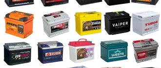
The main materials for the manufacture of thermocouples are noble and base metals. Most of their alloys have rather exotic names, which are very popular among the compilers of various crosswords and scanwords. Depending on what metal pairs are used in manufacturing, thermocouples are divided into several types. Below is a table with their main types, designations and characteristics:
Thermocouple typeAlloyRussian markingTemperature range, °C
| K | chromel-alumel | THA | -200 — 1300 |
| J | iron-constantan | TZHK | -100 — 1200 |
| N | nikhrosil-nisil | TNN | -200 — 1300 |
| R | platinum-rhodium-platinum | Chamber of Commerce and Industry13 | 0 — 1700 |
| S | platinum-rhodium-platinum | TPP10 | 0 — 1700 |
| B | platinumrhodium-platinumrhodium | TPR | 100 — 1800 |
| T | copper-constantan | TMKn | -200 — 400 |
| E | chromel-constantan | THKn | 0 — 600 |
| U | copper-copper-nickel | -200 — 500 | |
| L | chromel-copel | THC | -200 — 850 |
In automatic systems for geysers, stoves and boilers, thermocouples TCA made of chromel-alumel (type K), TCA from chromel-copel (type L), TLC made of iron and constantan (type J) are usually used. Sensors made of noble metal alloy are designed for high temperatures and are mainly used in foundries and other heavy industries.
Photo 3: Sakhalin gas burner for heating boilers and furnaces
Some models operating on solid fuel, for example, such as the solid fuel heating boiler “Lemax” Forward, can be equipped with gas burners, which use thermocouples to protect against gas leaks.
Principle of operation
The thermocouple is installed in the high temperature zone being measured. The metal alloy is heated to operating temperature. Voltage develops between cold and hot connections in a circuit. A current collector or measuring device is connected to the cold leads of the thermocouple, thereby completing the circuit. The voltage that arises in the coil of the electromagnetic type gas shut-off valve creates induction, causing it to open and allow gas to flow to the burner.
In order to start the boiler or geyser, you will first need to press the rod in manual mode. Gas will begin flowing to the burner and the piezo igniter will ignite the torch. The thermocouple will heat up within 30 seconds. When the thermocouple generates operating voltage, the solenoid valve will be held open by this voltage. After the gas stops entering the furnace or an emergency separation of the torch from the burner occurs, the thermocouple junction cools down and the supply of voltage to the gas valve stops, which closes, thereby cutting off the fuel supply to the boiler or gas water heater.
Reference. According to this principle, the safety system operates not only in domestic gas installations, but also at powerful energy plants from thermal power plants to nuclear power plants, as well as in metallurgical, chemical and other types of industries that use gas in technological processes.
Probes for SMD mounting and alligator clips
When producing SMD installations, you have to periodically take measurements. For the convenience of this process, the multimeter should have thinner probes. These devices have needle-shaped tips made of stainless steel or brass. These tips are very sharp and must always be capped to protect the user from injury and prevent electrode breakage.
Alligator clips
These probes are very convenient for piercing the insulating layer of the wire, as well as for cleaning the solder mask from the surface of the board for further measurements. The advantage of such probes is the ability to measure in an electrical network with a voltage of 600 volts.
There are also tester probes for these types of work. They have the ability to measure the necessary indicators, both on the desktop and on the board. In this case, the SMD components are clamped with pliers, which ensure effective contact.
Such probes have a very short wire, but for these types of work a long cable is not very convenient. To avoid touching other parts when taking measurements, it is necessary to use probes with holes at the ends. These holes help to take measurements on printed circuit boards, and also eliminate short circuits during electrical installation work.
Alligator clips are also in very high demand among craftsmen. In some cases, they are even more effective than sharp electrodes. Their sizes can vary, but they must always be in a dielectric shell.
Why do you need to check thermocouples?
Any power unit will be switched off in an emergency if the temperature sensor does not work. Replacing a thermocouple is an expensive process, especially since it is not needed in all cases. To exclude false triggering of the safety automatics by the flame, it is better to check the TP. Restoring its functionality begins with a visual inspection of the thermocouple.
As a rule, it fails due to the thermal indicator burnout, which happens quite often in boilers. In this case, a black dent or even a through hole can be found on the surface of the sensor. In this case, such a meter is immediately rejected and a new one will need to be installed.
Important! In some cases, the thermocouple has no external deviations. In this case, its performance can only be checked using a multimeter.
Operating principle of the boiler
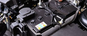
The connection diagram of the thermoelectric sensor in various gas-using devices is approximately the same. The measuring electrode is located in the area of action of the wick or the main burner, the conductor is connected to an electromagnet that opens the gas supply.
How does a thermocouple work on floor-standing boilers of the AOGV type and similar devices:
- The user presses the button with one hand and forcibly opens the gas supply solenoid valve.
- With the second hand, the homeowner turns on the piezo ignition while holding the first key. The pilot lights up.
- According to the operating instructions, the button must be held for 5-30 seconds (depending on the model of the unit), during which the wick warms up the measuring electrode.
- A direct current appears in the electromagnet circuit, coming from the thermoelectrodes. The user releases the key, but the fuel supply does not stop - the valve now holds the thermocouple voltage.
If, for various reasons, the fire goes out, heating of the thermoelement ends, and the EMF disappears. The electromagnet will turn off, the spring will close the valve and block the path of fuel.
The thermocouple electrode is located next to the igniter on all water heaters.
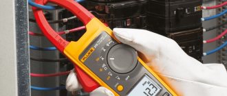
Which device to choose for measurement
To perform thermocouple testing, the simplest multimeter, which is usually available in the arsenal of a home craftsman, is suitable. If you need to buy a new one, it is better to take a model capable of solving many problems, including measuring temperatures.
You also need to pay attention to the fact that the multimeter, in addition to standard measurements of voltage, resistance and conductivity of electrical circuits, has the following functions:
- “HOLD” – function of fixing measurement results on the display;
- “REL” is a function that performs a measurement relative to a base value;
- ●))) - function for testing electrical circuits with an audible signal.
Important! The multimeter must be safe to use. Data on its electrical safety are indicated in the manufacturer's instructions and applied to the device body. To test a thermocouple, CAT II / III class instruments are sufficient, corresponding to electrical safety for in-house distribution networks and local power networks.
You can also check the thermocouple with an avometer - this is a device of a combined operating principle. Mainly measures constant current, resistance and voltage characteristics. In essence, the name “avometer” is collected from the names of 3 devices that are traditionally used to measure the noted parameters: ammeter, voltmeter, ohmmeter.
Connection and testing
The thermocouple must be connected using electrodes (wires) made of the same material as the thermocouple being connected.
Or metal wires can be used, which have characteristics similar to those of the electrodes on the thermocouple itself.
Before connecting thermocouples for heating boilers, it is important to strip the ends of the wires to remove oxides that affect the accuracy of the measurements. And during installation, it is important to ensure that the fuel outlet and supply pipes are lowered straight down.
If the thermocouple breaks, as a rule, it is no longer possible to restore it, so it is important to know how to check it with a thermocouple multimeter on a gas boiler.
The working thermocouple should operate after 10-30 seconds of heating
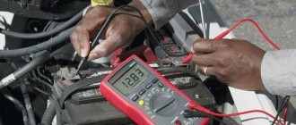
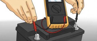
To check its functionality, just connect one end to a multimeter - a measuring sensor, and heat the other end using a gas burner or lighter.
A combined electrical measuring instrument, which can be digital and analog, combines several functions (at least the functions of a voltmeter, ohmmeter, ammeter). Multimeter
The working thermocouple should have a voltage around 50 mV.
If a thermocouple malfunction is confirmed, you can replace it yourself.
Step-by-step instructions for checking a thermocouple
Testing a thermocouple with a tester is not difficult. However, it does come with certain risks due to the presence of heat, gas and dangerous voltage. Therefore, the user must adhere to the following rules when working:
- The work area should be well lit.
- Do not use the multimeter near flammable or explosive substances, or in a room with high humidity.
- The multimeter should be on a level surface. During testing, the probes must be held by their insulated parts.
- It is forbidden to overload the multimeter during operation.
Attention! When testing a thermocouple, its body can become very hot up to the middle of the body length, so work is carried out with protective gloves.
The principle of checking a thermocouple with a multimeter is the same, but there may be some differences depending on the design of the gas-using equipment, for example, for a boiler or gas stove.
Installation device for thermocouple welding
Attention! When repeating and operating the proposed installation for welding thermocouples, due to the lack of galvanic isolation of contacts for connecting a thermocouple, it is necessary to observe the polarity of connecting the installation to the electrical wiring. Only the neutral wire must be connected to the thermocouple. Touching a phase wire may result in electric shock.
There are several ways to weld thermocouples: in an electric arc, in a salt electric welding machine, using an acetylene torch and in graphite or carbon powder. I weld thermocouples to measure temperature using LATR and a ceramic container filled with graphite powder. The technology is simple, does not require special equipment or experience and is accessible to any home craftsman.
I inherited a homemade installation for welding thermocouples, shown in the photo. The installation is a metal box in which an LATR, an alternating voltage voltmeter and a ceramic glass for graphite powder are installed.
The electrical diagram of the installation is presented above. The supply voltage is supplied through an electrical plug from household electrical wiring through a switch and fuse for a current of 5 A to the primary winding of a laboratory autotransformer. The neon lamp HL1 serves to indicate the switched on state of the installation. Resistor R1 limits the current through HL1.
At the bottom of the ceramic bowl filled with graphite powder, there is a copper plate to supply current, to which supply voltage is supplied through a brass screw from the alternating contact of the LATR. The neutral wire coming from the power plug is connected to the common wire of the LATR and to the thermocouple being welded using an alligator clip.
The amount of welding current depends on the voltage. For this purpose, the installation has an alternating voltage voltmeter, indicated in the diagram by the letter V. The voltage value is set by rotating the LATR knob and is selected experimentally depending on the diameter of the wires being welded and lies in the range of 20-90 V. There are no special elements in the circuit that limit the amount of current. It is limited by the cross-section of the circuit wires and the resistance value of the graphite powder.
The photo shows the front panel of the thermocouple welding installation from the back side. As you can see, the LATR is fixed directly to the bottom of the box, and all other elements of the electrical circuit are fixed directly to the panel.
To weld a thermocouple on the installation, it is enough to twist the conductors, clamp them with a crocodile and smoothly touch the graphite surface. An electric arc will occur, releasing a large amount of thermal energy at one point. The conductors begin to melt, and the molten metals, mixed with each other, form a neat ball, as in the photograph, due to the forces of surface tension in the liquids.
Welding time usually does not exceed three seconds. The burning of the arc is accompanied by a characteristic hissing sound, with a decreasing frequency over time. If you have experience, you can easily determine the end of the welding process by sound. Due to the large mass of the thermocouple for the gas water heater, it took about five seconds to weld it.
Here is a photo of a chromel-alumel thermocouple made of ∅0.5 mm wires, the welding of which is demonstrated in the video above. As you can see, a neat round junction has formed at the place where the wires were welded. This thermocouple will last a long time.
On a thermocouple welding machine, I mainly have to weld chromel-copel (TCA, Type L) and chromel-alumel (TCA, Type K) thermocouples with a conductor diameter of 0.2-0.5 mm. It happened during repairs that even a K-type thermocouple with a conductor diameter of 3 mm was welded. Copper and aluminum wires with a diameter of up to 2.5 mm are well welded together. But when installing electrical wiring, it is difficult to use the installation for welding connections due to its overall dimensions.
To protect the eyes from bright light when visually monitoring the welding process, it is inconvenient to use glasses or a welder’s protective mask, so I use a high-density neutral density filter from the camera.
As practice has shown, with the help of a simple installation, which is an LATR and a ceramic bowl with graphite powder, you can successfully repair thermocouples used in gas water heater automation systems at home with your own hands.
Heating gas boiler
If the gas boiler is stopped abnormally, and the boiler diagnostics informs the owner that there is no flame on the burner, then the first thing you need to do is check the functionality of the thermocouple with a multimeter:
- For safety reasons, disconnect the boiler from the electrical and gas networks.
- The thermocouple has a loose end, which is located in the burner flame, and the second is secured to the solenoid valve with a nut.
- To remove the TP from the boiler, unscrew the nut.
- The free end of the TP is heated over an open flame source. A burning candle or gas burner will do. In this case, it is important to maintain the minimum level of TP placement - 1 cm from the flame.
- After the TP has warmed up, testing with a multimeter begins.
- Set the multimeter to the mode for measuring the minimum constant electrical voltage.
- The tube has a conductive contact; you need to connect the “+” probe of the multimeter to it.
- Connect the minus probe to the element body.
- Heat the tip over an open flame.
- If the readings are within 20–25 mV, then the thermocouple is working, and malfunctions of the boiler according to this protection parameter can be caused by poor contacts between the TP wires and the gas shut-off valve.
- Even if the TC voltage does not reach 20 mV, in order to eliminate the error, you will need to ring the thermocouple several times, additionally heating it. If all measurements show results below 20 mV, then the thermocouple must be replaced, since modern sensors of this class cannot be repaired.
In order to correctly select a new TP for replacement, you need to be guided by the brand of the boiler, since the thermocouple can be produced according to the EU classification, and not according to domestic standards, and this creates a certain confusion.
Instructions for diagnostics, repair and replacement
How to test a thermocouple for functionality
It is often possible to determine that the thermocouple is faulty even visually, without disassembling the boiler. During ignition, after releasing the solenoid valve button, it will not remain in the clamped position, since the solenoid valve does not receive the minimum required voltage. The valve will close and the gas supply will stop.
You can bypass the thermocouple by holding the button with a heavy object or taping it with tape, which is often done in practice. However, we strongly do not recommend doing this, because if the flame dies out, for example, when blown out by the wind, the supply will remain open, the gas will not be burned and will enter the room, which will cause an emergency. You can resort to such a bypass only temporarily, until the arrival of a specialist or a spare module, by constantly being at the boiler and monitoring the presence of a flame.
To ensure that it is working properly or malfunctioning, you should check the thermocouple with a multimeter (tester) set to mV or a voltmeter:
- Unscrew the nut securing the thermocouple in the socket of the electromagnetic gas valve.
- Remove the working part of the thermocouple from the cat.
- Now you need to heat the working part of the thermocouple so that it generates voltage. It is best to do this over a stove burner or a candle; the flame should tightly envelop the thermocouple.
- After heating the thermocouple (30-60 seconds), apply one tester probe to the thermocouple body, and the second to the output contact. It is better to carry out measurements within 40-60 seconds, without stopping heating the working junction.
A working thermocouple of a gas boiler should produce a voltage of 20 mV (0.02 V). Some models can output up to 50-60 mV. If the thermocouple produces less than 20 mV, this is guaranteed to indicate a malfunction. However, do not rush to repair or replace the module.
How and in what cases can it be restored?
The thermocouple is designed in such a way that any damage or contamination can reduce the voltage it produces below a critical level. A very common cause of malfunction is carbon deposits or a layer of soot on its working (heated) part. To restore the thermocouple, just clean it with a soft brush or cotton wool and alcohol, while avoiding scratches and other damage. After cleaning, it is worth checking the voltage again following the instructions above.
Oxidized contacts are also a common cause; they can be carefully treated with sandpaper. If the thermocouple has a deep black dent or hole due to burning, it is guaranteed to need to be replaced.
Gas stove
All modern gas stoves have a gas control system that works with a thermocouple. In the case when the stove does not start due to the activation of protection for this indicator, most likely the thermocouple is clogged or faulty.
Important! Before starting testing, you need to turn off the gas supply to the burners and oven, disconnect the stove from the power supply and remove all utensils and utensils.
Step-by-step instructions for checking the functionality of a thermocouple with a multimeter in gas stoves:
- Remove the door from the oven.
- Find TP. It is usually located near the flame divider.
- If, during an external inspection, dirt and soot were found on the surface of the thermocouple body, then carefully remove it with fine sandpaper.
- Remove any debris from the oven. Check the functionality of the sensor again.
- If the gas stove is still turned off by the protection system, then proceed to check the TP with a multimeter.
- To do this, you need to find the power line connecting the sensor to the electrical protection of the stove. As a rule, it is located under the front panel or under the top cover at the location of the gas shut-off valve and temperature switch.
- They check the integrity of the contact group, which can also malfunction the TP.
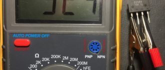
- Set the measurement limit of the device in the region of tens of mV.
- Connect the probes to the thermocouple terminals and heat the measuring section.
- If the multimeter shows voltages at the TC terminals up to 20 mV, the device is not working properly. To ensure accurate determination, measurements are performed several times.
Description and characteristics
A thermocouple is a device consisting of two different conductors that are connected at one or more points by compensation wires. When a temperature measurement occurs at one end of the wire, a voltage of a certain value and strength is created at the other. This device is used to control temperature and also to convert temperature into electrical current.
Making a thermocouple at home is not difficult. You just need to remember that these devices are created from special alloys, so there is a predictable and consistent relationship between voltage and temperature.
Sensors come in different types. They are classified according to the type of metals used for the alloy:
Resistance thermal converter
- chromel - alumel;
- platinumrhodium - platinum.
Tips for checking the thermocouple
If the user does not want to remove the TP from the boiler prematurely, then it can be tested on existing equipment. To do this, disconnect the TP tube from the automation system and connect a multimeter. While holding down the shut-off valve key, ignite the ignition device and after 30–40 seconds. take voltage readings from the primary sensor.
The advantage of this method is the simplicity of measurements, but the disadvantage is the lack of visual inspection of the sensor and the impossibility of cleaning its surface from soot, which can also cause emergency operation of the boiler.
In general, thermocouples are considered to be less accurate and sensitive temperature sensors than, for example, thermistors. But due to their low cost and high reliability, these thermocouples have been successfully used in heating processes for decades.
Despite the fact that the design of the thermocouple is quite simple, it is considered an extremely important element of modern protection of gas equipment. Acting as a primary temperature meter in the gas control system, the thermocouple creates reliable protection of gas equipment from possible emergency situations. The performance of a thermocouple is the key to safety in the home and can be monitored using simple measurements taken with a multimeter.
What metals are thermocouple conductors made of?
All thermocouples are created from certain alloys of noble and base metals that have a constant, repeatable relationship between temperature difference and voltage.
We recommend: Chimney cleaning: how to clean a chimney from soot using traditional and modern methods. Each group of alloys is used for specific temperature ranges and is used in installed heating devices.
There are three main types of thermocouples most commonly used in boiler markets:
- Type E. Made from chromel and constant plates. It is highly reliable. Has the factory marking THKn. The operating temperature range is from 0 to +600°C.
- Type J. Similar to the previous thermocouple, but iron is used instead of chromel. The device is practically not inferior in functions to type E, but the price is much lower. Labeling: TFA. The temperature range varies from -100 to +1200°C.
- Type K. The most common and widely used type of thermocouple. Marking: THA. The composition contains plates made of chromel and aluminum. Operating temperatures range from – 200 to +1350°C. Such devices are quite sensitive to the slightest temperature changes, but at the same time they are highly dependent on the environment. For example, carbon dioxide can significantly reduce the life of a device and cause premature repairs.
Differences from temperature sensor
In addition to the thermocouple, a thermal cylinder is connected to the automatic fuel valve of the boiler, which is responsible for turning off the main burner when the set coolant temperature is reached. Externally, the element flasks and copper connecting tubes are somewhat similar. An uninformed homeowner can easily confuse these sensors.
Let us list the main differences between a temperature meter and a thermocouple:
- sensor design - a cylindrical bellows made in the form of a copper flask with a sealed end;
- the thermal cylinder is connected to the gas automatics with a thinner capillary tube than the electricity-generating sensor;
- the heat-sensitive flask itself is installed inside the immersion sleeve or hidden under the casing near the water jacket, and is not attached near the igniter;
- The temperature meter does not detach from the automation at all or the size of the fastening nut differs.
We recommend: Knife for cutting insulation: tools, characteristics and properties of insulation
Note. The thermal balloon operates on a different principle: when heated, a special liquid expands inside the flask. The pressure through the capillary is transferred to the automatic valve, which turns off the main burner. The igniter flame does not go out.