What is a capacitor
A capacitor is an electrical element that is capable of storing a certain electrical charge. The main parameter of the element is the capacitance, which is calculated in farads. 1 farad is quite a large value. Modern capacitors have the following capacitance designations:
- picofarad is denoted pF or pF;
- nanofarad is denoted nF or nF;
- microfarad is denoted mF or mF.
The principle of operation of the device is quite simple. The operation and delivery of a pulse differs only from the current in the circuit to which it is connected.
Characteristics
As an element of an electrical circuit, a capacitor has the following parameters:
- Electric capacitance, which is characterized by the property of accumulating electric charge.
- Rated voltage. The voltage value on the plates at which the element retains its parameters during its service life.
When working with electrical circuits, it is necessary to take into account parasitic parameters that are undesirable:
- Leakage current, which appears due to the imperfection of the dielectric and the quality of the insulation of the plates.
- Series equivalent resistance, which consists of the resistance of the leads, the resistance of the lead-plate contact, and the internal properties of the dielectric.
- Equivalent inductance, which includes the inductance of the leads and plates.
- Dielectric loss tangent, characterizing electrical losses in a capacitor at high frequencies.
- The temperature coefficient of a capacitance, showing how it changes with temperature.
- Parasitic piezoelectric effect, manifested as the generation of voltage during physical impact on the dielectric (shaking, vibration).
Equivalent circuit
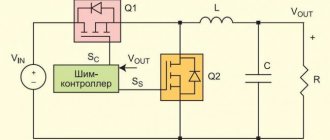
Voltage Regulator Troubleshooting
Remove and disconnect the wires from the part. We inspect the condition of the brushes. They should not have significant defects or chips. In the guide channels of the brush holder, the generator brushes must move freely. If they protrude beyond the edge by less than 5 mm, the generator regulator should be changed.
The test is carried out using batteries and a 12-volt light bulb. The voltage of the second power source must be at least 15 V, so we connect the batteries in series to the car battery and adjust the value to the desired value. We attach the plus from the 1st power source to the output contact, and the minus to ground.
The light bulb is installed between the brushes. When connecting a 16 V source, it should not light up. With a weaker battery, it lights up. If proper combustion is not observed, the regulator should be replaced.
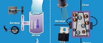
Capacitor device
The simplest capacitor consists of two metal plates (plates) separated by a dielectric layer. Capacitance (the ability to accumulate electrical charge) increases with increasing plate area and decreasing thickness of the insulating layer.
The parameters of the simplest design are too small. There are two ways to increase it:
- An increase in the area of the plates, which leads to an increase in dimensions.
- Reducing the thickness of the dielectric, leading to a decrease in the rated operating voltage due to electrical breakdown.
In order to avoid these problems, special designs have been developed. For example, if you make plates of small width and long length, they can be rolled together with a flexible dielectric into a dense cylinder, resulting in a cylindrical capacitor. By placing the dielectric plates alternately, in the form of a layer cake, and alternating connections to the terminals, a rectangular component with a large effective plate area is obtained.
Different types of construction
Another way is to use a thin oxide layer on the surface of a metal foil as a dielectric and a conducting electrolyte solution as a second plate. This produces an electrolytic capacitor whose design has the largest capacity.
Important! Such devices have the disadvantage of maintaining the polarity of the connection, which limits their use: it is only possible in DC circuits as smoothing filters.
AC circuit
In an AC circuit, a capacitor is a resistance. It quickly accumulates a certain charge and gradually releases it. Accumulation and full release occurs during a change in the electric wave.
DC circuit
In a DC circuit, charge accumulates on the plates, increasing the potential difference across the plates. The potential difference increases to the voltage value. As soon as it becomes equal to the voltage, the common circuit is broken.
Types of capacitors
To start powerful compressor engines, oil-filled non-polar capacitors are used.
The housing is filled with oil inside for good heat transfer to the surface of the housing. The body is usually metal or aluminum. The most affordable capacitors of this type are CBB65.
To start less powerful loads, such as fan motors, dry capacitors are used, the housing of which is usually plastic.
The most common capacitors of this type are CBB60, CBB61.
The terminals are double or quadruple for ease of connection.
Diagnostics of non-polar devices
When checking with a multimeter, we do not need to measure the capacitance of a non-polar capacitor; it is enough to measure its resistance, it should be infinitely large. In the event of a breakdown, the device will show its insignificant value, that is, the part will behave like an ordinary conductor of electric current.
The sequence of actions during testing is as follows:
- it is necessary to set the maximum measuring range in ohmmeter mode;
- use the probes of the device to touch the terminals of the radio component (given the type of capacitor, there is no need to observe polarity);
Testing non-polar models
- if “1” is displayed on the display, this indicates to us that the measured resistance is more than two megaohms, therefore, the part is working, otherwise the multimeter will show some value, which means a short circuit inside the radio component.
Important point! When taking measurements, you should not hold the probes of the device by non-insulated places, since in this case the readings will be unreliable; you will simply measure the resistance value of your body.
Testing can also be carried out in diode testing mode, in this case, if there is a breakdown, the device will indicate a short circuit with a characteristic sound signal.
What is capacity
If you remove a single electrical conductor infinitely far, eliminating the influence of charged bodies on each other, then the potential of the remote conductor will become proportional to the charge. But conductors of different sizes do not have the same potential.
The SI unit of capacitance for a capacitor is the farad. The proportionality coefficient is denoted by the letter C - this is the capacitance, which is affected by the size and external structure of the conductor. The material and phase state of the electrode substance do not play a role - the charges are distributed on the surface. Therefore, in the international GHS rules, capacity is measured not in farads, but in centimeters.
A solitary sphere with a radius of 9 million km (1400 Earth radii) contains 1 farad. A separate conductive element holds charges in quantities insufficient for technical use. According to technologies of the 21st century. a capacitance of capacitors with units of measurement higher than 1 farad is created.
A structure of at least 2 electrodes and a separating dielectric is capable of accumulating the amount of electricity required for the operation of electronic circuits. In this design, positive and negative particles are mutually attracted and support themselves. The dielectric between the electron-positron pair does not allow annihilation. This state of charge is called bound.
Previously, bulky equipment that was not very accurate was used to measure electrical quantities. Now even a novice radio amateur knows how to measure capacitance with a tester.
Markings on capacitors
Knowledge of the characteristics of electronic devices is required for accurate and safe operation.
Determining the capacitance of a capacitor involves measuring the value with instruments and reading the markings on the case. The indicated values and those obtained during measurements differ. This is caused by imperfect production technologies and operational variations in parameters (wear, temperature influence).
The body indicates the nominal capacity and parameters of permissible deviations. In household devices, devices with a deviation of up to 20% are used. In the space industry, military equipment and automation of dangerous objects, a spread of characteristics of 5-10% is allowed. Work plans do not contain tolerance values.
The rated capacity is coded according to IEC standards - the International Electrotechnical Commission, which unites national standards organizations in 60 countries.
The IEC standard uses the notation:
- 3 digit encoding. 2 signs at the beginning - the number of pF, the third - the number of zeros, 9 at the end - the value is less than 10 pF, 0 at the front - no more than 1 pF. Code 689 - 6.8 pF, 152 - 1500 pF, 333 - 33000 pF or 33 nF, or 0.033 µF. To make it easier to read, the decimal point in the code is replaced by the letter "R". R8=0.8 pF, 2R5 - 2.5 pF.
- 4 digits in marking. The last one is the number of zeros. The first 3 are the value in pF. 3353 - 335000 pF, 335 nF or 0.335 µF.
- Using letters in code. The letter µ is μF, n is nanofarad, p is pF. 34p5 - 34.5 pF, 1µ5 - 1.5 µF.
- Planer ceramic products are coded with the letters AZ in 2 registers and a number indicating the power of 10. K3 - 2400 pF.
- Electrolytic SMD devices are marked in 2 ways: numbers - the rated capacity in pF and next to it or in the 2nd line if there is space - the value of the rated voltage; a letter encoding the voltage and next to it there are 3 numbers, 2 determine the capacity, and the last one - the number of zeros. A205 means 10 V and 2 µF.
- Surface mount products are marked with a code of letters and numbers: CA7 - 10 µF and 16 V.
- Encodings - by body color.
Malfunctions and causes of their occurrence
Regardless of what type of capacitor is paper or high-voltage, it can fail as a result of the following faults:
- reduction in nominal capacity as a result of drying out;
- the leakage current exceeds a certain value;
- increase in active losses in the circuit;
- short circuit of the plates (insulator breakdown);
- loss of contact between the plate and the lead of the part (break).
The malfunctions described above can occur as a result of temperature violations, exceeding the permissible voltage threshold, mechanical damage, etc.
Note that by lowering the operating temperature you can significantly extend the service life of almost any radio element. It is overheating that in most cases becomes the main cause of failure of radio components.
As practice shows, most often a capacitor malfunction is caused by a short circuit of the plates, that is, a breakdown. We will tell you in detail how to make a diagnosis in this case.
Calculation using formulas
Calculation of the nominal capacity of an element is required in 2 cases:
- Electronic equipment designers calculate the parameter when creating circuits.
- In the absence of capacitors of suitable power and capacity, craftsmen use element calculations to select from available parts.
RC circuits are calculated using the value of impedance - complex resistance (Z). Ra - current losses due to heating of circuit participants. Ri and Re — take into account the influence of inductance and capacitance of the elements. At the resistor terminals in the RC circuit, the voltage Uр is inversely proportional to Z.
Thermal resistance increases the potential across the load, and reactive resistance decreases. Operating a capacitor at frequencies above resonant frequencies, when the reactive component of the complex resistance increases, leads to voltage losses. The resonance frequency is inversely proportional to the ability to accumulate charge. From the formula for determining Fр, they calculate what values of C (capacitor capacitance) are required for the operation of the circuit.
To calculate pulse circuits, the circuit time constant is used, which determines the effect of RC on the pulse structure. If the circuit resistance and capacitor charging time are known, the capacitance is calculated using the time constant formula. The truth of the result is influenced by the human factor.
Craftsmen use parallel and series connections of capacitors. The calculation formulas are the reverse of the formulas for resistors. A series connection makes the capacitance smaller in the connection of elements; a parallel circuit adds up the values.
Checking in ohmmeter mode
Before checking the capacitor with a multimeter, it is worth completely discharging the capacitor. To do this, you will need to short-circuit its terminals to some metal object. A total of 4 elements will be checked. The following sequence of actions is as follows:
- Set a specific multimeter mode using the switch in the resistance measurement sector. This mode is also called ohmmeter mode. Using this mode, you can determine the presence of a short circuit or problems with the resistance of the element.
- Check the polar capacitors, the capacitance of which is 5.6 μF and 3.3 μF, respectively. To do this, you must first set the multimeter screen to 2 MOhm, and then attach the device’s probe to each terminal.
- View the result on the multimeter display. Resistance will grow rapidly.
It is worth noting that the readings will jump and float, which will create uncertainty about the correctness of the test being carried out. But this can be explained quite simply. The fact is that the probes begin to instantly charge the capacitor when connected to it, and the element immediately begins to absorb the charge. Thus, the longer the probes are on the capacitor, the more charge it will accumulate and the higher the resistance will become. The speed is directly proportional to the element's capacity.
The remaining two, but this time non-polar, capacitors are checked in exactly the same way. You need to touch the capacitor terminals with the probes and wait for the results on the device screen. The unit will confirm the serviceability of each element.
Difficulties of verification
The process of determining the capacitance of a capacitor directly on the board is complicated by the presence of other circuit components - they distort the readings of the device.
First of all, this applies to elements with low resistance to direct current: fuses, inductors, transformer windings. Determining the capacitance of a capacitor without soldering is possible only in the absence of the mentioned components. Semiconductor devices - diodes and transistors - also have an effect.
When checking a capacitor for breakdown by measuring resistance, the multimeter will display the resistance of the Pn junction instead of infinity (on the display “1”). As a result, the state of the capacitor will remain unknown.
No connector for measuring capacitance
You can ring a polar or non-polar capacitor with a multimeter that does not have a special function in the maximum resistance mode, in which it is charged with direct current.
This testing method is even suitable for elements such as SMD capacitor (surface mount) or film capacitor. Checking a polar element differs only in the need to observe polarity.
- discharge the element by short-circuiting its legs;
- set the maximum resistance measurement limit - up to megaohms, if the device allows;
- connect the black probe of the multimeter to the COM socket - this is zero or, in our case, minus, and the red probe to the socket for measuring voltage and resistance;
- touch the black probe to the minus of the part, and the red probe to the plus;
- observe the instrument readings.
Please note that the electrolytic type is always polar, all others are non-polar.
What happens in this case? The multimeter begins to charge the part with direct current. During charging, its resistance increases.
A rapid increase in resistance readings up to a value of “1” (infinitely large) means that the capacitor is potentially healthy, although in this way it is impossible to determine its actual capacity.
Possible error! During such a check, do not touch the probes or element legs with your fingers. You bypass it with your own body resistance, and the tester will show your own resistance. It is recommended to use alligator probes, if available.
Check Features
The capacitor is checked for serviceability using various methods. The main method is by desoldering it from the circuit. Sometimes you can check the functionality without soldering. But the results of the study will not be accurate - it is influenced by other components. To check the circuit, testers with tiny voltages on the probes are used. Low voltage prevents damage to other components of the board.
Regardless of the features of the models, all electrolytic capacitors have high power. When the test is performed, they are recharged. Its duration is only a few seconds. During the charging process, an increase in the resistance level is observed, with the movement of the tester needle or a change in the digital indicators in the electronic multimeter.
Polar capacitors
These electrolytic conductors are polarized. When connecting to the network, it is necessary to check the correct connection. We connect pluses with pluses, and minuses with minuses. Ignoring this rule leads to an explosion of the electrolyte.
Electrolyte can be solid or liquid. The capacitance of the elements is 0.1–100000 μF. The purpose of the elements is signal alignment and filtering. Marks “-” and “+” are marked on the body. The positive lead is longer. When the polarity is reversed, a breakdown of the dielectric occurs, as a result of which the electrolyte instantly evaporates and the housing ruptures. The dielectric is paper impregnated with electrolyte. Modern buildings are pressed in at the top and cut with a cross.
During an explosion, not the whole thing disintegrates, but only the upper part. Taking into account the specially weakened elements, in the event of a malfunction, swelling of the upper part is visible.
Non-polar capacitors
It is easy to visually distinguish non-polar from polar - it will not have polarity markings on the body. Non-polar ones have a different dielectric material. Consists of ceramics or glass. The self-discharge current is much lower, given the higher dielectric resistance than paper. The higher the resistance of the dielectric partition, the lower the leakage current.
It is not at all necessary to observe polarity when connecting to the circuit. Sometimes such conductors are made very small and included in the circuit in large quantities.
The capacity of the parts is small - from microfarads to picofarads.
Checking the serviceability of the electrolytic capacitor
The inspection begins with a visual inspection of the part. An explosion is a natural phenomenon with increased pressure inside the electrolyte housing if they are damaged. Even with a small explosive power, the harm will be to splash their contents around.
To prevent this, a cross-shaped notch is made at the top of the capacitors, which helps relieve pressure inside the housing. Swelling and rupture of the case already indicates a malfunction of the device.
In other cases, you will need to check the functionality of the capacitor with a multimeter, which will measure the battery resistance. To do this, connect the device to the terminals of the capacitor, observing polarity.
Initially the resistance will be close to 0 due to the sparseness of the device. But when charging the capacitor from a battery, you can observe an increase in the resistance value. When charging is complete, the multimeter will display an infinitely large resistance.
Before checking the capacitor, it will need to be discharged, which can be done by shorting the terminals together. The limit value of the measurement is the maximum possible. The positive output of the part is connected to its red counterpart on the device.
Connect the negative black output to another output. When measuring resistance, monitor the constantly increasing readings of the multimeter. There should be no reductions.
Contacts between outputs must be reliable. The process must not be interrupted. It is prohibited to touch them due to the resistance of the human body, which will interfere with charging and determining the performance of the part.
Test results:
- The readings are 0 and there is no or only slight increase. This means that there is a short circuit between the plates. And if the capacitor is connected to the working circuit, a short circuit will occur.
- A noticeable increase in instrument readings, but without them reaching infinity. This means that there is a leakage current, with a significant decrease in the capacity of the product. The result is ineffective operation of the element without fully fulfilling its functional purpose. The signal will be distorted.
The multimeter voltage is up to 1.5 V, and in working circuits with a capacitor it is much higher. Therefore, if there is a leak in the device and its installation at operating voltage, its complete breakdown is possible.
How to test a capacitor with a multimeter
The industry produces several types of testing equipment for measuring electrical parameters. Digital ones are more convenient for measurements and give accurate readings. Arrow people prefer the visual movement of arrows.
If the conder appears to be absolutely intact, it is impossible to check it without instruments. It is better to carry out the check by desoldering it from the circuit. This way the indicators are read more accurately. Simple parts rarely fail. Dielectrics are often damaged mechanically. The main characteristic during testing is the passage of only alternating current. The constant passes exclusively at the very beginning for a short period of time. The resistance of the part depends on the existing capacitance.
The prerequisite for testing a polar electrolytic capacitor with a multimeter for performance is a capacity of more than 0.25 μF. Step-by-step verification instructions:
- Discharging the element. To do this, its legs are short-circuited with a metal object. A short circuit is characterized by the appearance of a spark and sound.
- The multimeter switch is set to the resistance value.
- Touch the legs of the capacitor with the probes, taking into account the polarity. Red to the positive leg, black to the negative leg. This is only necessary when working with a polarized device.
The capacitor begins to charge when the probes are connected. Resistance rises to its maximum. If the multimeter beeps when the probes are zero, it means a short circuit has occurred. If the value 1 is immediately displayed on the dial, then there is an internal break in the element. Such conductors are considered faulty - a short circuit and a break inside the element cannot be repaired.
If the value 1 appears after some time, the element is considered normal.
Testing a non-polar capacitor is even easier. On the multimeter we set the measurement to megaohms. After touching the probes, we look at the readings. If they turn out to be less than 2 MΩ, the part is faulty. More than that - serviceable. There is no need to observe polarity.
Electrolytic
As the name suggests, electrolytic conductors in an aluminum case are filled with electrolyte between the plates. The dimensions are very different - from millimeters to tens of decimeters. Technical characteristics can exceed those of non-polar ones by 3 orders of magnitude and reach large values - units of mF.
In electrolytic models, an additional defect appears associated with ESR (equivalent series resistance). This indicator is also abbreviated ESR. Such capacitors in high-frequency circuits filter the carrier signal from parasitic signals. But it is possible to suppress EMI by greatly reducing the level and playing the role of a resistor. This leads to overheating of the part structure.
Checking the generator on the car
First of all, you need to see if the alternator belt is intact. If it is not torn, then the belt tension is checked. Then it's time for the battery. Using a tester (multimeter), we measure the voltage at the terminals. It should be around 12−12.7 volts. If everything is fine, start the engine. If the battery is discharged, charge it and start the engine again.
We measure the voltage at the battery terminals. It should be within specified limits, usually from 13.2 to 14.5 volts. But on modern cars these limits may differ. If you have an instruction manual, you can read it. Deviation from the specified values in any direction is a malfunction. These deviations can be of three types:
- Lack of charging current - the generator does not work.
- There is a charging current, but below the minimum value -
- Voltage above the maximum value means the battery is overcharged.
But before that, conduct a visual inspection of all the wires and cables that go from the generator to the battery. There should be no visible damage, breaks or oxidation of the electrical wiring. Be sure to check the terminals on the battery, starter and alternator. They must be clean and dry. Any oxidation, rust or dirt must be cleaned off. Often this helps restore lost contact and the car begins to work as expected. If this does not help, we proceed to a detailed check.
Using a Multimeter
For further inspection, it is better to remove the generator from the car. First of all, remove the relay regulator from the generator and check it. To check the voltage stabilizer, you will need a multimeter and a charger with regulated voltage. It would be better to use a power supply instead of a charger. Voltage adjustment from 0 to 16 volts will be sufficient.
Connect the plus of the power supply to the regulator - usually this is a male plug connection. Hook the minus to the minus, it is usually output to the ear of the relay mount. Connect the red wire of the tester to the positive wire of the power supply, the black wire to the negative wire. Connect two stripped wires to the brushes, one for each. A light bulb is connected to the other pre-stripped ends (it can be removed from the rear lights of the car during testing). The test bench is ready.
Continuity of the relay regulator
Connect the power supply to the network, carefully use the regulator knob to begin raising the voltage.
At the same time, monitor the multimeter readings. The light bulb should not light up at the very beginning, but as the voltage rises it should light up, first at half-incandescence and as the voltage increases, the brightness should increase. When the 14.5 volt mark is reached, the regulator should operate, cutting off the voltage. The light should then go out. It is generally accepted that the stabilizer is working if it cuts off the current at values from 14.2 to 14.8 volts. If this happens at lower or higher values, then the voltage regulator is faulty. The relay is also faulty if there is no current cutoff at all.
If the relay malfunctions, replace it with a new one. If it is working properly, we continue checking.
How to check without desoldering
It is possible to ring the capacitor with a multimeter without desoldering. For such a check, we select a working specimen with similar characteristics and solder it into the circuit parallel to the one being tested. The working device will indicate a problem in the first element. The method is not applicable to high voltage circuits.
You can check a powerful starting capacitor with a multimeter without desoldering for the presence of a spark. The charged conductor is closed with a screwdriver or other tool with an insulated handle. A characteristic sound with a spark will indicate the functionality of the device.
It is not advisable to take measurements without special instruments. It is easy to get an electric shock on high-voltage samples, and the exact values cannot be determined.
First way
The first method is the simplest. The subject is checked by a tester and called with a multimeter. The device is put into resistance testing mode. It is also worth considering polarity. The multimeter probes are connected to the terminals of the capacitor and the resistance is measured. It is worth considering that the obtained value has no practical use, since it may be an indication of another element. In this way, you can check the capacitive part for a short circuit. If the values on the display begin to increase gradually, then the printed part is being charged by the tester and is in good condition.
Second way
The second method requires soldering a capacitor with the same values into the circuit next to the element under test. Soldering must be done in parallel. Both elements are measured on a de-energized board.
Important! Without soldering, you can only test parts that are part of low-voltage circuits. For high-voltage circuits, such testing is prohibited.
Third way
A situation often arises when there are several capacitors on the board, and it is very difficult to determine which one is faulty. Soldering each one is quite labor-intensive; they often fail when heated. In order to check without desoldering, it is necessary to measure the output voltage. It must be the same as indicated on the element body. If there is no voltage, then the part is broken or shorted. If the voltage is less than the optimal value, the element has lost part of its capacity.
Without desoldering, you can determine the faulty element visually. The capacitor may simply burst, have damage on the housing, carbon deposits or swelling.
How to understand that a device needs diagnostics
Various signs indicate a faulty capacitor. Headlights that flash in time with the bass of the car speakers mean that the car's electronic components are not receiving enough voltage. In some cases, the signals begin to become distorted, and individual components of the machine do not work correctly.
The ignition capacitor is responsible for producing a spark that ignites the air-fuel mixture in the engine cylinder. If the spark has a weak red color and appears unevenly, if the car cannot be started normally, it is likely that there are problems with the capacitor.
It is important to avoid problems with the ignition capacitor. They arise for three reasons:
The first two options are especially insidious, since the ignition does not immediately fail. The components continue to function, although the spark may no longer have the required power level. The main signs of a breakdown in such a situation are instability of the engine at idle and problems with starting. Be sure to check the capacitor and replace it if necessary! If this is not done, sparks from the breaker will cause the contacts to burn, which will damage the power unit.
Visual inspection
Sometimes one glance is enough to identify a faulty capacitor on the board. In such cases, there is no point in checking it with any instruments. The capacitor must be replaced if a visual inspection shows the presence of:
- even slight swelling, traces of leaks;
- mechanical damage, dents;
- cracks, chips (relevant for ceramics).
Capacitors that have any of the above characteristics CANNOT be used.
Device with capacitance measurement function
In the settings panel of such models there is a “CX” sector. The measuring range is smaller than that of an LC meter (up to 200 µF), but it is sufficient for the most common elements.
The check is simple:
- the multimeter switch is set in the “CX” sector to the position with a numerical value that is closest to the expected capacitance;
- the capacitor leads are brought to the contact pads in the “CX” sector or they are touched with probes inserted into sockets with the same mark (depending on the model);
- The display will show the capacity.
Test results
Electrolytic capacitors are polarity sensitive. "CX" sockets and pads are marked with "+" and "-" symbols. The negative terminal of the capacitor is indicated by a tick.
Devices without capacitance measurement function
Such models are used in ohmmeter mode.
Procedure:
- the black probe is plugged into the “COM” socket (negative potential), the red one into the “V/Ω” socket (positive potential);
- the switch is set in the “Ω” sector to the 2 MOhm position;
- Observing polarity, touch the terminals with the probes.
In ohmmeter mode, the multimeter supplies voltage to the probes. It charges the capacitor and the resistance of the latter, gradually increasing from minuscule to a value of over 2 MOhm or infinity (indicated by one on the display).
The increase in resistance is most objectively reflected by an analog (arrow) tester. A malfunction is indicated by the behavior of the device when the resistance:
- immediately became infinite: the conclusion was cut off;
- stopped at below 2 MOhm: the capacitor is broken.
Based on the time during which the resistance increases from minimum to maximum, by comparison with known-good capacitors, you can approximately determine the capacitance of the test item.
This method is not suitable for testing capacitors with low capacitance - 20 µF and below. They charge quickly and even with a working element, the resistance almost immediately becomes infinite.
To test for reversible breakdown, the capacitor is connected to a laboratory DC source with a voltage regulator, and a multimeter in ammeter mode is connected in series with it. The voltage is gradually increased to the maximum permissible. If during this process the tester displays a non-zero current strength, then a reversible breakdown has occurred.
Recommendations for testing capacitors
Capacitor parts have one unpleasant property - when soldered after exposure to heat, they are very rarely restored. At the same time, you can qualitatively check the element only by unsoldering it from the circuit. Otherwise, it will be shunted by nearby elements. For this reason, some nuances should be taken into account.
After the tested capacitor is soldered into the circuit, you need to put the device being repaired into operation. This will make it possible to monitor his work. If its performance is restored or it begins to function better, the tested element is replaced with a new one.
A combined multimeter device, especially one equipped with a capacitance testing mode, makes it possible to accurately, quickly, and most importantly reliably test capacitor parts
To shorten the test, not two, but only one of the capacitor terminals are unsoldered. You need to know that this option is not suitable for most electrolytic cells, which is due to the design features of the case.
If the circuit is complex and includes a large number of capacitors, the fault is determined by measuring the voltage across them. If the parameter does not meet the requirements, the suspicious element must be removed and checked.
If faults are detected in the circuit, you need to check the release date of the capacitor. The drying out of the element during 5 years of operation is on average about 65%. It is better to replace such a part, even if it is in working order. Otherwise, it will distort the operation of the circuit.
For new generation multimeters, the maximum for measurement is a capacitance of up to 200 μF. If this value is exceeded, the control device may fail, although it is equipped with a fuse. The latest generation equipment contains SMD electrical capacitors. They are very small in size.
Among capacitors in SMD packages, the most popular is the FK series. They have a maximum capacity of 1500 mF, a maximum operating voltage of 100 V. They have an AEC-Q200 automotive certificate
It is very difficult to unsolder one of the terminals of such an element. Here it is better to raise one pin after unsoldering, isolating it from the rest of the circuit, or disconnect both pins.
You will learn how to check the voltage in an outlet with a multimeter from the following article, which we highly recommend reading.
Determination of capacitor operating voltage
Strictly speaking, if there is no marking on the capacitor and the circuit in which it was installed is not known, then it is IMPOSSIBLE to find out its operating voltage using non-destructive methods.
However, having some experience, you can very roughly estimate the operating voltage based on the dimensions of the capacitor. Naturally, the larger the size of the capacitor and the smaller its capacity, the higher the voltage it is designed for.
Method No. 1: determining operating voltage through breakdown voltage
If there are several identical capacitors and you don’t mind sacrificing one of them, then you can determine the breakdown voltage, which is usually 2-3 times higher than the operating voltage.
The breakdown voltage of a capacitor is measured as follows. The capacitor is connected through a current-limiting resistor to an adjustable voltage source capable of delivering obviously more than the breakdown voltage. The voltage across the capacitor is controlled by a voltmeter.
Then the voltage is gradually increased until breakdown occurs (the moment when the voltage across the capacitor suddenly drops to zero). The operating voltage can be taken to be 2-3 times less than the breakdown voltage. But this is... You can have your own opinion on this matter.
Attention! Be sure to follow all safety precautions! When checking a capacitor for breakdown, it is necessary to use a protected stand, as well as personal eye protection.
The energy of a charged capacitor is enough to cause a small nuclear explosion right on your desktop. And some types of ceramic capacitors, during an electrical breakdown, can shatter into very small but hard fragments that can easily pierce the skin (not to mention the eyes).
Method No. 2: finding the operating voltage of the capacitor through the leakage current
This method of finding out the operating voltage of a capacitor is suitable for aluminum electrolytic capacitors (polar and non-polar). And the majority of such capacitors.
The point is to catch the moment at which its leakage current begins to increase nonlinearly. To do this, we assemble a simple circuit and measure the leakage current at various values of the applied voltage (from 5 volts onwards). The voltage should be increased gradually, in equal portions, recording the readings of the voltmeter and microammeter in the table.
I ended up with a sign like this (my instincts told me that this was a fairly high-voltage capacitor, so I immediately started adding 10V at a time):
| Capacitor voltage, V | Leakage current, µA | Current increase, µA |
| 10 | 1.1 | 1.1 |
| 20 | 2.2 | 1.1 |
| 30 | 3.3 | 1.1 |
| 40 | 4.5 | 1.2 |
| 50 | 5.8 | 1.3 |
| 60 | 7.2 | 1.4 |
| 70 | 8.9 | 1.7 |
| 80 | 11.0 | 2.1 |
| 90 | 13.4 | 2.4 |
| 100 | 16.0 | 2.6 |
As soon as it becomes noticeable that the same increase in voltage each time leads to a disproportionately larger increase in the leakage current, the experiment should be stopped, since we are not faced with the task of bringing the capacitor to an electrical breakdown.
If you build a graph from the obtained values, it will look like this: It can be seen that starting from 50-60 volts, the graph of the leakage current versus voltage acquires a pronounced nonlinearity. And if we take into account the standard range of voltages:
Standard range of rated operating voltages of capacitors, V
| 6.3 | 10 | 16 | 20 | 25 | 32 | 40 | 50 | 63 | 80 | 100 | 125 | 160 | 200 | 250 | 315 | 350 | 400 | 450 | 500 |
We can assume that for a given capacitor the operating voltage is either 50 or 63 V. I agree, the method is quite labor-intensive, but not mentioning it would be a mistake.
Low ESR Capacitors
In our rapidly developing world, electronics are increasingly built on the RF part. Switching power supplies have almost completely triumphed over bulky transformer power supplies. We, radio amateurs, still use homemade power supplies made from transformers that we found in the trash.
But since almost all equipment goes into the HF range, then the developers of radio components do not sleep either. They create capacitors that have low ESR and are called LOW ESR , which means low ESR capacitors. On some they write this right on the body:
A distinctive feature of such capacitors is that they are elongated. Also, according to my observations, they most often have a gold stripe:
Nowadays, miniature polymer aluminum capacitors with low ESR are increasingly used:
Where can you most often see them? Of course, by disassembling your personal computer. You can find them in the power supply, as well as on the computer motherboard.
In the photo below we see a computer motherboard, which is completely covered with capacitors with LOW ESR, some of which I marked in the red rectangle:
Ceramic and SMD-ceramic capacitors have the smallest ESR
Interesting video on the topic:
How to measure capacitor leakage current?
The method for measuring leakage current has already been described a little higher. I would just like to add that Iut is measured either at the maximum operating voltage of the capacitor or at the voltage at which the capacitor is planned to be used.
You can also calculate the leakage current of a capacitor by an indirect method - through the voltage drop across a previously known resistance. When checking polarized capacitors for leakage, it is necessary to observe the polarity of their connection. Otherwise, incorrect results will be obtained.
When measuring the leakage current of electrolytic capacitors after applying voltage, it is very important to wait some time (5-10 minutes) so that all electrochemical processes are completed. This is especially true for capacitors that have been out of service for a long time.
There is a connector for measuring capacitance
The further testing method depends on the functionality of the multimeter itself: whether it has special connectors and a capacitance measurement function (indicated by Cx) or not. If yes, then everything is extremely simple:
- unsolder the part from the board;
- clean the legs from oxides and solder residues;
- set the device to a capacitance measurement mode with a measurement limit close to or equal to the capacitor rating indicated on it;
- install the element into a special paired socket on the multimeter, or touch the legs of the metal plates that replace it.
To check an electrolytic capacitor, it is necessary to observe the polarity - plus to plus, minus to minus. If the device sockets are marked with plus and minus, then this is the only way to install it. If they are not marked, it does not matter.
An electrolytic capacitor is a mini-battery that contains electrolyte and is connected only with correct polarity.
Inspection Precautions
Discharging the capacitor is mandatory. This is especially true for high-voltage parts - they can damage the multimeter or shock a person. Discharge by touching the legs with a metal object or connecting a lamp. The second method makes the discharge process smoother.
During measurement, do not touch the open parts of the probe with your hands - the human body has low resistance and a high leakage rate. In this case, the measurement will be incorrect. The current will follow the path of least resistance and the readings will show a value that has nothing to do with the capacitor.
Measurements on high-voltage capacitors are carried out using rubber gloves and insulated instruments.
A properly functioning electronic component is capable of storing and releasing a certain amount of electricity. Breakdowns during operation are determined not only visually, but also using a multimeter. Testing with a measuring device can clarify the suitability of an element for further use.
Output voltage level measurement
For each individual unit this value will be different. Let's take a closer look at checking a car generator. Set the voltage measurement mode on the multimeter scale. First you need to check the voltage with the engine turned off. To do this, measure the voltage value at the battery terminals. We connect the red probe to the positive terminal, and attach the black one to the minus terminal. A charged, serviceable battery will produce a value of up to 12.8 V. We start the engine. Then we take a measurement. Now this value should be no more than 14.8 V, but no less than 13.5 V. If the voltage level is higher or lower, the generator is faulty.
Basic capacitor malfunctions
Capacitive elements play a large role in the circuit diagram of any device. Their main function is to charge a certain amount of current and pulse discharge into the circuit. The main malfunctions of capacitors include:
- Normal breakdown. A breakdown can be caused by an increase in operating voltage. Repair requires not only replacing the element, but also determining the cause of the high voltage.
- Internal break. If a radio component breaks, it loses its capacity, since both of its outputs become isolated. A break can occur when the device is dropped or the element itself is poorly assembled.
- A leak. This problem is due to the loss of some capacity. The smaller the permissible and optimal capacity, the smaller the charge size.
Repair of household appliances
Failure of capacitors leads to the fact that household appliances cease to function. The testing technique described above will allow you to identify the faulty part. Once it is detected, it is enough to replace the faulty element to restore the functionality of the TV, microwave oven or vacuum cleaner.
Knowing how to test a capacitor with a multimeter, you can check how efficient the starting element in a car generator is or determine whether the distributor is faulty.
Attention! Before you begin repairing any electrical appliances, you must make sure that they are disconnected from the power supply. Handling live devices may result in electric shock.