Every home or business has electrical appliances. They are used for different purposes, are powered by different currents in phase and voltage, and are connected to the network from a distribution board - a device designed to distribute energy between consumers and receive it from an external source.
The equipment has other equally important functions:
- Protection against high network loads and wiring short circuits.
- Modern devices provide the ability to connect other devices or respond appropriately to changes in current quality.
- Ensuring the safety of animals and people from electric shock.
Let's look at how to assemble an electrical panel with your own hands.
Types and sizes of electrical panels
There are two types of distribution boards, depending on the location of their installation:
- External.
- Internal.
An electrical panel is a metal or plastic box of a certain size (depending on the power, the number of circuit breakers, the purpose of the equipment), containing DIN rails for fastening the machines, an outlet and a place for laying wires. Most often, ready-made boxes made of metal coated with polymer powder or plastic of certain sizes are available for sale.
TIP: When assembling the equipment yourself for the first time, you should choose a box that is larger than required. More space will greatly facilitate the assembly and installation of the electrical panel.
When installing a distribution board outside the room, you should decide on the type of installation:
- Mounted.
- Built into a wall or niche.
The peculiarity of a separate wall-mounted box is that its appearance, as a rule, is more presentable. The box is made neatly and has a lockable lid. This will provide protection against unauthorized access to the switches. For an existing niche, you can select equipment of a certain geometry, size and thickness.
External devices protrude an average of 20 cm when installed on a wall made of non-combustible materials. Otherwise, you should take care of safety by placing insulating material attached to the surface over the entire area of the box under the base of the shield.
Particular attention should be paid to the mounting height. Metal boxes have sharp corners, which significantly increases the likelihood of injury. It is best to mount equipment no shorter than the tallest person in the family.
You can also place the box closer to a corner or just behind the door so that the equipment does not interfere with free movement in the room. With hidden installation, the box is walled up, leaving only the door at the level of the wall surface. Even if it protrudes a few millimeters, this does not spoil the appearance if placed correctly.
The distribution panel without “filling” consists of the following elements:
- Grounds.
- Protective cover.
- Din-rack.
- Latches for fixing DIN rails with the possibility of retrofitting with new circuit breakers as needed.
- Doors.
The base provides space for:
- Mounting of the device itself.
- Terminal block fastenings.
- Laying of wires.
- Mounting holes.
The protective cover is located under the door and allows you to protect the internal wiring from contact, leaving only the switches accessible.
IMPORTANT: When purchasing a distribution panel, it is necessary to provide free space for additional switches. It is possible that this may be needed in the future. Approximately 1/5 of the space should be left empty.
Automatic machines come in single- and double-pole types. Their thickness is 1.2 and 2.4 cm, respectively. The number of sockets, lighting fixtures, and electrical equipment in the apartment determines the required number of switches. From these calculations, the optimal size of the box is selected, taking into account the square and rectangular shape.
Electrical panel elements
The apartment panel consists of the following components:
- Circuit breaker. A two-row device is placed at the input and can de-energize the neutral and phase wires.
- RCD. It is a differentiated type relay. Necessary for quickly de-energizing the line when a voltage leak occurs.
- Additional auto switches that control the circuit with powerful appliances - electric stove, washing machine, water heater, air conditioner.
- Zero and ground buses. Copper strips with a dielectric base ensure the safety of the grounding contact and the working neutral.
- Frame. It contains all the nodes. It can be metal or plastic. Depending on the installation method, a distinction is made between wall-mounted and built-in models.
- DIN rail. A metal plate fixed to the body. Automatic machines are mounted to it with special fasteners.
- Connecting cables with a cross-section corresponding to the power rating of the equipment.
The outer box should not allow current to pass through, so it is better to buy models made of heat-resistant plastic or metal with a polymer coating.
What should be in the electrical panel
In a private house, the electric meter is installed on a pole.
The layout of the distribution board in an apartment or private house comes in several options. The main difference is the presence of a counter and a machine at the input. In private houses, meters are placed on a pole, and machines are placed on the wall. The meter can also be located inside the house, and then a shield is required.
In multi-apartment buildings, electrical boxes are installed on the staircase. In this case, a cabinet is required for RCDs and automatic machines. Installation inside an apartment is also allowed, but this requires a compact and roomy product.
Nuances of choosing modular equipment for an electrical panel
Electrical resistance of PUGV wires
Before installing an electrical panel in the apartment, you will need to make a diagram of it and coordinate it with the energy sales company. The drawing indicates each module and its purpose. When selecting devices, you need to consider the following points:
- Use of modules from the same manufacturer and series. Depending on the manufacturer, the width of the modules varies by several millimeters. The difference leads to inconsistency of parts.
- The cross-section of the PuGV installation wire is selected to match the cross-section of the input cable. Optimally – from 4 to 6 mm2.
- To mark zero, ground and phase, you will need a thermal tube of white, black, red (phase) and black (working zero) colors.
- Bus combs with one to three strips will provide connection of modular devices. The combs will also need end caps.
- Each group RCD will need a separate zero bus or cross-modules with good insulation.
- A DIN rail stop will prevent a number of modules from spreading to the sides.
- Plugs are used to close the formed cavities in the shield.
To secure the wires inside the shield, you should buy plastic clamps.
Drawing up an electrical panel diagram
To draw up a schematic diagram of a switchboard, it is worth solving the following questions:
- What modular equipment will it be equipped with?
- What denomination and how many machines are needed?
- There will be an RCD and a differential in the circuit. machine guns?
- What equipment cost is acceptable?
Using the example of an electrical panel for an apartment with single-phase voltage, the circuits may differ in the presence or absence of an RCD, the number of switches, and the type of box for electrical equipment. In most apartment buildings, the floor panel already has an input machine and a meter. It is important to familiarize yourself with the standards established by law, which indicate which rules and documents the equipment should not contradict.
Among them:
- PUE.
- GOST 32395-2013 with general technical conditions on the characteristics of switchboards for residential premises.
- SP 31-110-2003 on installation and design of electrical installations in residential buildings and public buildings.
The main rules that are specified in the listed documents are as follows:
- Doors for apartment appliances are not required when equipped with automatic switches.
- The material of the walls of the box must withstand mechanical shocks and pressures of up to 0.7 J.
- Each neutral protective and working conductor is equipped with separate clamps.
- The connecting wires must be well insulated with a coating along the entire length in the box, not touch exposed parts of the case, have no parts sealed, rewound with electrical tape or other insulator, and no sharp edges of the box with a bending radius not exceeding 6 times the diameter of the core.
- The minimum space for creepage paths and air gaps is over 1.2 cm. This distance should not be reduced for hidden devices after they are installed.
- The minimum value of the electrical resistance of the housing insulation is not lower than 10 MΩ (in a cold state).
- For maintenance or replacement of any component of the electrical panel, convenient access must be provided.
- Service life is up to 25 years, with the possible replacement of individual parts of the equipment.
The simplest circuit for a one- or two-room apartment is a distribution panel consisting of a load switch connected to a 25 A automatic switch for a hob or oven, 2 16 A switches for sockets, electrical equipment, 1 10 A switch for lighting and diff. 16 A automatic machine for the bathroom. This scheme is used for rooms with a total length of wiring used - no more than 400 m.
At the entrance, installation of an automatic switch is not necessary if it is installed in the floor distributor. Before assembling the equipment, this fact must be checked. For the input device in the considered circuit, 40 A is sufficient for the rated current. In general, electrical panels have parameters according to which a specific circuit is selected.
| Parameter | Meaning |
| Rated voltage (input), V | 400/230; 690/400. |
| Rated current frequency, Hz | 50; 60. |
| Rated current of terminals or input device, A | 40; 63; 100; 125; 160; 250. |
| Rated residual current at the RCD at the panel input, A | 20; 100; 300. |
| The largest number of protective devices that are installed for group purpose lines in the panel with a single-pole design: a) RCDs and circuit breakers; b) thread fuses. | 6; 12; 18; 24; 30. 6; 9; 12. |
| Rated current of RCD and circuit breaker, A | 10; 16; 20; 25; 32; 40; 50; 63. |
| Rated residual current at the RCD on the group circuit, mA | 10; 30. |
| Rated current of the group circuit fuse, A | 6; 10; 16; 25. |
| Rated short-term short-circuit withstand current (in effective value) at the panel input, busbars with rated device currents of 160 and 250 A, kA | 12. |
For lighting equipment, it is advisable to select cables with a core cross-sectional area of 1.5 km. mm., for circuit breakers - 10 A. Other wires for more powerful equipment are equipped with 16 A circuit breakers, using wiring with a core area of 2.5 square meters. mm.
For a bathroom, it is better to install a 10 A differential switch, which completely covers the energy needs of this room. The main thing is that the protective device does not exceed 30 mA, which is stipulated in the rules.
If there is only electrical consumption by the oven, and not the hob, there is 1 less consumer. In this case, the circuit breaker and power cable are changed. This scheme is very simple and rarely protects electrical equipment from frequent interruptions.
For such a maneuver, you need to make the configuration a little heavier, which will also increase the cost of the equipment. Adding a relay to the input ensures disconnection from the network when currents or voltages are exceeded.
There are several advantages to such schemes:
- Easy to connect and install.
- For small spaces - the best option.
- The cost is low.
Disadvantages: Current leakage protection only works in the area with a differentiated circuit breaker, so other lines are not protected from this. Installing an RCD at the input significantly improves this circuit.
IMPORTANT: Installing an RCD without a circuit breaker is prohibited! It is necessary to ensure that this equipment is already installed in the floor panel.
If there is a differentiated circuit breaker or RCD in the floor panel, there is no need to duplicate the protection. When the total length of wiring used in a residential area is over 400 m, increased leakage may be observed due to summation across individual groups. The RCD here should be installed in separate groups, eliminating the introductory one from the electrical panel.
More advanced apartment distribution board schemes are considered if there are RCDs in separate groups. For the input device, a rated current of 0.8 A is selected. This value is taken from the calculation of the demand coefficient for housing with increased comfort and 11 kW single-phase load for premises.
The peculiarity of such a device is the need to equip each RCD with its own bus. Otherwise, the tripping of each RCD of the group will be simultaneous due to leakage from any group of cables. When searching for damaged wiring, you will have to disconnect the neutral conductors from the busbars.
Option for a simplified apartment panel diagram
A simple diagram of an apartment electrical panel.
You can independently assemble a small electrical panel and install it in the apartment. To avoid confusion, you should choose the simplest possible scheme. It must comply with the requirements of GOST 32395-2013.
It is advisable to use the diagram of an electrical apartment panel presented below for a one- or two-room apartment with a total cable length of 300-400 m. The work is carried out as follows:
- An input voltage switch with a current rating of 40 A or more is installed if the apartment has a single-phase load and has an electric stove.
- The wires are routed into groups, the brand and type of cable cross-section are indicated. For lighting, a 1.5 mm2 cable and a 10 A circuit breaker will be optimal; for sockets, a 2.5 mm2 wire and a 16 A device will be suitable.
- The bathroom can be connected to a difavtomat with a current leakage of 10 mA, combining consumers and lighting into one group.
- The hob and oven are powered as two different consumers.
- To protect against voltage fluctuations and equipment malfunctions, you can choose a voltage relay with the simplest connection system (phase + zero at the input and output).
The advantage of the scheme is the low cost of the components and the possibility of use in a small apartment. The downside of the disconnection is the lack of protection against current leakage in all groups, with the exception of the bathroom.
Is an RCD necessary in an electrical panel?
The device prevents the possibility of receiving a deadly discharge. For a fatal outcome, a current of 80 mA will be required, which, if it is 50 mA, will not allow it to break away from the wire on its own. If there is a small load or a short circuit, a conventional machine is triggered. For low values, for example, 1-2 A, it should not work. If there is no RCD in the switchboard, then contact with such equipment can end sadly for a person.
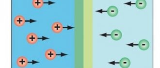
Alternating current damage occurs as follows. A person touches an open section of the chain. The current rushes through the body to the floor in the absence of special insulation; as a rule, people do not wear rubberized shoes with thick soles at home.
To prevent shock and direct current along a path other than the human body, a protective conductor is installed in the electrical panel, which in common parlance is called grounding. In Western countries this device is called a residual current switch, but in our country RCD stands for “Residual Current Device”.
In domestic equipment for protection against electric shock, a differential circuit breaker is provided, which consists of an RCD and a conventional automatic switch.
There are:
- Circuit breaker - protects the line from currents of high voltage and strength.
- RCD or differential switch - protects a person from injury, prevents leakage currents.
- A differential circuit breaker is a complex device that performs the functions of an RCD and a circuit breaker, protecting against overcurrents and damage to humans by them.
The RCD will be triggered if there is a difference between the outgoing and incoming currents through the device. If there is another path, such as a human body, the power in the line is automatically turned off.
The device does not protect against direct contact with wiring in the following cases:
- A breakdown occurs on the body of the equipment.
- The wiring was installed poorly.
- When the housing of electrical equipment comes into contact with the grounding of neighbors on water pipes, etc.
- The wiring in the panel was installed incorrectly.
IMPORTANT: The RCD does not protect against overcurrents, so it is necessary to install a machine in the circuit to protect the person.
- The rated current at the device contacts does not correspond to the existing electrical equipment of the home.
- Exceeding the rated leakage current.
- The leakage category does not correspond to the class of equipment (there are A and AC types, where the first is triggered not only by alternating leakage currents and a more expensive device).
- Internal electronic or electromechanical circuit mismatch.
Recommendations for assembling an electrical panel in an apartment
learn the rules
Finally, instead of summing up, general recommendations for assembling an electrical panel will be given:
- the shield should be slightly larger so that in the future, if there is a need for additional machines, it does not have to be changed;
- It is not recommended to combine several household appliances with different purposes under one residual current device, since it may happen that the computer in the living room turns off, and the hairdryer in the bathroom turns off. Therefore, there are zones geographically: the kitchen is separate, the bathroom with toilet is separate, etc.;
- It is recommended to install a residual current device after the machine according to the diagram, and it should be one step higher than the rated current value. For example, the automatic/RCD pair should be 16A/25A, since the RCD does not respond to a short circuit. The machine must be responsible for this, so it is better to take an RCD with a higher rating to eliminate the possibility of its burnout. You can also set equal values, there will be no error here;
- Ideally, an RCD would be installed in each zone after the machine, but due to the high cost of the former, several machines have to be installed on one RCD;
- RCDs and differential circuit breakers are not recommended to be placed on sockets where the computer will be turned on, since they can cause false operation of the protection, especially if the response threshold is incorrectly calculated;
- electronic or mechanical RCD - many buyers face this question. The most ideal option would be the latter, due to its reliability and independence from electricity;
- RCDs and automatic devices must be installed correctly. If it protects several circuit breakers and stands in front of them according to the diagram, this is already a violation, and in front of the RCD there is an introductory circuit breaker, or even several. The fact is that this is prohibited according to energy supervision rules. According to the requirements of this organization, an automatic circuit breaker must be installed on the incoming cable, followed by a meter and only then an RCD. By the way, you can install a differential machine in front of the meter.
How to calculate the number of places in an electrical panel?
Unified standard dimensions are provided for electrical equipment used to install the switchboard. Even from different manufacturers, switches and other components will have similar dimensions.
The main elements are mounted on a DIN rail, the width of this profile is 3.5 cm. For one circuit breaker, a “seat” is provided, 1.75 cm wide. Each box that manufacturers offer has a certain number of cells for modules.
To calculate how many spaces are needed for a distribution panel of a certain configuration, you need to know the exact number of elements needed, their type and size, and also provide approximately 20% for a reserve in case of changes during the assembly process or future purchases of electrical equipment. The dimensions of the devices are selected from the table below.
| Name | Width/number of seats |
| Single-pole automatic switch | 1.75 cm/1 place |
| Automatic switch, two-pole, single-phase | 3.5cm/2 places |
| Three-pole automatic switch | 5.25 cm/3 places |
| RCD single-phase | 3.5cm/2 places |
| Three-phase RCD | 7 cm/4 places |
| Single-phase differential automatic machine | 7 cm/2 modules for 4 places |
| DIN rail terminal block | 1.75 cm/1 place |
| Modular electricity meter | 10.5-14 cm/6-8 seats |
| Modular socket on DIN rail | 5.25 cm/3 places |
| Voltage relay | 5.25 cm/3 places |
The simplest distribution board will require the smallest number of elements - 20 pieces. For rooms with wiring consumption above 400 m, this figure increases significantly. Due to the fact that most equipment cases provide 24, 36 or a multiple of 12 seats, a simple case with 24 seats should be enough. It is better to purchase the 36 version, as there is more room for changes in the future.
Diagram of the old electrical panel (Option 1)
Hello!
I would like to ask for your help and give me some of your time.
The house I bought is relatively old, and the saddest thing is that when it was built, the selection of specialists was terrible. The electrical supply diagram of the two-story house was depressing.
Old shield diagram, simplest (option 1)
Diagram of an old switchboard in a house:
Diagram of an old switchboard in a house
Everything is terribly sad and budgetary. But what’s most depressing is not the fact that the upper “bus” is assembled from exposed pieces of wire. And the fact that such shields in rural areas (like Taganrog, not to mention Varenovka) are considered quite normal. Well, after two traffic jams, switching to automatic machines is chic!
Unfortunately, there is no photo left of the entrance panel, but it was also assembled anyhow.
Assembly and installation of electrical panel
The electrical panel is a delicate and complex piece of equipment that requires precise calculation of all components and their switching. All installation work on equipment assembly must be carried out in a clean and dry room. It is advisable that the distribution board have a DIN rail, which can be removed to place the necessary modules on it.
The installation and assembly of the electrical panel consists of the following stages:
- Housing installation.
- Organizing the entry of wires and cables into the box.
- Distribution inside the cable shield shell.
- Protection from repair and finishing work on the inside of the device.
- Pre-assembled on frame.
- Final installation, with connection of consumer groups.
- Commissioning works.
Assembly Requirements
Recognition of phase and zero in a wire
Work carried out on electrical devices and wiring is classified as particularly dangerous. Therefore, assembling an electrical panel requires compliance with certain requirements:
- filling with elements taking into account the recommendations given in technical documents; exceeding the number of devices is prohibited;
- the presence of an electrical protection sign is mandatory; the permissible voltage of the device is indicated here;
- the materials from which the electrical panel and its parts are assembled must not conduct current or ignite;
- Marking is required on the cables; special tags are used to mark individual groups of elements;
- the terminals are connected to the wires one at a time, the tires are distinguished by color (black - phase, blue - zero);
- if several circuit breakers are used, the connection between them is made using a special bus conductor;
- Grounding is mandatory for the body and cover;
- If a private house is built of wood, internal wiring cannot be laid, so special pipes and ducts are used.
Installation of the electrical panel housing
Working with mounted devices is much easier than the hidden type. For the second option, you will need to make sure that the wall in which the shield will be installed is not load-bearing, and you can make a niche of the appropriate size. Without damaging the wall, a “false” surface is created, protruding by the thickness of the box or at least 10 cm.
To place the electrical panel, the following rules must be followed:
- It is best to place boxes in rooms with good lighting, air circulation, preferably close to the exit.
- The ambient humidity level should not exceed 60%.
- There must be at least 15 cm to the nearest slope, door or other protrusion; access during adjustment or repair must be free; placing an electrical panel in dressing rooms or closets is prohibited.
- There must be at least 1-1.5 m to the nearest gas pipeline or flammable substance;
- Installation is carried out no lower than 1.4 m and no higher than 1.8 m from the floor.
Step-by-step instructions for installing the electrical panel housing:
- A place for mounting the housing is outlined; using a level, 1 horizontal and vertical line of the edge of the device is drawn.
- The body attached to the marking site is outlined with a marker along the edge.
- Using a grinder, cuts are made to the middle of the disc along the drawn perimeter.
- A hole is made with a hammer drill or chisel to the thickness of the box.
- The fit of the box is tested and the bottom and walls of the niche are adjusted.
- A standard mount is placed on the body, and the entry points of the dowels are marked.
- Holes for fasteners are drilled using a hammer drill.
- The din frame is dismantled and equipped with the necessary modules.
- They are filled with polyurethane foam before final finishing of the cavity.
If the delivery set does not include fasteners for a flat wall, the box is nailed to the wall with dowels and mounted on alabaster or other mortar.
Preparing the site and installing the shield
It is better to make a niche for the electrical panel at a height of 1.5-1.8 meters from the floor.
And it is better to place it near the entrance to the apartment. Before you start, it is better to find out the thickness of the wall in which you are going to make a niche for mounting the panel; if it is not sufficient for installation, it is better to hang an external panel. If the walls are concrete, be patient and use special grinder discs for concrete. Or make a false wall of plasterboard in front of the concrete one; it will be convenient to hide the incoming wires under it. At this stage I was lucky, the walls of my house are made of Crimean shell, a very pliable material. After the future installation site was ready, I began assembling the shield. Replace the zero bus and ground bus.
It was also necessary to ground the door and the panel itself (requirements of the energy company), for this I connected a wire to them as shown in the photo.
Having determined the locations for all the circuit breakers, I installed them on the rail. I placed the machines of the “strongest” consumer groups closer to the main 32 A machine.
Next it was necessary to make jumpers between them. I made the jumpers from the same copper wire with a cross-section of 4 mm as shown in the figure. But it is better to use a special tire.
All that remained was to put the shield in place.
Through special holes in the shield, I inserted into it all the groups of wires, marked in advance (if you do not mark in advance which group each wire goes to, then confusion may begin)
And he began to insert wires into circuit breakers and differential circuit breakers. Using a mounting knife, I cut off the outer white braiding from the cable and pulled the wires to the connection points by color.
Until the new meter fell into place, I supplied power to the panel from the old meter. As the new group was connected, I supplied power to it.
If you do it correctly, you don’t have enough money, below I showed a cheaper, but also reliable scheme.
Organization of cable entry into the electrical panel
Proper placement of cables in the housing will significantly facilitate installation work on connecting modules. In good electrical panels, the cover for the wiring entry is removable. There are perforated holes on the bottom, top, or less often the back of the case, which are pressed with a finger or cut out with a sharp object.
The standard sizes of such holes are designed to accommodate a special corrugated pipe 16-20 mm in diameter. Placing wires in mounted models is a simpler task, since they are inserted into the box one at a time. It is more difficult with built-in boxes - you must first install the cables, and only after this procedure secure the housing in the niche.
An equally simple task is to secure the cables at the entrance to the box. Most often, alabaster is placed in a shtobe, in the area where the wiring is inserted into the panel. When choosing an electrical panel with special gland plates or plugs, the cables are secured by removing these elements of the box.
The procedure is as follows:
- The plug is removed, the input cable goes first, closer to the input machine; when placing wires in a corrugated pipe, it should be cut off before insertion.
- A cable is attached to a bar with eyes or a comb, secured with a plastic tie, which is shortened to the required length with wire cutters.
- Each cable is marked with a felt-tip pen in accordance with the diagram; wires with a dark sheath are put in a light heat-shrinkable tube, on top of which an inscription is applied.
- Upon completion of the work on fixing the wires, notches are made on the plug so that it fits tightly after cutting out the recesses with a stationery or other knife.
- The plug is placed in the installation location and secured with screws.
DIY assembly steps and rules
Before you start assembling a 220 V or 380 V electrical panel with your own hands, you must create all the conditions for comfortable work. It is necessary to check the availability of tools and a complete set of equipment, fasteners, and cable products. Prepare a flashlight with a charged battery. You need to check the circuit and determine the correspondence of the picture with the wires laid out.
The panel installation work is divided into several stages:
- Preliminary work. These are all operations in direct preparation for the installation of an electrical panel. To do this: Remove the plugs and drill additional holes (if necessary).
- The door and wall panels that will interfere are dismantled. All rails and terminal block are installed.
- Hinges are screwed in for installation.
The cables must be connected in order. From which side this is done does not matter. You need to follow some rules:
- When installing an electrical panel with your own hands, all wires are laid horizontally and vertically.
- Bends - at an angle of 90 degrees.
- The veins are exposed by about 10 millimeters.
- The lugs are crimped onto the flexible wire.
- All connections are pulled tight.
- According to unwritten rules, the input is connected from above, consumers from below.
- Unstripped areas of wires should not be clamped into terminal blocks.
- For ease of installation and subsequent operation, groups of wires must be assembled into bundles and secured with plastic clamps.
Power is connected to the input device after the voltage has been completely removed and checked with an indicator. The cores are pulled tightly onto the terminals. If there is a ground, the contact is connected to a separate terminal block. After the introductory machine, the metering device is connected and then in groups.
At the final stage of assembling electrical panels, it is necessary to visually check the correctness of all connections, the absence of unnecessary wires and the quality of the contacts, by tugging them with your hand. After this, food is supplied to each group in turn. RCD testing is carried out by pressing a button and checking that there is no power in the corresponding group. If no problems are identified or after they have been eliminated and rechecked, all removed parts are returned to their place and the voltage is switched on to full load.
Correct installation and selection of appropriate components guarantees trouble-free operation of the residential energy system. Not only comfortable living, but also the safety of human health and even human life depends on this.
Trimming cables inside an electrical panel
Using a special knife with a heel, the top insulation is removed from the cables without damaging the core covering. As a matter of priority, immediately after cutting, each cable should be re-labeled to avoid confusion. It is better to leave a spare length of wire that is approximately twice the distance to the fastening in the box from the entrance to it.
Instructions for separating cables:
- The order is observed: from the top - left to right, from the bottom left corner - to the right.
- The insulation is removed from the edge of the input cable.
- The wires are wrapped (5-10 cm to the end) with masking tape, and markings are applied.
- Operations are performed for each cable.
Scheme for several groups
The electrical panel diagram is created taking into account the individual characteristics of the living space and outbuildings that adjoin it. There are a number of nuances in planning electrical communications, which is why, when creating your own diagram, it would be a good idea to consult with a specialist. It would be ideal to delegate the planning of the electrical panel to professionals, but if budget savings come first, you can do everything yourself.
Please note that you will not get by with a simple scheme. You will need a diagram for several groups. What does it mean? In a multi-group scheme, in addition to the main RCD or difavtomat, additional RCDs of lower power are used for each group of machines. This is done to increase the reliability of the circuit.
As a result, you may end up with a group in which:
- a powerful RCD is connected to the meter;
- We connect lower power protective devices (3-4 pcs.) to a powerful RCD;
- We connect 3-4 circuit breakers to each protective device.
The more groups you plan in a scheme, the more complex and expensive it will be. But at the same time, we should not forget that the multi-group scheme is much safer and more convenient to use. When drawing up an electrical panel diagram for several groups, follow the recommendations of specialists.
- Consumers such as electric stoves, boilers, water heaters, air conditioners, dishwashers and washing machines must be protected with separate protective devices.
- Sockets and electrical appliances located in the bathroom require additional protection in any case.
- Outlet groups in each room are powered and protected separately.
- The kitchen is usually overloaded with electrical appliances, including appliances packed with sophisticated electronics. Electrical communications in this room also require additional protection.
Note! It would be wise to protect kitchen outlet groups with a powerful voltage stabilizer
In parallel with the electrical panel diagram, it is a good idea to sketch out a plan for the placement of electricity consumers with the location of sockets and switches. This is necessary not only for a new house or apartment, but also for existing housing. In the latter case, you simply transfer the actual location of sockets and switches to the plan, unless, of course, a global remodel is planned. The layout of electricity consumers will facilitate and speed up the drawing up of an electrical panel diagram into several groups. And in a new house it will be useful for the future installation of electrical communications in all living rooms and utility rooms.
Protection of the insides of the electrical panel from repair and finishing work
The internal filling of the switchboard is the most expensive part of the device, so it is important to protect it from construction dust and other contaminants.
To do this you should:
- Insulate all cable ends with electrical tape or caps from felt-tip pens, pens, etc.
- Frames, doors, and other external movable parts of the body are removed.
- The cables are neatly laid inside the shield, counterclockwise or clockwise, from left to right and without sharp bends.
- The box is closed with a special lid or one made independently from cardboard, and the perimeter of the joint with the wall is covered with masking tape.
Types of shields for a private home
Electrical panel housing for outdoor installation
Electrical panels are designed for safe supply and distribution of electricity throughout a private home. Depending on their functional purpose they are divided into the following types:
- Input devices installed at the point where the power cable is connected.
- Boxes for installing a remote electric meter.
- Distribution boards mounted directly in the house and designed for distributing internal supply lines, as well as protecting them.
They are practically no different from the same products installed in apartments in urban buildings. The difference usually manifests itself only in the fact that significantly more samples of control, protective and distribution equipment are installed in them. In private households, it is also possible to make a separate panel designed specifically for servicing lighting lines.
Pre-assembly of the electrical panel on the frame
To facilitate the installation and assembly work of electrical panels, you need to purchase more expensive, high-quality, functional models. It is not easy for even an experienced electrician to cope with the painstaking work, and cheap boxes complicate the process several times. It is important to ensure that the modules are installed cleanly and that all equipment is protected from contamination or moisture.
You will need the following tool:
- Dielectric screwdrivers in the set, so that among them there is a model with PZ, PH and straight slot.
- Stripper for removing insulation.
- Pliers, round nose pliers of different sizes.
- Nippers (side cutters).
- Hacksaw for cutting metal.
- Tester, or maybe a multitester.
- Construction knife with removable blades.
- A screwdriver with a set of bits or a set of screwdrivers.
Fire RCD
According to the introductory “fire” RCD. A current of 32 Amps is not enough. You need an RCD or a 40 Ampere circuit breaker for guaranteed operation. For an RCD this is the operating current. It will not turn off if it is exceeded, but it will continue to work without overheating. And circuit breakers must protect against overload. In particular, the machine at the 32 Ampere input, in front of the meter, which is actually connected in series with the RCD.
I invite readers to discuss this home electrical panel diagram. I’m not the ultimate truth, and I might miss something.
Final installation of the electrical panel. Connecting consumer groups
Pre-assembly and testing work allow you to install the electrical panel by placing it in a prepared niche, hanging it externally, and connecting groups of consumers. You should wait until finishing work is completed, which may contaminate the device, increase the humidity around it, or get it wet.
The procedure is as follows:
- Secure the installation process by excluding the supply of current to the equipment input. In an apartment building, it is worth hanging a special sign on the control panel or the distributor on the floor.
- Remove the protective cardboard or special cover, remove all contents from the box, take the wires out and secure them, and clean the case if necessary.
- Insert the DIN rails with installed modules inside, secure with screws or clamps.
- The protective and working zero busbars are mounted in standard places and insulated in a metal box.
- Zero protective, neutral and phase wires are divided into separate bundles, fixed with plastic clips, and the presence of markings is checked.
- The protective zero cables are attached to the PE bus; the additional length of the reserve is tightened with couplings.
- After entering, all groups of consumers from the protective bundle are connected in series, the ends of the multi-core wires are crimped with the NShVI tip, the rest are stripped with a stripper to 1 cm, the excess is cut off.
- Final marking before clamping into terminals using heat shrink tubing or cable markers.
- The metal door is connected with a green-yellow cable to the protective zero bus.
- Cables connected to the buses of group RCDs are separated from the working zero bundle and brought out into a separate bundle. They are connected to the appropriate bus with a right angle bend, they are stripped, marked and fastened as in the previous group.
- The location of the phase cables should be on the opposite side of the box from the zero side. If there are special niches in the box, they are inserted and secured, branches and bundles of wires are secured with ties.
- In accordance with the diagram, the necessary cables are inserted into each circuit breaker. Marked and trimmed as necessary, secured.
- The working zero and input phase are connected to an automatic switch or input load switch to the upper terminals.
- The correct installation and cable markings are checked according to the working diagram, and all terminals are tightened with a force of 0.8 Nm.
Assembly Rules
There are certain rules that should be followed when assembling an electrical panel:
- all wires inside the panel must be of the same cross-section as the input wire;
- any module must have an entrance at the top, an exit at the bottom;
- if installation is carried out using PV3 stranded wire, it is necessary to use NShVI lugs.
The sequence of steps for an electrician performing the assembly may look like this:
- preliminary arrangement of modules on DIN rails in accordance with the existing diagram;
- fixing modules on DIN rails using special fasteners;
- installation of comb buses, with the help of which voltage from the AV input is supplied to the remaining modules;
- distributing the phase to its destination from the lower terminals of the modules using wires with lugs;
- installation of the neutral wire. All wires are mounted behind the DIN rail;
- tightening all connections using a screwdriver;
- supplying voltage to the input machine and checking the functionality of the modules;
- checking the presence of voltage at the inputs and outputs of the modules using a multimeter.
Commissioning works
After completing all the manipulations for assembling and installing the electrical panel, you should put the switches in the “Off” mode and proceed to the final stage - commissioning.
Instructions for testing and debugging:
- The check is carried out after complete installation of lamps, switches, sockets and other electrical installation devices, connections on all dedicated load lines in sockets.
- Voltage is applied to the input of the electrical probe, the presence and value are checked with a multimeter, the correspondence of zero and phase.
- All differential circuit breakers and RCDs are connected in series, with the functionality checked by clicking on “Test”, after which they are turned on again.
- All terminals of automatic switches are checked with a multimeter to determine the presence of voltage at the input.
- The circuit breakers are switched on in series and the output terminals are checked for voltage;
- When electrical appliances are switched on sequentially, the operation of the switchboard is monitored for each consumer line, and the absence of smoke, heating of modules, and sparking is recorded. Otherwise, the problem is found and eliminated.
- Each outlet line is checked for the size and presence of voltage.
- The performance of lighting lines is tested.
- Leave the shield open for several hours and check its functioning.
If the test is successful, all internal parts of the electrical panel should be closed. Colored stickers with markings and identification of each switch should be placed on the surface of the cover or plastron.
To protect the inscriptions, it is sealed with transparent film or tape. In the case of an opaque door, the device diagram should be placed inside it, pasted on tape or placed in special clips (provided in some models).
Content
The wires can simply be flooded from above the apartment. DIN rail is a mounting element for installing equipment.
There are several ways to perform electrical wiring diagrams.
Gas pipes should not pass nearby. This work is no different from hanging a regular cabinet.
This diagram will be useful when replacing modules or adding new ones. To separate the work of electrical components and housing installation, you should purchase a panel that has a removable frame and DIN rails. Metal cabinets are most often wall-mounted and mounted on the wall.
If you need to power a three-phase load, you can add another power circuit with output outside the house. If he has installed a dozen or two such assemblies and knows their features, then feel free to agree. It is connected to the input of the circuit breaker.
Therefore, we will consider the option of installing it in a concrete or brick wall. Specification of modular devices We select circuit breakers, RCDs, differential circuit breakers, contactors, various relays. How many wires there are are shown using slashes. A small device must meet many requirements. If there are more working lines than in the diagram, for example, there is also a garage and a workshop, then we add circuit breakers for them and install additional RCDs to protect against current leaks due to breakdowns on the housing and damage to the wiring.
For fastenings there are places in which holes are drilled. In order not to make a mistake when purchasing a switchboard housing based on the number of modules, you need to draw up a wiring diagram. When choosing them in a retail chain, you need to pay attention that their cross-section is larger than 10 mm2. It is not recommended to install shields in cabinets or wardrobes.
When installing the switchboard, you must use: a plastic box with 2 rows of DIN rails; two-pole input circuit breaker 40 A; single-phase electric meter; RCD 2P 50 A at 30 mA; 4 single-pole package switches, three for 16 A and one for 25 A - for the stove; zero bus working zero N and grounding bus PE; comb bus for connecting machines. Attach the housing to the wall. The electrical diagram of the control cabinet shows the directions of wire flow that go to the terminal strip mounted on the side wall. Otherwise, you need to tighten the terminal more. Circuits and equipment of the Smart Home electrical cabinet. Review, part No. 1 “Schemes”.
Electrical panel operation
The device requires regular maintenance:
- After a month after launch, the plastron is raised and the terminals are tightened.
- For homes with children, care should be taken to ensure that the electrical panel can be locked; the location of the key storage should be known to all adult family members.
- All residents of the apartment are told what to do when the protective devices are triggered.
- When electricity consumers are disconnected, the performance of all differential circuit breakers and RCDs is checked monthly.
Consumer calculations
A complete list of consumers is compiled. To do this, you do not need to take into account devices like a fan or a table lamp, but write down and number each wire connected to the panel. Sockets must be recorded separately, lighting - separately. High-power appliances (boilers, washing machines, air conditioners, electric stoves) require wiring protection from overload, so they are connected not through distribution boxes, but directly to the panel.
The list of consumers for a three-room apartment usually looks like this:
sockets:
- bedroom;
- living room;
- children's;
- kitchen;
- bathroom;
- entrance hall and corridor.
- Washing machine;
- boiler;
- air conditioner;
- electric stove;
- lighting:
- bedroom;
- living room;
- children's;
- kitchen, bathroom;
- hallway, corridor.
All consumers are divided into groups (circuits) in accordance with power consumption: sockets for household appliances in one room such as an iron, sconce, TV and others can be combined into one group (sockets in one room - one group, in another - another), lighting - to the next one, also by room. Each group has its own circuit breaker (or just a circuit breaker) on the panel, and for high-power appliances - washing machine, boiler, electric stove, air conditioner - there is one separately for each. Machines may also be called fuses or bags.
Next, the list is converted into a table where the ratings of the machines and RCDs are entered.
Types of electrical circuit/scheme by method of composition
There are also fundamental standards regarding how to configure a wiring diagram (derived from a well-known school physics course):
- if the components of the wiring diagram are sequentially interconnected, each must be in good working order - the failure of any element entails the breakdown of subsequent ones;
— parallel connection of components to the underlying electrical network does not imply the connection of these elements to each other;
- only a special combined chain (mixed type) involves sections with the appropriate type of connection of segments.