During the transition of the mechanism from a static state to an active state, the rated voltage, which has a standard frequency, begins to flow to the motor windings. This is when the asynchronous machine can consume the greatest amount of energy.
The starting torque of a motor refers to the moment of its rotation while the rotor remains static and the frequency and voltage of the alternating current remain nominal. PM of an electric motor is the process of developing increased torque. To identify the starting torque indicator, there is a formula that involves using the pm multiplicity. This value is indicated in the device passport. To determine the value of the asynchronous PM, you need to apply the formula:
It is better to avoid elevated numbers on the starting current indicators when starting the engine, as this may contribute to a lack of energy required for the correct operation of all other systems and mechanisms. To minimize the value of the starting current, it is rational to use PM of the star and delta type. Such circuits are most common when connecting electric motors. The starting torque of an AED with a wound rotor is determined by the active resistance of the adjustable resistors that are connected to the rotor circuit. In asynchronous machines with a squirrel-cage rotor, the starting torque is characterized by the highest indicator. But at the same time, the starting current indicator is significantly reduced. The electric motor is checked for starting torque, taking into account the dynamic load from the flywheel masses of the structure and the additional torque that is created using friction force. Squirrel-cage asynchronous motors with increased PM have a special rotor design. These properties are typical for engines with double-cage and deep-slot rotors. When the voltage decreases by 2 times, the starting torque of the AED also decreases. This is suitable for structures where startup can be done with minimal load.
What is considered a starting moment?
Many people wonder how to understand the multiplicity of the starting torque of an AED. There is nothing complicated here, since the information is indicated in the certificate, passport or other accompanying document for the electronic motor. Starting torque refers to a torque that is initiated mechanically. It is developed by the motor on the shaft directly at startup, exactly at the time when the current passes through the motor. In other words, PM is the torque that appears on the shaft when the current has a stable value and the rotation speed is zero, and the electric motor windings have a nominal frequency and voltage value.
Increasing motor speed
Increasing the speed of the electric motor also leads to an increase in its power. When choosing a method to increase speed, take into account the type of unit, the features of the model and its scope.
To increase the rotation speed of the commutator motor, either reduce the load on the shaft or increase the supply voltage. Please pay attention to the following nuances:
The above method is also suitable for electric motors with electronically controlled windings (they use feedback), since their properties are very similar to commutator models (the main difference is the impossibility of reversing by reversing the polarity). All of the above restrictions must be observed when working with engines of this type.
Calculation of starting torque
It is determined by a certain formula. The magnitude of the multiplicity can vary from 1.5 to 6. It is important to follow the rule according to which the static torque should always be less than the starting torque. Without this, it is impossible to achieve correct operation of the motor. To understand how the PM multiplicity of an asynchronous device is determined, you need to understand the very mechanism of operation of the device. Directly when starting, the electric motor will consume starting current, its indicator is significantly higher than that of the working one. It is the value that denotes the difference between the indicated currents that is designated as a multiplicity; it is usually taken into account as a coefficient. But rated and operating currents are different designations that should not be confused. The current multiplicity is determined by the motor power. If the power is low, then the starting current is high. How to determine the starting torque of an electric motor and how to determine the starting torque of an asynchronous motor? There is a formula for calculating the starting torque of an AED. You can use the electrical measurement method or use special tables.
Starting currents
Do you want a voltage stabilizer, uninterruptible power supply or generator to operate without failure? Then this article will be useful for you.
One of the main characteristics of household appliances is the electrical power output. It reflects the ability to power the connected load. To correctly select an AC voltage stabilizer, UPS or generator, you need to know the power of the device. To calculate it, you need to calculate the sum of the electrical power of all devices that can be connected at the same time.
One of the main conditions for long and stable operation of the stabilizer, generator and UPS: the power of the equipment should not exceed their output power capabilities. It is better that the total electrical power of electrical appliances that operate simultaneously is 20% less than the output power of the power supply device. The less the stabilizer or UPS operates under overload, the longer it lasts.
The main difficulty lies in calculating the total power. The passport of any device indicates the power in kW. It seems that everything is simple: you need to add up the power of the devices. But therein lies the main mistake.
Advice
Devices that have electric motors, pumps or compressors in their design, at the moment of startup, place a load on the network that exceeds the nominal value by 2–7 times. This phenomenon is due to the presence of inrush currents.
The same rule applies to devices that include inertial components or elements whose physical properties at the time of startup differ from their normal values during operation. A classic example is the change in resistance of an ordinary incandescent lamp.
The design of such lamps contains a tungsten filament; when turned on, the electrical resistance of the tungsten is less (the filament is cold) than during operation. Resistance increases with increasing temperature, therefore, when the lamp is turned on, its power is much greater than during operation. When an incandescent lamp is turned on, inrush currents are present.
The power of any device is calculated as the product of voltage (in volts) and current (in amperes).
As the current increases, the power increases, which means the load on the stabilizer, generator and power source increases.
The definition of starting currents can be formulated as follows: electrical appliances or their elements that have inertial properties, at the moment of starting, place a greater load on the electrical network or power supply than during operation.
The value of starting currents depends not only on the effort to spin the motor or pump rotor to rated speed, but also on the change in conductor resistance. The lower the resistance, the greater the amount of current that can flow through it. When heated, the resistance decreases and the ability of the conductor to pass large currents decreases.
In addition to torque and electrical resistance, inductive power provides additional electrical power to the device at the moment of starting. When the fluorescent lamp is turned on, the inductive coil has low resistance. There is also power to ignite the discharge, which increases the current.
The influence of inrush currents is especially important for voltage stabilizers and on-line uninterruptible power supplies. Stabilizers operate in one of two operating modes: nominal or limit.
In nominal operating mode, power is maintained, but when the quality of power supply deteriorates in the network, very low or, conversely, very high voltage is observed.
note
In this case, the stabilizer goes into maximum operating mode, its output power is reduced by approximately 30%. If an overload of starting currents occurs, it will turn off and the protection system will work.
If this is repeated frequently, the service life of a high-quality stabilizer will be short (let alone Chinese technology).
With on-line UPS, things are more complicated. If such a device is subjected to a load that exceeds the rated load (and inrush currents have a very high speed, and they pass any protection), the fuses do not have time to operate, and the power source may burn out. This is a non-warranty case and repairs will cost a significant amount.
The only type of UPS that can withstand inrush currents 2-3 times higher than the rated value is line-interactive backup power supply systems.
The maximum starting currents are given by refrigerator compressors (single-chamber - up to 1 kW, double-chamber - up to 1.8 kW), as well as deep-well pumps. Their power during startup exceeds the nominal value by 5–7 times.
The smallest starting factor (equal to 2) is observed for Grundfos pumps with a soft start system.
When choosing power supplies or a voltage stabilizer, you need to take into account the time factor of the influence of inrush currents. When you first turn on the stabilizer or generator, all electrical appliances will start working simultaneously and the total load will be large.
During further work, the consumer must evaluate the likelihood of simultaneously starting devices with high starting currents (for example, a refrigerator, pump and washing machine).
If the stabilizer or UPS has low power, then you should independently control the switching on of equipment with inrush currents.
Conclusions:
- When calculating the total power of electrical equipment, the power of devices with starting currents must be calculated not at nominal value, but taking into account the starting currents (in W or A).
- Inrush currents are provided by equipment whose design includes an electric motor, pump, compressor, filament or inductor.
- The worse the voltage in the main wire (below 150 V or above 250 V), the higher the rating of the stabilizer or UPS should be (about 30% more than the total power of the operating equipment).
Inrush currents can be associated with the start of a bicycle's movement: when it starts to move, it takes a lot of force to spin the wheels, but once the bicycle starts moving, less force is required to maintain speed.
Examples of rated power and starting power of household appliances
The table does not reflect the exact values of electrical appliances; only approximate figures are provided for understanding the algorithm for choosing a voltage stabilizer and UPS.
Source: https://StabMart.ru/articles/puskovye-toki.html
Increasing starting torque
The starting torque can be increased due to the frequency converter. If you change the resistance value of the starting rheostat, you will be able to achieve a higher starting torque. But what happens if you reduce the starting torque voltage by half? He will fall sharply. The change in the primary current is determined by the load of the electric motor. With a heavy load on an asynchronous motor, a decrease in the voltage at its terminals leads to an overload of the motor windings with currents with all the ensuing consequences. On the contrary, the starting torque of an asynchronous motor increases when a rheostat is introduced into the wound rotor. There are rules in accordance with which an asynchronous electric motor must be started. Which starting method increases the starting torque of an asynchronous motor? Connecting the rotor to the rheostat during switching on is suitable for switching on motors with different rotors. If a rheostat is included in the circuit, the resistance level increases. This provides an increase in starting torque. Asynchronous motors with increased starting torque are designed specifically for driving mechanisms characterized by high loads at the time of start-up. But motors with an increased slip rate are used for equipment that has uneven shock load characteristics and a high frequency of starts and reverses. How to increase starting torque? It is necessary to use an AED with a high PM. Its further increase can be made if you use motors with a rotor winding of the double “squirrel cage” type; the groove must be deep. Such an AED will have a pair of short-circuited windings on the rotor. One of them is starting, and the other is working. To increase the PM, the starting winding must have greater active resistance than the working one.
Starting an asynchronous motor
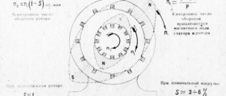
Starting properties of engines .
When starting, the engine rotor, overcoming the load torque and moment of inertia, accelerates from rotation speed n = 0 to n . In this case, the slip changes from s p = 1 to s . When starting, two basic requirements must be met: the torque must exceed the moment of resistance ( Mvr>Ms ) and the starting current I p must be as small as possible.
Depending on the design of the rotor (short-circuit or phase), motor power, and the nature of the load, various starting methods are possible: direct starting, starting using additional resistances, starting at reduced voltage, etc. Below, various starting methods are discussed in more detail.
Direct start.
Starting a motor by directly connecting the stator winding to mains voltage is called direct starting. The direct start circuit is shown in Fig. 3.22. When the switch is turned on at the first moment, slip s = l , and the reduced current in the rotor and the stator current equal to it
, (3.37)
are maximum (see paragraph 3.19 at s=1). As the rotor accelerates, the slip decreases and therefore at the end of the start the current is significantly less than at the first moment. In serial motors with direct starting, the multiplicity of the starting current is kI = IP / I1NOM = ( 5,..., 7), with a larger value referring to motors of higher power.
Rice. 3.22
The starting torque value is found from (3.23) at s = 1:
,(3.38)
From Fig. 3.18 it can be seen that the starting torque is close to the nominal and significantly less than the critical one. For serial engines, the starting torque multiplicity is MP/MNOM = (1.0,…,1.8).
The data shown shows that during direct starting, a current surge occurs in the network supplying the motor, which can cause such a significant voltage drop that other motors powered from this network may stop.
On the other hand, due to the small starting torque when starting under load, the engine may not overcome the moment of resistance on the shaft and will not move. Due to these disadvantages, direct starting can only be used for low and medium power motors (up to approximately 50 kW).
Starting engines with improved starting properties.
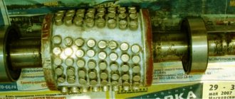
Improving the starting properties of asynchronous motors is achieved by using the effect of current displacement in the rotor due to the special design of the squirrel cage. The effect of current displacement is as follows: the flux linkage and inductive reactance X2 of the conductors in the rotor slot are higher, the closer to the bottom of the slot they are located (Fig. 3.23). Also X2 is directly proportional to the frequency of the rotor current.
Consequently, when starting the engine, when s = 1 and f2 = f1 = 50 Hz, inductive reactance X2 = max and under the influence of this, the current is forced into the outer layer of the groove. The current density j along the h coordinate is distributed along the curve shown in Fig. 3.24. As a result, the current mainly passes through the outer section of the conductor, i.e. over a significantly smaller cross-section of the rod, and, consequently, the active resistance of the rotor winding R2 is much greater than during normal operation. Due to this, the starting current decreases and the starting torque of the MP increases (see (3.37), (3.38)).
As the engine accelerates, the slip and frequency of the rotor current drops and by the end of the start reaches 1 - 4 Hz. At this frequency, the inductive reactance is small and the current is distributed evenly over the entire cross-section of the conductor. With a strongly pronounced current displacement effect, direct starting becomes possible with lower current surges and higher starting torques.
Engines with improved starting properties include engines with deep slot rotors, double squirrel cage rotors, and some others.
Fig.3.23 Fig. 3.24
Motors with deep slots.
As shown in Fig. 3.25, the rotor groove is made in the form of a narrow slot, the depth of which is approximately 10 times greater than its width. The winding in the form of narrow copper strips is placed in these slot-slots. The magnetic flux distribution shows that the inductance and inductive reactance at the bottom of the conductor are significantly greater than at the top.
Fig.3.25
Therefore, when starting, the current is forced into the upper part of the rod and the active resistance increases significantly. As the engine accelerates, the slip decreases, and the current density across the cross section becomes almost the same.
In order to increase the effect of current displacement, deep grooves are made not only in the form of a slot, but also in a trapezoidal shape. In this case, the depth of the groove is slightly less than with a rectangular shape.
Double cage engines.
In such motors, the rotor windings are made in the form of two cages (Fig. 3.26): in the outer slots 1 there is a winding made of brass conductors, in the inner slots 2 there is a winding made of copper conductors.
Fig.3.26
Thus, the outer winding has a higher active resistance than the inner one. When starting, the outer winding is coupled to a very weak magnetic flux, and the inner winding is coupled to a relatively strong field. As a result, the current is forced into the outer cell, and there is almost no current in the inner cell.
As the engine accelerates, the current from the outer cage passes into the inner cage and, at s = sNOM, flows mainly through the inner cage. The current in the outer cage is relatively small.
The resulting starting torque, which is the sum of the torques from the two cages, is significantly greater than that of motors of normal design, and somewhat greater than that of motors with a deep slot. However, it should be kept in mind that the cost of motors with a double cage rotor is higher.
Start by switching the stator winding.
If during normal operation of the engine the stator phases are connected in a triangle, then, as shown in Fig. 3.27, during startup they are initially connected in a star.
Fig.3.27
To do this, switch Q is first turned on, and then switch S is placed in the lower Start position. In this position, the ends of the phases X, Y, Z are connected to each other, i.e. the phases are connected in a star. In this case, the phase voltage is √3 times less than linear.
As a result, the line current at start-up is 3 times less than with a delta connection. When the rotor accelerates at the end of the start, switch S is moved to the upper position and, as can be seen from Fig. 3.27, the stator phases are reconnected into a triangle.
The disadvantage of this method is that the starting torque is also reduced by 3 times, since the torque is proportional to the square of the phase voltage, which is √3 times less when the phases are connected by a star. Therefore, this method is applicable for small load torques and only for motors that operate normally when the stator windings are connected in a triangle.
Start when additional resistors are connected to the stator circuit (Fig. 3.28)
Fig.3.28
Before starting, the switch (starter) is in the open state and switch Q1 is closed.
In this case, additional resistors RDOB are included in the stator circuit. As a result, the stator winding is supplied with a reduced voltage U1n = U1NOM – InRDOB. After the engine accelerates, switch Q2 closes and the stator winding is switched on to the rated voltage U1NOM. By selecting RDOB you can limit the starting current to the permissible one.
It should be borne in mind that the starting torque, proportional to U21P, will be less and is (U1P / U1NOM)2 nominal. It is important to note that with this starting method, losses in resistance RDOB (RDOBI21n) are significant. Instead of resistors RDOB, it is possible to include coils with inductive reactance HDOB close to RDOB.
The use of coils makes it possible to reduce losses in starting resistance.
Autotransformer starting.
In addition to these methods, you can use the so-called autotransformer starting.
The corresponding diagram is shown in Fig. 3.29.
Fig.3.29
Before starting, switch S is set to position 1, and then the autotransformer is turned on and the stator is supplied with reduced voltage U1P. The engine accelerates at reduced voltage and at the end of acceleration, switch S is moved to position 2 and the stator is supplied with rated voltage U1nom.
If the transformation ratio of the step-down transformer is n , then the current I at its input will be n times less. In addition, the starting current will also be n times less, i.e. the current when starting in the network will be n2 times less than when starting directly.
This method, although better than those discussed in paragraph 3.14.7, is much more expensive.
Starting a motor with a wound rotor.
Starting a wound-rotor motor is carried out by connecting a starting rheostat to the rotor circuit, as shown in Fig. 3.30.
The beginnings of the phases of the rotor windings are connected to slip rings and connected through brushes to a starting rheostat with resistance Rp.
The starting rheostat resistance Rp is calculated so that the starting torque is maximum, i.e. equal to critical. Since at start-up the slip is sП = 1, then sП = 1 = sК, the equality MP = M Pmax = MK will be ensured. Then
.
The engine starts according to the curve shown in Fig. 3.31. At the moment of start-up, the operating point on the mechanical characteristic is in position a , and when the engine accelerates, it moves along curve 1, corresponding to a fully turned on rheostat.
At the moment corresponding to point e, the first stage of the rheostat is turned on and the moment increases abruptly to point b - the engine operating point moves to curve 2; at the moment of time corresponding to point d, the second stage of the rheostat is turned off, the operating point jumps to point c and the engine reaches natural characteristic 3 and then to point f. The rheostat is short-circuited, the rotor winding is short-circuited, and the brushes are retracted from the rings.
Thus, the wound rotor makes it possible to run high-power asynchronous motors with limited starting current. However, this starting method is associated with significant losses in the starting rheostat.
In addition, a wound-rotor motor is more expensive than a squirrel-cage motor. Therefore, a wound-rotor motor is used only for high power and high drive requirements.
Calculation of the starting torque of a single-phase motor with the winding on and off
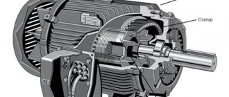
The PM for the rotor of a single-phase motor corresponds to zero, because one winding creates two magnetic fields of equal amplitude only opposite in direction, and the sum of their vectors will be equal to 0. The starting torque of a single-phase motor is the torque that develops on the shaft of the motor when the rotor is static, and The current stator is fixed to the windings. The key elements of each asynchronous machine can rightfully be considered a rotor (rotating element) and a stator (fixed part). The stator provides a magnetic field to rotate the rotor. The PM of a single-phase AEM without a starting winding corresponds to 1/2 of the maximum torque.
How to increase the power of an electric motor at home
So, to carry out the work you should “arm yourself”:
First you need to connect the electric motor to your existing current source and variable EMF and increase its value. The voltage in the windings should increase accordingly and become equal to the value of the EMF (if we do not take into account the losses in the supply conductors, but they are insignificant).
To calculate the increase in engine power, determine the value of the voltage increase and square this figure. For example, if the voltage on the windings doubled (from 110V to 220V), the engine power quadrupled.
Sometimes the most rational way to increase the power of an electric motor is to rewind the winding. In many models this is a copper conductor. You should take a wire of the same material and the same length, but with a larger cross-section. The motor power (and the current in the wire) will increase by the same amount as the winding resistance will decrease. Make sure that the voltage on the windings remains constant.
The calculation in this case is also quite simple. Divide the larger wire size number by the smaller number. If a wire with a cross-section of 0.5 mm is replaced by a wire with a cross-section of 0.75 mm, the power indicator increases by 1.5 times.
If you connect an asynchronous three-phase motor to a single-phase household network, a phase is supplied to the first winding, the phase is shifted to the second by a capacitor, and there is no phase shift to the third. It is the last winding that creates a torque in the opposite direction (braking torque). In this case, the useful power of the engine can be increased by disconnecting the third winding. This will lead to the disappearance of the braking torque generated by the operation of all windings, and, accordingly, an increase in power. This method is convenient when one winding of the motor has already burned out - the remaining two are enough for you to connect and ensure the operation of the unit.
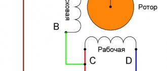
How to determine the starting winding of a single-phase motor?
Depending on the number of terminals of the electric motor terminal box, two structurally different cases are possible:
- for four terminals: the lower active resistance of the ends of the windings after measurement will indicate the working (main) winding, the larger one will indicate the starting (auxiliary) winding;
- for three terminals, three measurements are taken of the ends of the windings: the lower resistance will indicate the main winding, the average value will indicate the starting winding, and the larger one will be the sum of the active resistances of the main and starting windings.
To invert the direction of rotation of a single-phase motor, the ends of the windings of any of the stator phases should be swapped.
Write comments, additions to the article, maybe I missed something. Take a look at the site map, I will be glad if you find anything else useful on my site. All the best.
Expert opinion
It-Technology, Electrical power and electronics specialist
Ask questions to the “Specialist for modernization of energy generation systems”
Basic connection diagrams Further rotation of the rotor is ensured by the pulsating magnetic field of the working phase, as already described in the previous paragraph. Ask, I'm in touch!
What methods of controlling electric motors are used in practice?
Controlling an electric motor implies the ability to change its speed and power. So, if a voltage of a given magnitude and frequency is applied to an asynchronous motor, it will rotate at the rated speed and will be able to provide power on the shaft no more than the nominal value. If you need to lower or increase the speed of the electric motor, frequency converters are used. The inverter can provide the required acceleration and deceleration modes, and will also allow you to quickly control the operating frequency.
To ensure the required acceleration and deceleration without changing the operating frequency, a soft start device (SPD) is used. If you only need to control engine acceleration, use a star-delta connection circuit.
To start motors without inverters and soft starters, contactors are widely used, which allow remote control of start, stop and reverse.
Source