Dependence of frequency on the number of pole pairs
When considering the issue of obtaining alternating current, it is indicated that for one revolution of the rotor, the electromotive force (EMF) induced in the conductors of the generator winding had one period. If the generator rotor makes, for example, 5 rpm, then the EMF will have 5 rpm or the generator current frequency will be equal to 5 Hz. Consequently, the number of revolutions per second of the generator rotor is numerically equal to the current frequency.
The current frequency f is expressed by the following relation:
where n is the number of rotor revolutions per minute.
To obtain a standard current frequency of 50 Hz from the generator, the rotor must make 3000 rpm, that is
However, our reasoning was valid only for a two-pole generator, that is, for a machine with one pair of poles p.
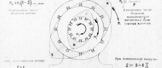
If the machine is four-pole, that is, the number of pairs of poles is equal to two: p = 2 (Figure 1), then one full period of current change will take place per half-turn of the rotor (1 - 5 positions of the conductor in the drawing). During the second half-turn of the rotor, the current will have one more period. Consequently, during one revolution of the rotor of a four-pole machine, the current in the conductor has two periods. In a six-pole machine (p = 3), the current in the conductor will have three periods per revolution of the rotor.
Figure 1. Variation of alternating current in the rotor conductor of a four-pole generator
Thus, for machines with p pairs of poles, the current frequency at
rpm will be p times greater than for a two-pole machine, that is
Hence the formula for the dependence of rotation speed on frequency and number of pole pairs will have the following form:
Example 1. Determine the frequency of the alternating current received from a generator with eight poles (p = 4), the rotor speed of which is n = 750 rpm. Substituting the values of p and n into the formula for determining the frequency of the current, we obtain:
Example 2. Determine the rotation speed of the rotor of a twenty-pole generator (p = 10), if the frequency meter showed the current frequency f = 25 Hz. Substituting the values of p and f into the formula for determining the number of rotor revolutions n, we obtain:
Example 3. The rotor speed of an asynchronous motor is 250 rpm. Determine the number of pole pairs of an asynchronous motor if the frequency of the supply network is 50 Hz:
Therefore, the motor has 24 poles.
Source: Kuznetsov M.I., “Fundamentals of Electrical Engineering” - 9th edition, revised - Moscow: Higher School, 1964 - 560 p.
www.electromechanics.ru
Methods for determining the characteristics of an electric motor
To determine which of these groups the engine belongs to, you do not need to disassemble it, as some experts advise, in order to secure a work order. The fact is that disassembly of an electric motor can only be carried out by a sufficiently qualified master. In fact, it is enough to open the protective cover (another name is the bearing shield) and find the winding coil. There may be several such coils, but one is enough. If a coupling half or pulley is attached to the shaft, you will also need to remove the lower shield.
If the coils are connected using parts that interfere with viewing the information, these parts must not be disconnected under any circumstances. You need to try to determine by eye the ratio of the size of the coil and the stator.
The stator is the stationary part of the electric motor, while the moving part is called the rotor. Depending on the design features, either the coil itself or magnets can act as a rotor.
If the coil covers half of the stator ring, such an engine belongs to the third group, that is, it is capable of delivering up to 3000 revolutions. If the size of the coil is a third of the size of the ring, this is a motor of the second type; accordingly, it is capable of developing 1500 rpm. Finally, if the coil only covers a quarter of the ring, it is type 1. The electric motor develops a power of 1000 rpm.
There is another way to determine the rotation speed of the rotor shaft. To do this, you also need to remove the cover and find the upper part of the winding. The location of the winding sections determines the speed. Typically the outer section occupies 12 slots. If you count the total number of slots and divide by 12, you can get the number of poles. If the number of poles is 2, the motor has a rotation speed of about 3000 rpm. If there are 4 poles, this corresponds to 1500 rpm. If 6, then 1000 rpm. If 8, then 700 rpm.
The third way to determine the number of revolutions is to carefully examine the tag on the engine itself. The number on the marking at the end corresponds to the number of poles. For example, for marking AIR160S6, the last digit 6 indicates how many poles the coil uses.
The easiest way to measure the speed is with a special tachometer. But due to the narrow specialization of application, this method cannot be considered as generally available. Thus, even if no technical documentation has been preserved, there are at least 4 ways to determine the speed of an electric motor.
three-phase asynchronous electric motor | electrician for beginners
slip
The rotation frequencies of the rotor and the electromagnetic field of the stator of a three-phase asynchronous electric motor do not coincide, which is why it is called asynchronous. The difference in lag is called slip and is expressed by the formula s=(nc-nr)/nc, where nc is the stator field rotation frequency, nr is the rotor rotation frequency. The engine tag indicates exactly the number of rotor revolutions. For example, on the tag we read: 960 rpm. This means that the synchronous rotation speed of the stator field is 1000 rpm. The slip value is not constant and depends on the engine load. In practice, you can forget about sliding, but about the rotation frequency in more detail.
synchronous rotation frequency of the stator magnetic field
The rotation speed of the stator magnetic field does not change (synchronous), it is calculated by the formula nc=60f/p, f is the frequency of alternating current (50 Hz), p is the number of pole pairs. A three-phase asynchronous electric motor can be 3000, 1500, 1000, 750 rpm (it can even be 500) - it all depends on the number of pole pairs. Remember the magnet in physics class? It has two poles - north (blue) and south (red). Likewise, the motor winding has two poles: one half of the winding is wound on one side of the stator, the other half is wound on the opposite side. These two halves, which make up a single phase winding, are called a pair of poles. But the winding can be evenly divided along the stator slots not in half, but into 4 parts, then you get 2 pairs of poles, 6 parts - 3 pairs, etc. Please note: Do not confuse the number of pole pairs with the number of poles. The number of poles is the number of parts into which the winding is divided. Based on the formula nc = 60f/p, we see that a three-phase asynchronous electric motor with 4 pairs of poles (the winding is divided into 8 parts) is designed for 750 rpm. (nc=60*50/4=750), and with 2 pairs (the winding is divided into 4 parts) - 1500 rpm. The brand designation of a three-phase asynchronous electric motor indicates the number of parts into which each winding is divided. If you can't read the RPM on the tag, the brand designation will help. For example, the AIR-S100MA6BU3 brand after the designation of overall and installation dimensions 100MA has the number 6. This means that the winding is divided into 6 parts (3 pairs of poles). From here we conclude: the engine is designed for 1000 rpm. Multi-speed electric motors are designated by the number of poles (the number of winding parts) in this way: AIR-S100MA6/4/2BU3, that is, three speeds: 1000 rpm (number 6), 1500 rpm /min. (4) and 3000 rpm. (2). If the synchronous rotation speed of the stator magnetic field is unknown, you will have to open the cover and count the number of poles or measure the rotor rotation speed with a tachometer, taking into account slip.
determination of power and rated current
Often the power and rated current values on the tag are erased. How to determine them? You will have to connect them to the network and measure the phase current with a current clamp. There is no need to connect the load; it is enough to determine the no-load current and calculate the rated current from Table 1. The table shows the no-load current as a percentage of the rated current.
Table 1
Then we apply the power formula for a three-phase asynchronous electric motor P=√3UIcosφη and determine the power using Table 2.
table 2
For example, measuring the no-load current showed 5.5 A. Engine at 1500 rpm. and in size corresponds to power from 1.1 to 5 kW. We determine the rated current based on the fact that the idle speed of these motors is 65% of the rated one: 5.5 A / 0.65 = 8.46 A (remember mathematics: finding a whole number by its percentage part). Next, we turn to the power formula P=√3UIcosφη. We choose cosφ approximately - 0.85, efficiency - 0.85 (Table 2). Р=1.73*380*8.46*0.85*0.85=4018 W. It should be taken into account that we received the power on the shaft, and the active power consumed is calculated using the same formula, but only without efficiency. When determining the total power, cosφ must also be excluded. Since the calculation was approximate, we can assume that the engine is most likely 4 or 4.5 kW. Of course, I made up this example, and therefore the result is made up. The main thing is to understand the algorithm for determining the unknown parameters of a three-phase asynchronous electric motor.
electricku.ru
Electric motors as part of gearmotors
Electric motors have long been included in various gearmotors. They find their application in three-stage MTs3U type. and in two-stage type MTs2U. Electric motors have almost 90% efficiency and do not require constant maintenance. An important parameter is the exceptional environmental friendliness of the electric motor; there are no harmful emissions at all, which makes it indispensable for indoor installation. In short, electric motors are currently recognized as 3 or even 4 times more efficient than traditional internal combustion engines.
But sometimes, in the event of an electric motor failure, the buyer finds out that absolutely no accompanying documentation is attached to it. Marking nameplates, even if they have been preserved, may be in a worn-out, shabby state, so that it is simply impossible to see anything on them. How, then, can you determine the engine power and its speed? Here are some step-by-step tips to help you do this.
It should be borne in mind that the number of revolutions refers to the so-called asynchronous speed. Synchronous speed is the speed of rotation of the magnetic field. Asynchronous speed is slightly lower than synchronous due to the presence of mass in the rotating element, as well as the influence of friction forces, which can significantly reduce the efficiency of the motor. However, in practice these differences are almost never of decisive importance.
There are currently 3 main categories of asynchronous electric motors on the market. The first category of the catalog is motors operating at 1000 rpm. In practice, this number is about 950-970 revolutions, but for clarity, it is still rounded to the nearest thousand. The second category is motors producing 1500 rpm. This is also rounded as the actual range is 1430-1470. The third is 3000 rpm. Although in reality such a motor produces 2900-2970 rotations.
Operating principle of electric motors
The principle of operation of electric motors. Basic concepts.
Magnetism
The most characteristic magnetic phenomenon - the attraction of pieces of iron by a magnet - has been known since ancient times. Another very important feature of magnets is the presence of poles: north (negative) and south (positive). Opposite poles attract, and like poles repel each other.
A magnetic field
The magnetic field can be conventionally represented by lines in the form of a magnetic flux moving from the north pole to the south. In some cases, determining where the north and south poles are is quite difficult.
Electromagnetism
Around a conductor, when an electric current is passed through it, a magnetic field is created. This phenomenon is called electromagnetism. The physical laws are the same for magnetism and electromagnetism.
The magnetic field around conductors can be strengthened by winding them on a coil with a steel core. When a conductor is wound around a coil, all the lines of magnetic flux generated by each turn merge and create a single magnetic field around the coil.
The more turns on the coil, the stronger the magnetic field. This field has the same characteristics as a natural magnetic field, and therefore it also has a north and south pole.
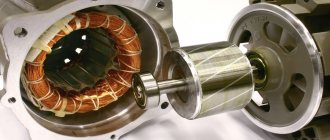
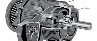
The rotation of the electric motor shaft is caused by the action of a magnetic field. The main parts of an electric motor: stator and rotor.
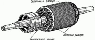
Rotor:
The moving part of an electric motor that rotates with the electric motor shaft, moving along with the magnetic field of the stator.
Stator:
Fixed component of an electric motor. It includes several windings whose polarity changes when alternating current (AC) passes through them. Thus, a combined stator magnetic field is created.
Rotation under the influence of a magnetic field
The advantage of magnetic fields created by current-carrying coils is the ability to swap the poles of a magnet by changing the direction of the current. It is this ability to change poles that is used to convert electrical energy into mechanical energy.
Like poles of magnets repel each other, opposite poles attract. This property can be said to be used to create continuous rotor motion by constantly changing the polarity of the stator. The rotor here is a magnet that can rotate.
Pole rotation using alternating current
Pole rotation using alternating current
The polarity is constantly reversed using alternating current (AC). Next we will see how the rotor is replaced by a magnet, which rotates under the influence of induction. Alternating current plays an important role here, so it will be useful to provide some brief information about it here:
Alternating current - AC
Alternating current is understood as an electric current that periodically changes its direction in a circuit so that the average value of the current over the period is zero. A rotating magnetic field can be created using three-phase power. This means that the stator is connected to a three-phase AC source. A complete cycle is defined as a 360 degree cycle. This means that each phase is located at an angle of 120 degrees relative to the other. The phases are depicted as sinusoidal curves, as shown in the figure.
Three-phase alternating current
Three-phase power is a continuous series of overlapping alternating current (AC) voltages.
Pole reversal
The following pages explain how the rotor and stator interact to make the motor rotate.
For clarity, we replaced the rotor with a rotating magnet and the stator with coils. On the right side of the page is an image of a two-pole three-phase electric motor. The phases are connected in pairs: the 1st phase corresponds to coils A1 and A2, the 2nd phase - B1 and B2, and the 3rd phase corresponds to C1 and C2. When current is applied to the stator coils, one of them becomes the north pole, the other becomes the south pole. Thus, if A1 is the north pole, then A2 is the south pole.
AC Power
The windings of phases A, B and C are located at an angle of 120 degrees relative to each other.
The number of poles of the electric motor is determined by the number of intersections of the winding field with the rotor field. In this case, each winding is crossed twice, which means that we have a two-pole stator. Thus, if each winding appeared four times, it would be a four-pole stator, etc.
When electric current is applied to the phase windings, the motor shaft begins to rotate at a speed determined by the number of poles (the fewer poles, the lower the speed)
Rotor rotation
The following describes the physical principle of operation of an electric motor (how the rotor rotates inside the stator). For clarity, let's replace the rotor with a magnet. All changes in the magnetic field occur very quickly, so we need to break the whole process into stages. When three-phase alternating current passes through the stator windings, a magnetic field is created in it, resulting in mechanical forces that cause the rotor to rotate in the direction of rotation of the magnetic field.
Once it starts rotating, the magnet will follow the changing magnetic field of the stator. The stator field is changed so as to maintain rotation in one direction.
Induction
Previously, we established how an ordinary magnet rotates in a stator. AC motors have rotors rather than magnets. Our model is very similar to a real rotor, except that the rotor is polarized under the influence of a magnetic field. This is caused by magnetic induction, due to which an electric current is induced in the rotor conductors.
Induction
Basically the rotor works the same way as a magnet. When the electric motor is turned on, current flows through the stator winding and creates an electromagnetic field that rotates in a direction perpendicular to the rotor windings. Thus, a current is induced in the rotor windings, which then creates an electromagnetic field around the rotor and rotor polarization.
In the previous section, to make it easier to explain the principle of operation of the rotor, replacing it with a magnet for clarity. Now let's replace the stator with a magnet. Induction is a phenomenon that occurs when a conductor moves in a magnetic field. The relative movement of a conductor in a magnetic field leads to the appearance of a so-called induced electric current in the conductor. This induced current creates a magnetic field around each rotor conductor winding. Since three-phase AC power causes the stator's magnetic field to rotate, the induced magnetic field of the rotor will follow this rotation. This way the motor shaft will rotate. AC motors are often called AC induction motors, or AC induction motors.
Operating principle of electric motors
Induction motors consist of a rotor and a stator.
The currents in the stator windings are created by the phase voltage, which drives the induction motor. These currents create a rotating magnetic field, also called a stator field. The rotating magnetic field of the stator is determined by the currents in the windings and the number of phase windings.
A rotating magnetic field forms a magnetic flux. The rotating magnetic field is proportional to the electric voltage, and the magnetic flux is proportional to the electric current.
The rotating magnetic field of the stator moves faster than the rotor, which promotes the induction of currents in the windings of the rotor conductors, resulting in the formation of a rotor magnetic field. The magnetic fields of the stator and rotor form their own fluxes, these fluxes will attract each other and create a torque that causes the rotor to rotate. The operating principles of an induction motor are shown in the illustrations on the right.
Thus, the rotor and stator are the most important components of an AC induction motor. They are designed using CAD (Computer Aided Design). Next we will talk in more detail about the design of the rotor and stator.
Motor stator
The stator is the stationary electrical component of an electric motor. It includes several windings, the polarity of which constantly changes as alternating current (AC) passes through them. Thus, a combined stator magnetic field is created.
All stators are installed in a frame or housing. The stator housing of Grundfos electric motors for electric motors up to 22 kW is most often made of aluminum, and for electric motors with higher power - from cast iron. The stator itself is installed in the stator housing. It consists of thin plates of electrical steel wrapped in insulated wire. The core consists of hundreds of such plates. When power is applied, alternating current passes through the windings, creating an electromagnetic field perpendicular to the rotor conductors. Alternating current (AC) causes the magnetic field to rotate.
The stator insulation must comply with the requirements of IEC 62114, which provides different protection classes (temperature levels) and temperature change (AT). Grundfos electric motors have protection class F, and when the temperature increases, class B. Grundfos produces 2-pole motors with power up to 11 kW and 4-pole motors with power up to 5.5 kW. Grundfos purchases more powerful electric motors from other companies whose product quality meets Grundfos standards. For pumps, stators with two, four and six poles are mainly used, since the speed of the electric motor shaft determines the pressure and flow of the pump. The stator can be manufactured to handle different voltages, frequencies and output powers, as well as a variable number of poles.
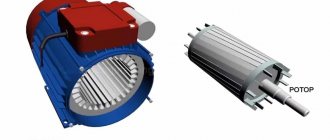
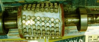
Motor rotor
Electric motors use so-called “squirrel wheels” (squirrel-cage rotors), the design of which resembles squirrel drums.
When the stator rotates, the magnetic field moves perpendicular to the windings of the rotor conductors; current appears. This current circulates through the windings of the conductors and creates magnetic fields around each rotor conductor. Since the magnetic field in the stator is constantly changing, the field in the rotor also changes. This interaction causes the rotor to move. Like the stator, the rotor is made of electrical steel plates. But, unlike the stator, with windings made of copper wire, the rotor windings are made of cast aluminum or silumin, which act as conductors.
Asynchronous electric motors
In previous sections, we discussed why AC motors are also called induction motors, or squirrel wheel motors. Next, we will explain why they are also called asynchronous electric motors. In this case, the relationship between the number of poles and the number of revolutions made by the rotor of the electric motor is taken into account.
The rotation frequency of the magnetic field is generally considered to be the synchronous rotation frequency (Ns). The synchronous speed can be calculated as follows: line frequency (F) multiplied by 120 and divided by the number of poles (P).
If, for example, the mains frequency is 50 Hz, then the synchronous speed for a 2-pole electric motor is 3000 rpm.
The synchronous speed decreases as the number of poles increases. The table below shows the synchronous speed for different numbers of poles.
Synchronous speed for different number of poles
| Number of poles | Synchronous speed 50 Hz | Synchronous speed 60 Hz |
| 2 | 3000 | 3600 |
| 4 | 1500 | 1800 |
| 6 | 1000 | 1200 |
| 8 | 750 | 900 |
| 12 | 500 | 600 |
Motor slip
Now we already know that AC electric motors are called asynchronous because the moving field of the rotor lags behind the field of the stator.
In AC motors, torque results from the interaction between the rotor and the rotating magnetic field of the stator. The magnetic field of the rotor windings will tend to approach the magnetic field of the stator, as described earlier. During operation, the rotor speed is always lower than the speed of the stator magnetic field. Thus, the rotor magnetic field can cross the stator magnetic field and create torque. This difference in the rotational speed of the rotor and stator fields is called slip and is measured in %. Sliding is necessary to create torque. The greater the load, and therefore the torque, the greater the slip.
www.eti.su
Electric motor poles
A DC motor is a device that converts electrical energy into mechanical energy. The operating principle of such an electric motor is based on the rotation of a magnetic field.
Number of motor pole pairs
- The number of pole pairs of an electric motor determines the speed at which the motor shaft will rotate. The calculation is made using special formulas. At the maximum permissible load, the rotation speed may slow down slightly due to slipping. Sliding speed is also calculated using the appropriate formulas.
- To operate a synchronous electric motor, it is necessary to ensure an equal number of poles and working windings. The same applies to an asynchronous electric motor.
- Moreover, a squirrel-cage rotor in an asynchronous electric motor can work perfectly even with a different number of poles of the stator winding.
- The Dolivo-Dobrovolsky asynchronous electric motor has three windings on the stator poles. A rotor is fixed inside the stator. The three poles of the magnetic current can create a corresponding rotation if the windings are connected in a special way and the motor is connected to a three-phase network.
- On the inner ring of the pole, which faces the rotor, the total magnetic flux will be redirected from the pole of the second coil to the pole of the third coil.
- Accordingly, the total magnetic flux can change its direction if you change the direction of the current in the stator winding, or poles. The result is an asynchronous electric motor.
Trust all work to professionals
If you have purchased an electric motor, its installation, maintenance or repair should only be carried out by specialists with the appropriate level of technical training.
You cannot change the winding yourself or replace the flow of guiding energy in the poles. You will automatically lose the manufacturer's warranty and subsequent repairs, possibly major ones, will be carried out at your own expense.
Manufacturers of electric motors offer consumers a huge range of electric motors with different power and shaft rotation speed. From such a variety, you can certainly choose an electric motor that will fully meet your requirements and perform the assigned tasks.
When purchasing an electric motor in you can get advice from the seller on selecting an electric motor with any number of poles by phone.
Date: Sunday, 15 December 2013
www.rosdiler-electro.ru
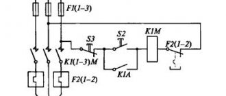
8.7. Controlling the speed of an asynchronous motor by changing the number of pole pairs
This method of speed control can only be implemented using special IMs, called multi-speed. The peculiarity of these IMs is that their stator winding consists of two identical sections (half-windings). Due to different connection schemes, the number of pole pairs can be changed
HELL. According to the formula
this allows you to change the speed of rotation of the magnetic field
and thereby regulate the speed of blood pressure. The rotor of multi-speed IMs is usually squirrel-cage.
Since the number of pairs of IM poles can only take discrete values (
= 1, 2, 3, 4...), then the blood pressure speed can only be adjusted stepwise in this way [1].
Let's consider the principle of obtaining a different number of pole pairs when switching sections of the stator winding using the following example.
Let the phase of the stator winding consist of two identical sections 1n - 1k, 2n - 2k, each having two conductors (Fig. 8.17a) and connected in series and in accordance. A current flows through the stator winding, currently having the direction shown by the arrows. Using the gimlet rule, we determine the direction of the magnetic field lines created by the current I flowing through the conductors. It is not difficult to notice that the magnetic field in this case has four poles or
= 2.
a B C)
Rice. 8.17. Connection diagrams of stator winding sections for changing the number of pole pairs of the IM
Let us now change the connection diagram of the sections by connecting them in series and counter-currently (Fig. 8.17b), leaving the same direction of the current supplied to the winding. In this case, the stator winding forms a magnetic field with half the number of pole pairs. A halving of the number of pole pairs is also achieved in the circuit (Fig. 8.17c), where the sections are connected in parallel.
In this and other cases, reducing the number of pole pairs is achieved by changing the direction of the current to the opposite in one of the sections (in this case, the second). In this case, the range of changes in the speed of rotation of the magnetic field is equal to two.
Most often in practice, two switching schemes for the stator winding of multi-speed IMs are used: from triangle (D) to double star (D) and from star (D) to double star (D).
Let's consider the stator connection diagrams and mechanical characteristics of the IM for these cases.
Triangle is a double star. To obtain more pole pairs
sections of each stator phase are connected in series and in accordance and connected in a triangle (Fig. 8.18a).
And
– the beginning of the first and second sections of the phase, respectively
;
And
– their ends (designations for phase terminals
And
similar). Connecting sections according to the diagram (Fig. 8.18b) is similar to the diagram (Fig. 8.17c) and will cause a halving of the number of pole pairs
HELL. The circuit in Figure 8.18b, in which the stator phases are formed by two sections connected in parallel, is called a double star.
The mechanical characteristics of the IM for winding connection circuits in triangle 2 and double star 1 are shown in Figure 8.18c [2,4].
a B C)
Rice. 8.18. Schemes for connecting stator windings into a triangle (a), double star (b) and mechanical characteristics for these schemes (c)
The star is a double star. This option has low speed (more pole pairs
) is obtained in a single star circuit (Fig. 8.19a).
a) b)
Rice. 8.19. Connection diagram of stator windings in a star (a) and mechanical characteristics of the motor with star and double star winding connection diagrams (b)
Switching to a double star is carried out according to the scheme (Fig. 8.18b), while the number of pairs of poles
will be reduced by half. The resulting mechanical characteristics when connecting the windings into star 2 and double star 1 of a two-speed IM are shown in Figure 8.19b [2,4].
In addition to the considered two-speed IMs, three- and four-speed ones are also used. The first of them, in addition to the switchable stator winding, performed similarly to that discussed above, also have one non-switchable winding. Four-speed IMs have two switchable stator windings with the number of pole pairs
,
,
and allow you to obtain four adjustable mechanical characteristics.
The considered method of regulating the speed of IM is characterized by a number of positive indicators, which determines its widespread use in controlled AC electric motors. First of all, these include efficiency, since speed control is not accompanied by the release of additional energy losses in the rotor circuit, causing excessive heating of the IM and deteriorating its efficiency.
The mechanical characteristics of multi-speed IMs are distinguished by good and sufficient overload capacity.
It is advisable to use the “star-double star” switching circuit at a constant load torque
, the "triangle - double star" circuit - with an ED load of constant power.
The disadvantage of the considered method is the stepwise change in engine speed, the relatively small range of its regulation, usually not exceeding 6–8, and the increased size of the engine.
studfiles.net
Speed control by changing the number of pole pairs - Help for engineer
Speed control by changing the number of pole pairs
Speed control by changing the number of pole pairs became possible due to the sectional design of the stator of a squirrel-cage induction motor. In practice, 2, 3, 4-speed asynchronous motors are produced, where the number of pole pairs is always a multiple of an integer, as a result of which this method provides only step speed control, and the motors are called multi-speed. In fact, there are a large number of stator winding circuits, but the most commonly used are:
— switching the triangle-double star winding; - switching the winding star-double star.
Triangle double star
Figure 1 – Triangle-double star switching diagram
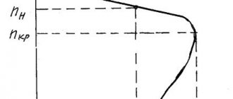
Figure 2 - Mechanical characteristics when switching from triangle to double star
A - triangle; B is a double star.
This type of speed control, in particular cases, switches speed with some temporary energy recovery. This switching method has found a niche in lifting mechanisms. You can see that as the number of pole pairs increases, the speed drops by half, but the critical moment also doubles, which gives us the ability to lift, but at a slower speed. This operating condition is called “traction” mode.
Comparing the powers, it is clear that the power changes slightly, and the speed changes in a stepwise manner by half.
Considering in more detail the mechanical characteristic during such a switching, we can notice that working at point 1, curve A, when switched on to a double star circuit, the asynchronous motor will move to point 2, curve B, and regenerative braking will begin to occur until the motor will switch to motor mode, and then to operating point 3, curve B. This braking is possible when the rotor speed of the asynchronous motor is greater than the synchronous speed. We looked at a particular example of such work in a previous article about back-braking, which described how loads are lowered in lifting mechanisms with energy released into the network.
Star-double star
Figure 3 – Star-double star switching circuit
Figure 4 - Mechanical characteristics when switching from star to double star
A - star; B is a double star.
The figure above shows that the critical moment remains the same, but the synchronous speed is halved.
Speaking of power, when switching to a double star, it doubles. When switching the windings, working at point 1, curve A, we will move to point 2, curve B, and from point 2 to point 3, just as in the previous case, regenerative braking will be carried out.
Add a comment
h4e.ru
Electric motor parameters: winding connection type
This is a very important parameter of a three-phase electric motor. All six terminals of the beginnings and ends of the windings are brought out into the engine bar. They can be connected either in a star or in a triangle.
Next to triangle/star
The plate indicates the rated voltage
– “220/380 V”
. This means that when a three-phase current with a voltage of 380 V is connected to the network, the motor windings must be connected in a star. An error in the connection will result in motor failure.
The rated current is also indicated as a fraction. In the described case, the value specified in the denominator is required.