In the article we will talk about asynchronous motors, namely about their connection to a 220 volt network without the use of a capacitor. The issue is quite relevant today, because ensuring energy efficiency in modern systems comes to the fore.
Asynchronous motor control circuit
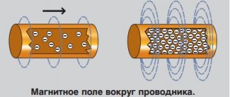
An asynchronous type electric motor is a device that operates on alternating current, in which the voltage is located in the rotor. The main purpose of the rotor current is to create torque through electromagnetic induction, which comes from the magnetic field of the stator winding.
There are two types of devices of this type: single- and three-phase. In the first case, the power unit is powered from a single-phase electricity source. The devices are low-power units used in home or office environments, where single-phase power is supplied from the mains and its poles.
Three-phase modifications operate, respectively, from power supplies with three phases. The motor operates in different configurations: delta or star, based on application requirements. The devices are characterized by high power and are used in the industrial sector.
Motor winding connection options
There are only two options for connecting the windings of asynchronous electric motors:
- according to the “star” scheme.
- according to the “triangle” option.
In the latter connection case, devices are used that are characterized by greater power supplied by the drive. However, when starting the power unit, a high level of starting current is produced, which poses a danger to any household appliance. If you connect according to the “star” scheme, you can achieve the smoothest start of the engine, because the current is small. You can't get much power out of the drive.
Connecting a triangle and star asynchronous motor
The connection diagram of a 380V electric motor to a 220V network, organized in a “triangle”, provides maximum operating power. When the power supply is 380 volts, then the coils are connected as a star. This is especially important, because at high voltages at start, the starting current also increases.
This may damage the electric drive. If there is a lack of power, you can start the engine with the coils connected using the first method, and after switching to operating mode, make the switch and turn on the windings using the “delta” method.
Asynchronous models have a simple design and are widely used in various types of applications. You should not ignore their low cost, which to some extent determines the distribution of components. They are connected to ordinary networks of 220 volts (single-phase), but what to do if there is a need to expand the power potential? The solution is simple - feed a three-phase power unit to a single-phase network. There is no need to use capacitor parts. Several schemes have been implemented to create such a connection, and each of them deserves attention. Let us consider each of them in detail and determine the strengths and benefits of implementation.
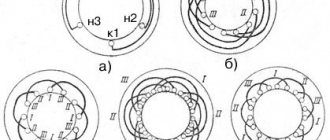
Star connection
Star triangle diagram
Many domestic electric motors already have a star circuit, you just need to implement a triangle. Essentially, you need to connect three phases and assemble a star from the remaining six ends of the winding. For better understanding, please view the star and delta motor drawing below. Here the ends are numbered from left to right, numbers 6, 4 and 5 are connected to three phases, as in the diagram:
Photo – Star and triangle electric motor
In a star connection with three terminals, or as it is also called a star-delta connection, the most important advantage is that the maximum power of the electric motor is generated. But at the same time, this compound is rarely used in production; it can be found much more often among amateur craftsmen. This is mainly because the circuit is very complex, and in powerful enterprises there is simply no point in organizing such a labor-intensive connection.
Read also: Woodworking machine Mogilev MDS 1 05 reviews
Photo – star connection
In order for the circuit to work, you will need three starters. The diagram is shown in the drawing below.
Photo - star-delta connection diagram
An electric current is connected to the first starter, which is designated K1, on one side, and the stator winding is connected to the other. The free ends of the stator are connected to starters K2 and K3. After this, the windings from the K2 starter are also connected to the remaining phases to form a triangle. When the K3 starter is switched into phase, the remaining ends are slightly shortened and you get a star circuit.
Note that the third and second magnetic starters cannot be turned on at the same time. This can lead to a short circuit and emergency shutdown of the electric motor. In order to avoid this, a kind of electrical blocking is implemented. The principle of its operation is simple - when one starter turns on, the other turns off, i.e. blocking opens the circuit of its contacts.
The operating principle of the circuit is relatively simple. When the first starter, designated K1, is connected to the network, the electric motor time relay also turns on the third starter K3. Afterwards, the engine starts in a star pattern and starts working with more power than usual. After a certain period of time, the time relay disconnects the contacts of the third starter and connects the second one to the network. The engine now operates in a delta pattern, reducing power slightly. When you need to turn off the power, the first starter circuit turns on, and during the next cycle the circuit is repeated.
It should be noted that we do not recommend implementing such a connection without certain experience and skills. In any case, when working independently, it is better to consult with professionals.
Video: engine 380 to 220
Starting the engine
As you already understand, the engine will be started without the use of a capacitor. To make a connection using this method, it is enough to have the most typical asynchronous motor. Authors of scientific books, among whom is V. Golik, indicate that the nominal speed of the motor rotor should be at the level of 1500 rpm, and not 3000. This is associated with the characteristics of the stator windings.
The power of power units is limited by the electrical parameters of power-type diodes and thyristors, which are 10 amperes, while the reverse voltage exceeds 300 volts. The 3 stator windings must be connected using a triangular connection. The pins are grouped on the terminal block using ordered jumpers.
The 220V voltage is supplied through an automatic safety switch. The connection is made parallel to one of the windings, let's define it as “A”. The remaining two (“B” and “C”) are connected in series with each other and in parallel with “A”. An electronic unit is installed at the outputs of one part, for example, “C”, let’s define it as “K”.
Let's consider a situation in which the block contact is always open and voltage is supplied uninterruptedly. With it, currents of types Ia and Ib+c will flow through the above-described circuits “A”, “B” and “C”. Resistive - inductive resistance levels are the same on all stator windings. This feature causes the current to be twice as high in chain “A” compared to the direction Ib+c. The phase coincidence of the circuits will be observed.
Each current individually creates magnetized fluxes near itself, which do not set the rotor element in motion. To ensure the operation of the motor, it is necessary to shift the angle of two magnetic fluxes or two currents between each other. It is for this task that an electronic unit (key) is implemented in the circuit. The design of the component allows it to short-circuit and open, bridging the second winding “B”.
Example of electric motor marking
To start the switch, a time interval is selected at which the current sinusoid has the highest amplitude indicator. The current strength in the third coil “C” is minimal, which is due to the presence of inductive reactance.
When short-circuiting resistance “B” in a common circuit with “C”, an inrush of current is created using a closed contact along the turns of the third winding. The contact itself grows quite quickly, after which it decreases under the influence of a decrease in the voltage amplitude, which smoothly tends to zero.
Also, a so-called time shift is formed in the system, which is marked ϕ. Thanks to the formed shear angle, a single strong magnetized flux is generated, which sets the rotor in motion.
The current supply in the third coil “C” during the operation of the switch differs from the voltage form implemented in a harmonic sine wave. Despite this, it does not in any way affect the generation of torque on the motor shaft. When a half-wave transitions from a sine wave to the sphere of “minus” indicators, the situation repeats itself, and the power unit itself spins further than before.
Using capacitors
When using a motor with a power of up to 1500 W, you can install only one capacitor - a working one. To calculate its power, use the formula:
I – operating current, U – voltage, P – engine power.
To simplify the calculation, you can do it differently - for every 100 W of power, 7 μF of capacitance is needed. Therefore, for a 750W motor you need 52-55uF (you need to experiment a bit to get the right phase shift).
In the event that a capacitor of the required capacity is not available, you need to connect in parallel those that are available, using the following formula:
Read also: Repair of a Soviet jack 5 tons
A starting capacitor is required when using motors whose power exceeds 1.5 kW. The starting capacitor works only in the first seconds of switching on to give a “push” to the rotor. It is turned on via a button parallel to the working one. In other words, it causes a stronger phase shift. This is the only way to connect a 380 to 220 motor through capacitors.
The essence of using a working capacitor is to obtain the third phase. The first two are zero and phase, which is already in the network. There should be no problems connecting the motor; the most important thing is to hide the capacitors away, preferably in a sealed, strong case. If the element fails, it may explode and harm others. The capacitor voltage must be at least 400 V.
Theory of V. Golik
This implementation is based on starting the motor using the existing element base. The power part of the electric switch, which is used for switching, includes the following powerful elements:
- two diodes: VD 1 and 2;
- thyristors: VS 1 and 2.
All these parts are connected using an ordinary bridge circuit. But, in this circuit, these elements implement another function - they shunt the winding of the connected motor through their “arms” of one diode and transistor. This is carried out immediately after the unit reaches the amplitude parameters of the sinusoid presented in the diagram. This connection creates a bidirectional electronic unit that responds to harmonic waves during operation. They come in two types:
- positive;
- negative.
Using diodes VD 3 and 4, a pulse voltage with two half-cycles is realized. This signal goes directly to the control circuit. It is limited and further stabilized using the resistor element R1 and the stabilizer VD5.
The signals aimed at opening the thyristors of the electric key come from transistors with 2 poles; in the figure they are marked as VT 1 and 2. The variable resistor R7, designed for 10 kOhm, performs the important function of regulating the opening moment of the thyristor.
In situations where its regulator is in the initial resistance position, the electrical unit is activated even at the lowest amplitude voltage that occurs in winding “B”.
The presence of the highest input resistor R7 allows you to turn off the switch. The circuit starts when the position of the slider of the above resistor corresponds to the highest current phase shift between the coils.
Electronic key on a triac
The start of the system is implemented quite simply - you need to move the R7 slider to a position that fully corresponds to the largest phase shift of the currents between the coils. Next, the regulator shifts, thereby determining the most stable operating mode, which directly depends on the level of applied load and the power of the electric motor. Power units with different ratings are interchangeable and widely represented on the domestic market.
Power components of the system, implemented for further operation with low-power motors, can be designed without cooling radiators in the design. When distributors operate at maximum resources, the use of a heat sink is mandatory.
Electrical units are used under 220V mains voltage. Individual components must be carefully insulated, thereby protecting them from accidental touches. Compliance with security measures is another important aspect when implementing a connection that must be observed.
How else can you connect an electric motor?
In addition to the star-delta connection, there are also several other options that are used more often:
- Many electricians advise installing a capacitor. Of course, this is the simplest solution, but at the same time you will immediately receive a sharp reduction in the power of the electric motor. To implement it, you only need a working capacitor. You need to connect the two contacts of the capacitor to zero and the third output of the electric motor. The result is a low-power unit of up to 1.5 W. But if your electric motor produces more power, then you need to add a starting capacitor to the circuit. But at the same time, if you have a single-phase connection, then the capacitor simply compensates for the lack of a third output; Photo – wiring diagram for a motor with capacitors
- If you have an asynchronous electric motor, then you can easily connect it to a star or delta, if desired, from 380 to 220 V. Such motors have three windings that are connected to each other in a star or delta; to change the voltage you just need to change the terminals that go to junction vertices;
- It is very important to carefully read the engine instructions, its certificate and passport. For many imported models, only a triangle connection to our 220 V voltage is possible. If you ignore this rule and connect them to a 220 V network using a star connection, the motors will simply burn out under high load. Also, you cannot connect a motor with a power of more than three kilowatts to the home network, otherwise short circuits will begin or even the RCD will burn out.
Complementing the point about capacitors, it should be noted that this component must be selected based on the minimum permissible capacity, gradually increasing it through trial methods to the optimal one required by the engine. If the electric motor sits without load for a very long time, it may simply burn out when connected to the network. Also remember that even after you have turned off the electric motors, the capacitors store voltage at their contacts.
Do not touch them under any circumstances, but preferably protect them with a special insulating layer that will help avoid accidents. Also, before working with them you need to do a discharge.
Schemes developed by V. Burlako
This methodology is also one of the actively used ones, which is determined by the implementation features. Despite the fact that the general principles of regulation are the same as those proposed by V. Golik, the schemes are still different.
Method 1 – start the motor with a triac key
At its core, the method is an improved implementation of the method presented by Golik. Here we have a significantly simplified connection diagram for a three-phase electric motor.
Example of thyristor operation diagram
Features of the new method include:
- the use of a single triac VS1 from TC-2-10, instead of the usual two thyristor components and a power unit. The part is also responsible for shunting the other winding “B” at the moment when the required voltage is reached. At the same time, the circuit current should be at a minimum;
- creating a phase shift for currents in all parallel windings. The indicator is common with the previous scheme and is in the range of 51 – 80 degrees, which is more than enough to ensure rotor rotation;
- using a key that is responsible for the operation of triac VS1. It is installed on a symmetrical type dinistor marked VS2, for each individual period of voltage harmonics. The key receives command signals from a phase shift chain that includes resistive-capacitive components;
- The phase shift through capacitor “C” is amplified by the total resistance of the components R1 R2. An auxiliary resistor R2 of 68 kilo-ohms performs the functions of component R7 from the circuit described above, providing regulation of the charging time of the capacitor, and, as a result, the moment when VS2 starts, and with its help, VS1.
The author also provides his recommendations for assembling and configuring the created circuit. It was developed for use with engines whose service life allows the rotor to spin up to 1500 rpm. The electrical power is 0.5 - 2.2 kilowatts.
If electronic keys are used on machines with high operating power, it is necessary to ensure heat dissipation. It is implemented using a VS1 triac. When making adjustments, it is necessary to look at the optimal state of adjusting the phase angle for the currents between the winding components. This will provide the engine with quiet, well-coordinated operation, without vibrations, noise, etc. For this purpose, you can change the ratings of the components of the phase shift circuit.
Triacs can be used in a variety of ways, the main thing is that they fully meet the characteristics of electromechanics. For example, an imported DB3 element is interchangeable with a domestically produced dinistor KR1125.
Starting the motor with high starting torques
Here, as in other circuits, a capacitor is not used. The technique is an excellent option for regulating the operation of electric motors that were assembled to provide rotational torques of 3000 per minute. This causes one feature in the circuit - changing the coil connection system to a star-shaped one. Previously, a triangular scheme was used. The process generates an order of magnitude higher torque, ensuring quick start of the rotor.
What are the differences between this scheme and the previous one? The first thing worth pointing out is the presence of an auxiliary electric switch (block), which is connected to winding “A”, thereby creating an additional phase shift of the current. It plays an important role when operating in difficult production conditions. In this case, the setup algorithm is similar to the previous one.
Three-phase motor in a single-phase network without capacitors: connection diagrams
Schematic diagram of the device
When faced with this scheme on the Internet, a person will be very happy. By the way, this decision was first published back in 1967.
The costs are small, why not try and create a device that provides trouble-free connection of an asynchronous three-phase motor to a single-phase network. But before you arm yourself with a soldering iron, you should read reviews and comments.
This scheme theoretically has the right to life, but in practice it generally does not work. Perhaps more careful tuning is needed. It is impossible to say definitively or give guarantees. Most forum users consider assembling such a device a waste of time, although some argue the opposite.
The following conclusions can be drawn from this dispute:
- the circuit can operate on an engine up to 2.2 kW and a rotation speed of 1,500 rpm;
- large power loss on the electric motor shaft;
- the circuit requires a careful option of the driving circuit C1R7, which must be adjusted so that the voltage on the capacitor opens and closes the switch, in all likelihood the transistors of the switch are in an off-duty mode, for this it is necessary to replace the resistor R6 or one of the R3R4;
- more reliable ways to connect a three-phase motor to a single-phase network are capacitors or a frequency converter.
The scheme was modernized in 1999. To start a three-phase motor in a single-phase network without capacitors, two simple circuits were debugged.
Both were tested on electric motors with powers ranging from 0.5 to 2.2 kW and showed pretty good results (start-up time is not much longer than in three-phase mode).
For financial savings, you can connect a three-phase motor using modern working circuits.
These circuits use triacs that are controlled by pulses of different polarities, as well as a symmetrical dinistor, which generates control signals in the flow of each half-cycle of the supply voltage.
Scheme No. 1 for low-speed electric motors
It is designed to start an electric motor with a rated speed that is equal to or less than 1500 rpm. The windings of these motors are connected in a triangle. The phase-shifting device in this circuit is a special chain.
By changing the resistance, we obtain a voltage on the capacitor that is shifted relative to the main supply voltage by a certain angle.
The key element in this circuit is a symmetrical dinistor. At the moment the voltage on the capacitor reaches a level at which the dinistor switches, a charged capacitor is connected to the control pin of the triac.
At this moment, the power bidirectional key is activated.
Thyristor converter
This development makes it possible to maintain the power parameters of motors with high efficiency when connected to a single-phase electrical network. The development belongs to V. Solomykov.
Thyristor converter author V Solomykova
The solution underlies all modern inverters, although it was developed taking into account an earlier, proven base.
Using a thyristor converter, it is possible to design voltage forms that will be as close as possible to the ideal for each phase. There will also be sine wave harmonics, which work well with asynchronous electric motors.
Energy supply from a 1-phase 220V power supply is carried out using protection - an automatic disconnector SF1 and a diode bridge based on D233V. At the output, power circuits are obtained thanks to the operation of thyristor switches VS1-6.
The current phase shift for the power supply of each motor coil with its own voltage is determined by the functioning of 2 main microcircuits:
- DD1 – for K176LE54
- DD2 – for R176 IR2.
The boards make it possible to generate voltage shift cycles from signals in all registers, and their combinations are supplied to the ports to regulate the operation of thyristors VS1 - 6, through independent transistors VT 1 - 6, according to a diagram that was previously planned.
Logical interpretation
A circuit like K176IR2 generates 2 separate 4-bit shift registers at once. They, in turn, have four Q outputs from each flip-flop. Each “starter” is a type D and is two-stage.
Chip K176IR2
Entry of statements into the register is also carried out through port D. An input for sending commands, clock type C, is also implemented. They go through ports D from the initial trigger, then shift along the direction of travel by 1 clock cycle.
The output from the Q register is reset when the R input receives voltage from the logic level. This reset is also called asynchronous reset.
Power section
The circuit also has a power part, which has its own principles and features of adjustment and further control. So, when voltage is applied to the circuit, the shift register of the DD2 board is reset. This in turn contributes to the completion of the charge of capacitors C2 further along the chain through element R5. When a charge occurs, DD1.1 is instantly triggered - which is, in fact, a logical component. It “allows” the pulse shift for further register DD2.
Example of K175LE5 circuit
When the register transitions to logical position 1, then a signal is sent to the base of its bipolar transistor - VT 1 - 6. It opens and sends a signal to its thyristor, namely to its control electrode.
As a result, we will get a three-phase voltage that will appear between the power terminals at the output. It is quite close to a sinusoidal shape, while being vectorially shifted to a maximum angle of 120 degrees.
The asynchronous type power unit, which is regulated according to this scheme, is capable of developing the highest power among all the options described. The frequency with which switching is carried out is selected experimentally, when tuning is carried out by selecting capacitive ratings: C 4, 5 or 6. Their levels are determined by the power of the motor itself.
Capacitor power is calculated using the following formula:
C = 0.01P (W) / n*1/30n (uF)
When the nominal rotor speed occurs, then the indicator n is determined as 1. R3 and R4, which are resistors, are removed after adjustment, and in place of the latter a capacitor is installed, the capacity of which is 0.68 microfarads. Next, what they do is solder an adjustment resistor rated at 15 kOhm. Install it to places A and B. Here the element performs the main function - it sets the speed of rotation of the rotor parts of the engine as accurately as possible.
Difference between start and run capacitors
To better understand why a starting capacitor is needed and what the features of their application are, you need to know about their differences. The main ones are the following:
- They have different installation locations. The worker is part of the circuit of working motor windings. The starter is part of the motor starting circuit.
- Capacitors differ in exactly when they are supposed to work. The starter is connected to the circuit during the first few seconds after starting. Then it is turned off in manual or automatic mode. The worker performs his functions during the entire time the engine is running.
- Each of them has its own functions. The starting one provides a phase shift between the windings to provide the main force when initially starting the motor. The worker ensures the rotation of the phases necessary for normal operation of the electric motor.
- Each capacitor type has different operating voltage requirements. The starting unit must be designed for one that exceeds the supply by 2-3 times. The worker must be designed for one that is 1.15 times greater than the incoming one.
In both cases, capacitors of the MBGO and MBGCh types are most often used.
general characteristics
In an inverter, the incoming single-phase line is rectified to DC and then "chopped" to three-phase AC, which is fed to the three-phase motor. The advantage of an inverter or variable frequency drive is that the operator has the ability to control the speed of the motor. He is helped in this by a huge number of user settings that allow you to select the selected speed change, as well as detection and protection against overloads of the power unit. Speed and torque compensation can also be adjusted. Although, it is worth noting that this method is not always the best solution.
An example of capacitorless starting of a 3-phase motor from the th phase network
The frequency converter helps create additional phases using capacitors that are connected between the phase and the “neutral” of the first phase to the motor winding. If this is implemented with a load motor, then the converter is static. They require a minimum load to generate reasonable pseudo-three-phase current, and it is often necessary to have a power rating greater than the maximum load to ensure good motor performance.
But, in the article we looked at 4 key schemes for implementing connections without using a capacitor, which have become more widespread in activity.
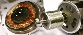
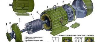
Design features of asynchronous three-phase motors
Asynchronous AC machines are a godsend for any owner. It’s just that connecting them to a household network turns out to be problematic. But you can still find a suitable option, the use of which will result in minimal power losses.
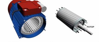
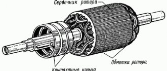
Before connecting a 380 to 220 motor, you need to understand its design. It consists of the following elements:
- The rotor is made according to the “squirrel cage” type.
- Stator with three identical windings.
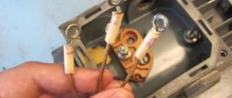
- Terminal box.
There must be a metal nameplate on the engine - all the parameters are written on it, even the year of manufacture. The wires from the stator go into the terminal box. Using three jumpers, all wires are connected to each other. Now let's look at what motor connection diagrams exist.
Conclusion
The circuits presented in today's article include only the necessary components, nothing superfluous. You can easily assemble them with your own hands, having minimal knowledge in the field of electrical engineering.
You can also begin to implement more complex techniques, for example, connecting a three-phase motor to single-phase power networks, but using modern electronic tools. The solution is more complex and therefore requires professional skills and knowledge in electromechanics.
Each user decides independently which scheme to use for their equipment. It is possible to start an asynchronous three-phase electric motor without power losses by using an industrial frequency converter.