Features of electrical wiring installation
All electrical installation work is carried out only after installing the electrical panel and meter. After which the locations of the switching equipment are determined. In order to correctly lay wires and install socket boxes, an inspection of the cable route, conditions for laying wiring and electrical products is carried out.
The precision of electrification guarantees not only an aesthetic appearance, but also the safety of the entire home. So, when installing a socket box as a distribution box, you must follow the installation rules, these are:
- Fix the socket box in a wall made of brick, concrete, plasterboard using a building mixture.
- Install the socket box flush with the wall surface with the wiring closed.
- To fasten the glass, use special clamping screws with plates.
When laying the cable, you should use special fasteners that will protect it from mechanical damage and act as grounding. When designing an electrical network through sockets and switches, it is necessary to use only high-quality equipment.
Recently, installation socket boxes with a more in-depth shape have become in great demand, so that the stock of wires formed by loops or folds can fit compactly without sharp creases.
Electrical wiring without junction box
The wiring architecture is drawn up taking into account the interests and wishes of the home owner. Electrical installation is a series connection of a circuit without junction boxes. The conductors are connected to the electrical system one after another and are supplied from each lighting point, socket, and switch directly to the distribution board.
Before starting work, a preliminary calculation of the expected amount of current consumption when using the planned electrical appliances and devices is carried out. The connection diagram includes the necessary set of wires and cables, installation of sockets, switches, and electrical appliances.
New electrical wiring requirements consider using only copper conductors. Contact connections of wires during electrical installation play an important role in any electrical system. They must be resistant to mechanical damage and safe.
Wiring connection methods
Bonding of electrical conductors in accordance with technical requirements and current instructions is carried out using soldering, crimping, crimping using appropriate tools. When choosing a contact connection method, it is necessary to consider what the fastening is for and where it will be placed.
At the points of connection and branching of wires, a reserve is always left for reconnection in the event of a malfunction. Today, the most versatile, efficient electrical connections are screwless terminals. Simple and convenient, suitable for all types of conductors of different cross-sectional diameters.
The clamp consists of a high-quality steel spring that is resistant to aggressive environments and a current bar made of electrolytic copper of special tinning, and is fixed on the contact area with a screwdriver. The terminal has no restrictions on currents and voltages; it even connects conductors to the sleeve. Meeting modern requirements, the clamp has a reduced size, due to which it does not take up much space in the electrical box.
Types of junction boxes
At the moment, the market offers a wide variety of junction boxes of a wide variety of designs and shapes.
Our article discusses only the box for connecting hidden wiring. Therefore, we will dwell in detail on products of this type.
So:
- First of all, all distribution boxes can be divided according to their shape. For hidden wiring, round ones are most often used. Their diameter and depth can vary greatly. So the diameter usually ranges from 60 to 100 mm, but the depth is usually from 30 to 50 mm. But if you have the right desire, you can find junction boxes for hidden wiring in other sizes.
- Square boxes are also widely used. Usually their sizes are comparable to those of round products. That is, starting from 60×60 mm and ending with products larger than 110 mm. The depth of square boxes usually does not exceed 30 - 50 mm.
- Rectangular junction boxes are also widely used. Here the range of sizes is even greater, but the total area is comparable to boxes of other shapes. Rectangular and square boxes for hidden wiring are used a little less frequently, although here it all depends on your wishes and technical conditions.
- In addition, junction boxes for hidden wiring differ in the material they are made of. According to clause 2.1.27 of the Electrical Installation Rules, they must be made of fireproof and non-combustible materials. When laying wires over combustible materials, metal junction boxes should be used. If the wire is laid using fireproof materials, then using fire-resistant plastic boxes is sufficient.
- If previously all distribution boxes were made hollow, now models with terminal blocks inside have appeared on the market. This allows for better connection of wires, and also helps to organize them inside the box. And although the price of such products is somewhat higher, their convenience is undeniable.
- Well, the last and very conditional division of distribution boxes is the presence of fastenings. It allows you to fix the products in the wall more efficiently and reliably, but if they are mounted on cement mortar, this advantage is very doubtful.
Methods for connecting wires in junction boxes
Putting the wires inside the box is half the battle. Now you need to choose a connection that is reliable and easy to maintain.
All cable line connections are divided into two main categories:
- Detachable, that is, the wiring can be disconnected and reconnected many times, without critical damage to the wire or connecting device. For example, a screw connection on terminal blocks.
- One-piece, that is, when the conductors are separated. the connection is destroyed. There is no big problem with this, it’s just that the cable gets shorter each time, and the connecting devices have to be purchased again.
The type of splicing when disconnecting boxes is selected based on the design of the overall network. If you plan to periodically disconnect one or two branches from a common box, it is better to choose a screw connection or reusable quick-release terminals.
For permanent connections that will not be dismantled for many years, the same terminals are used, only for one-time use. Despite the obvious drawback: the impossibility of reuse, such terminals provide more reliable contact compared to reusable ones.
If you use only copper conductor both in the backbone network and in subscriber branches, there are cheaper ways to permanently connect the wires:
- Twisting with welding.
Creates reliable contact, without the risk of sparking and heating of the wiring under heavy load. The connection is simple, but requires special equipment. As a last resort. You can melt the copper tips with a portable gas torch. - Twisting with soldering.
It is not as reliable as with tip reflow, but when using refractory solders, the connection practically does not lose strength, even when heated. The advantage is accessibility. A powerful soldering iron is easier to find than welding equipment. The basic rule: strength is ensured by twisting; we simply fill the voids with solder, improving contact. - Twisting with mechanical fixation (crimping). A questionable method, since there is a possibility of damage to current-carrying wires.
- There is nothing to say about ordinary twisting: although it is not prohibited, this technique is practically not used.
Direct connection (disconnection)
Is it possible to organize electrical wiring without junction boxes? When branching no more than 2 lines, it’s easy. Several conditions must be met:
- If the connection is made by twisting, soldering with refractory solder is required. Crimping can be used.
- "T" shaped connections are undesirable; it is better to make a "Y" shaped branch.
- After connecting and checking the quality of contact, the splice area must be carefully insulated and protected from moisture. Especially if the connection is made in hidden wiring (plaster wall) or on the street.
Advantages and disadvantages
The main advantage of using this wiring diagram is the absence of distribution boxes, which are usually installed at the top of the wall. As a result, there is no damage to the appearance of the finish.
It is worth noting that distribution boxes hidden under wallpaper or plaster can cause problems if there is a network fault. This is due to the fact that in order to get to the box, you will need to destroy part of the decorative design of the area above it. There are no such problems when using this installation scheme.
In addition, the advantages of this installation method include:
- installation costs for electrical wiring are significantly reduced;
- there is no need to form holes in the walls for distribution boxes;
- ease of installation and its ease.
However, it is worth noting that such cable installation requires a person to comply with all safety requirements.
In this case, all connection points must be accessible for routine inspection and necessary repairs. In this scheme, the weak point is the cable connections. Another disadvantage is that installation requires a large length of wires.
Despite a number of advantages, installing wiring in a house without using junction boxes is considered a necessary measure. When installing electrical wiring, distribution boxes increase the safety of its operation and also improve the reliability of the electrical network.
As you can see, electrical wiring without junction boxes is a wiring option that has some positive aspects. However, we should not forget about the disadvantages. Before installing wires according to such a scheme, you need to weigh all the pros and cons in order to make the optimal and correct decision in each specific situation.
Advantages and disadvantages of installation without junction boxes
The advantages of the method without branch boxes are:
- Reducing contact connections, which reduces the likelihood of emergency situations;
- Reduced labor costs at the installation stage;
- Simplicity of the connection diagram; in the absence of multiple ends in junction boxes, the likelihood of connection errors is reduced;
- For customers, reducing wiring elements, in this case junction boxes, reduces the cost of work.
- Improving the interior of the premises;
- During maintenance and repair, there is no need to destroy decorative elements on the upper sections of the walls.
The disadvantages include the following:
- Non-standard connections make it difficult to repair and maintain wiring by electricians who did not participate in the installation process;
- An increase in the number of groups, and therefore more wires. This statement is controversial; wires from boxes to sockets are excluded, so the difference in the length of the wires consumed is not significant.
- In some sections it is necessary to remove the outer sheath of the cable from the wires, as a result of which the double insulation element is missing.
Electrical wiring with distribution boxes
Typically, in electrical installations, a distribution box is used, through which the supply wires are connected to the wires going to sockets, switches, lamps, and so on.
Electrical wiring with junction box
If there are many outlets in the room, intermediate boxes are added. But, it should be taken into account that the box must have a correct and high-quality connection and there must be free access.
The diagram below shows an electrical installation with boxes, where the power wires come into the distribution box, and from it to the socket and intermediate box.
Wiring diagram with junction boxes
Connecting wires in a socket box
Features of installation of lighting networks without branch boxes
As in socket groups, the goal of the technique is to reduce contacts, labor costs and increase reliability. It is possible to use two-wire wires for single-key switches, but it is recommended to lay a cable with three wires. This is due to the fact that modern chandeliers and lamps have a terminal for the grounding wire on the body; it is better to comply with all safety requirements.
Network connection with single-key and two-key switches
For a better understanding, using a simplified diagram, we will consider connection methods: from the distribution board to the nearest switch we lay a phase wire, pull the neutral and grounding conductors to the lighting fixture. The grounding is attached to the lamp body, N is the neutral wire to the contact of the lamp socket.
The phase wire is fixed to the incoming contact of the switch, and a conductor is laid from the output contact to the free contact of the lamp socket. All the technology is not tricky, there is a complete absence of unnecessary contacts and junction boxes. If there are several elements in the lighting group in different rooms, we make connections in the box of the first switch and lay the line further. As in socket groups, connections can be made at the switch terminals. In the classic version, the contacts are twisted, insulated, and packaged at the bottom of the switch housing box.
The diagram shows the connection of single-key and two-key switches in one group.
Connecting a single-key switch
In this case, the power cable from the distribution panel is led directly into the switch box. The second wire in the diagram is the switching phase, connected to the lamp or hood. The neutral and ground wires are connected using flat terminals. The terminals are carefully placed in the box and the switch mechanism is installed.
What is a junction box
From the electrical panel, the wires disperse throughout the rooms in the house or apartment. Each room, as a rule, has more than one connection point: there are several sockets and a switch. To standardize the methods of connecting wires and collect them in one place, distribution boxes are used (they are also sometimes called branch boxes or junction boxes). They contain cables from all connected devices, the connection of which occurs inside the hollow housing.
In order not to look for wiring during the next repair, it is laid according to certain rules that are prescribed in the PUE - Rules for the Construction of Electrical Installations.
Electrical wiring rules
One recommendation is to carry out all connections and branch wires in the junction box. Therefore, the wires are run along the top of the wall, at a distance of 15 cm from the ceiling level. Having reached the branch point, the cable is lowered vertically down. A distribution box is installed at the branch point. It is where all the wires are connected according to the required circuit.
According to the type of installation, junction boxes are either internal (for hidden installation) or external. Under the internal ones, a hole is made in the wall into which the box is built. With this installation, the cover is flush with the finishing material. Sometimes during the renovation process it is covered with finishing materials. However, such installation is not always possible: the thickness of the walls or finishing does not allow it. Then a box for external mounting is used, which is attached directly to the wall surface.
Some forms of junction boxes
The shape of the junction box can be round or rectangular. There are usually four conclusions, but there may be more. The terminals have threads or fittings to which it is convenient to attach a corrugated hose. After all, it is more convenient to lay wires in a corrugated hose or plastic pipe. In this case, replacing the damaged cable will be very simple. First, disconnect it in the distribution box, then from the consumer (socket or switch), pull it and pull it out. Tighten a new one in its place. If you lay it the old fashioned way - in a groove, which is then covered with plaster - you will have to drill into the wall to replace the cable. So this is the recommendation of the PUE, which is definitely worth listening to.
What do distribution boxes generally provide:
- Increased maintainability of the power supply system. Since all connections are accessible, it is easy to determine the area of damage. If the conductors are laid in cable channels (corrugated hoses or pipes), replacing the damaged section will be easy.
- Most electrical problems arise in the connections, and with this installation option they can be inspected periodically.
- Installing distribution boxes increases the level of fire safety: all potentially dangerous places are located in certain places.
- Requires less money and labor than laying cables to each outlet.
Installation of wiring without junction boxes, save or lose
Good day, dear blog readers. The topic of this post will be installation of wiring without junction boxes and whether to do so or not.
Content
hide
1 Electrical installation with junction boxes
2 Electrical installation without junction boxes
3 We recommend reading:
I won’t say that often, but still this topic arises. The distribution box, as you know, is designed to connect power wires with wires going to sockets, switches, lamps, and so on.
The more connections, the larger the box can be and of course they should be installed so that they are accessible. Nobody wants to see box lids under the ceiling against the backdrop of expensive and beautiful wallpaper. And whatever one may say, the boxes end up under wallpaper or a layer of plaster, perhaps even a thick one if the electrician installed them before the plaster.
The question arises, is there a way out? It turns out there is, and let’s talk about it.
Electrical installation with junction boxes
Any electrical circuit in any room of our apartment consists of one or two switches, several sockets, lamps depending on the structure of the ceiling and, of course, several junction boxes.
In this case, the power wire comes from the machine located in the panel to the distribution box for lighting, and from it to the switch and to the chandelier or lamps, this concerns lighting. With sockets it’s almost the same, the power wire comes from the same panel, of course from another machine, into the distribution box of the socket group, where it is connected to the wires going to each of the sockets, let’s say there are three of them in the room.
The sockets, of course, can be spaced apart and then it makes sense to add another intermediate box. That is, in one outlet box the supply wire from the panel is connected, the wire going to the outlet and the supply wire to the intermediate box, in which it is connected to two wires going to the two remaining outlets. Usually this wiring option is used, but it should be noted that the connections in the box must be of high quality and correct, and of course there must be easy access.
Of course, I don’t want to bother with boxes, I want a minimum of connections, less dust, and sometimes the customer thinks that if he refuses distribution boxes, he will save on their cost and on the price for their installation.
Electrical installation without junction boxes
Let's look at an option that is also used for electrical installation, which in general is not prohibited, without the use of junction boxes. Let's imagine the same option with three sockets. The power is also taken from the panel from the machine and comes to the first socket and then through a cable to the second and third.
Now more details. We begin to cut the wire that comes into the first socket, that is, a three-wire cable in which there is a zero phase and grounding, and if we can break the neutral and phase wires, then the grounding wire is not supposed to be interrupted and it should reach this way without breaking to the grounding contacts of the third socket.
The stripped wires, neutral and phase, are connected to the corresponding incoming contacts of the socket, then the phase and neutral wires are stripped, which will go in a loop to the second socket, connected to the output contact and tightened well using a normal screwdriver. Naturally, in one contact there is the input and output of the neutral wire, and in the second contact there is the input and output of the phase wires.
You will have to tinker with the grounding, you can’t break it and naturally you can’t push it into the input and output of the contact group in the socket, so we strip the grounding wire, bend the exposed section of the wire in half and get two wires in contact with each other with an undivided core.
Then a piece of wire is taken, stripped on both sides, one end is attached to the bent bare ground wires and the resulting three bare sections are crimped with a sleeve for crimping wires, insulated, and the second stripped end of the wire is inserted into the ground contact of the socket and clamped well.
In this case, we get a non-breaking ground, and a separate branch as prescribed in clause 1.7.144 of the Electrical Installation Rules (Electrical Installation Rules) for PE (grounding conductors).
Next, we send the cable in the groove to the second outlet and then to the third. In this option, we interrupt the zero and phase, and use the contacts of the socket as a terminal block, but it’s good if the socket is branded and the contact group is powerful and of high quality.
Imagine a cheaper outlet, what contacts does it have? During operation, the contacts, if they are weak, can heat up; as the contacts cool down, they weaken and the wire may fall out of the contact or even burn out, then there will be no power in all other sockets. Often during installation, no matter what goes wrong with the laying of the wire, they cut through not only the zero and phase, but also the ground wire, in which case if for some reason the ground wire jumps out of the contact group and a current leak occurs, your ouzo, if you installed it , is unlikely to work. Remember this.
We can go even further. Crimping wires and making taps not only from grounding, but also making taps and crimping phase and neutral wires. Naturally, the sleeves for crimping are insulated, placed in the socket box, and the taps are connected to the corresponding contacts of the socket, which is installed in the socket box. In this case, the socket box also serves as a junction box; for greater convenience, longer socket boxes can be used, and all connections are available for preventive maintenance.
But in this installation option, the wire consumption is much greater, and when installers say that the wire consumption is almost the same, they are simply lying. So, decide for yourself what is easier, more profitable and more economical for you. Happy installation!
Best regards, Alexander & Igor.
Difficulty finding a junction box
Distribution boxes are designed to branch one power cable entering a room into many electrical points. Therefore, when installing new wiring or adding sockets and switches, you will have to find out where the distribution nodes are located.
Location of distribution boxes and sockets
When looking for a distribution box in a panel house, people face two problems:
- The box is not visible. It is hidden in the thickness of the wall. During repairs, the specialist makes every effort to ensure that this unit is as inconspicuous as possible and hidden under the plaster.
- To connect new wires, the box must be opened. This should be done with maximum accuracy down to one centimeter. Therefore, you will have to determine the shape and dimensions of the box before opening it. Nobody wants to spoil walls and wallpaper. You need to open the box as carefully and competently as possible.
Important. You need to know how many boxes there should be in a room
Some projects involve the presence of two distribution points in one room. In other cases, the box is through. With this design, it is one for two rooms.
Installation of lighting without a distribution box
Today, in modern apartments, houses, and office premises, wiring without junction boxes for lighting has become relevant, despite the high cable consumption. For installation of apartment lighting fixtures, a special place is allocated in the distribution panel.
The cable from the ceiling lighting fixture to the electrical panel is laid in corrugated pipes, replacing grooves. Such an electrification system guarantees a reliable connection without breaks in cable lines and ensures safety during the operation of electricity. For wiring, it is recommended to use a cable with insulation made of polymer or PVC compositions.
The cross-section of the wires must be selected based on the load of the power supply system, surface finishing material, and wiring method.
Installation without junction boxes is carried out only during repairs. For minor faults, simply remove the switch or socket and test the wiring.
Installation of junction boxes
As already indicated, junction boxes refer to additional protection of the indoor energy system. They are installed on any branches from the main highway. When laying electrical wiring, it is necessary to ensure that connections and current-carrying conductors do not touch the ceiling, floor and walls of the room. This condition is met due to the insulation of electrical wiring and the installation of junction boxes. To connect wires, soldering using solder and flux was previously widely used, but today reliable contact is ensured by twisting the wires and using screw terminal blocks to crimp them. However, it is necessary that the connection is not accessible and there is no open contact with the enclosing structure. It is these conditions that are provided by junction boxes. There are no restrictions on the number of boxes that can be installed in a room; you just need to proceed from the economic side and common sense. There are only some restrictions on the installation location. For example, in bathrooms, it is prohibited to install junction boxes closer than sixty centimeters from the bathtub or shower tray and below three meters from the floor level. As a rule, for safety reasons, junction boxes are installed outside these premises. Today, the following types of junction boxes are widely used:
- Junction boxes for internal installation - used when installing hidden electrical wiring;
- Open installation junction boxes - used when installing external or open wiring. Sometimes they are also called “overlay boxes”.
The main requirement for the installation of junction boxes is subsequent convenient maintenance and access. It is necessary to avoid situations where, in order to carry out work in the junction box, it is necessary to dismantle or destroy finishing or decorative elements.
When to use
This installation method is recommended in cases where the walls have expensive finishing. In this case, the wiring is carried out under the floor and without installing additional electrical equipment in the walls in the form of a junction box.
The PUE also indicates the moments when only this wire distribution scheme is used. According to the documentation, the ban on inserting cables into the junction box applies to lines that supply:
- electric stoves;
- air conditioners;
- heating boilers;
- all devices that consume a lot of electricity during their operation.
In these situations, a circuit breaker should be installed in the distribution panels for protection. A separate cable line is laid from it. The result is a circuit for powering a separate group of devices.
Bolted connections
Bolted connection
This connection is quite reliable, but cumbersome. It is not suitable for modern distribution boxes due to its dimensions, but for large old-style boxes it is just right. This method can be used to connect both homogeneous and dissimilar metals. The work is carried out as follows:
- A steel washer is placed on the bolt.
- The insulation is removed from the conductors and they are formed into a ring.
- The first ring is put on the bolt.
- Then comes another steel washer, which is placed on the bolt after the first.
- The second connecting wire is put on top.
- This entire “sandwich” is clamped with a nut.
- In the end, everything needs to be insulated.
It is this design that makes the contact bulky. If you need to connect several pairs of wires, then this option will not be the best.
Where and how to install distribution boxes
Usually the boxes are located under the ceiling at a distance of 100-200 mm from it. The specific value depends on the height of the room. If the wiring is hidden, then the product is placed inside the wall to a certain depth so that the surface of the cover is flush with the wall. For open-type electrical wiring, external boxes are suitable.
In accordance with the rules for the construction of electrical installations (PUE), it is important to provide free access to the junction box cover, which is necessary in case of inspection or troubleshooting. If the product is external and attached directly to the wall, then this condition is met automatically
When placing the device in a wall recess, two requirements must be met. Firstly, you need to know where it is installed, and secondly, you should ensure timely access to the product without compromising its aesthetics. If the latter can be neglected without violating the PUE, then the first requirement is mandatory and important.
You can maintain an aesthetic appearance by gluing beautiful wallpaper, and then carefully trim around the lid of the junction box without removing the part that is glued to it. When choosing alternative finishes, make sure that the color of the surface of the lid and the wall are identical. Try to make sure that if you need to remove the cover, the wall in this place does not collapse. If suspended ceilings are installed, then small hatches should be created to provide access to the boxes.
Electrical Wiring Safety
Upon completion of the installation of electrical wiring, it is necessary to carry out a set of measurements to ensure that the system is ready to use modern household equipment and appliances. Checking the functionality of the electrical panel, wires, cables, sockets, switches makes it possible to correct mistakes in a timely manner. Testing shows that:
- electrical wiring contacts have reliable grounding;
- connections are correctly connected;
- there is no extraneous voltage or damage to the insulation;
- automatic protection device matches the wiring.
Accurate measurements of electrical wiring can only be carried out with the help of electrical laboratory specialists. For testing, control and measuring equipment is used, which shows losses and electricity consumption. Sockets, switches, and lamps especially require preventive inspection to avoid short circuits.
A case from one's life
I personally had a case where everything seemed to be discussed with the client, the number of points (sockets, switches, lamps, junction boxes), their location, the nuances of subsequent wiring installation. They shook hands, an estimate was drawn up and materials for installation were purchased. According to the plan drawn up by joint efforts, the wiring was carried out. And then one day, when everything seems to be coming to an imminent conclusion, the drywall is screwed in and the painters putty on it, and I’m installing the transfer boxes and installation cups, before tomorrow’s installation of the fittings, the employer appears and stuns me with his idea: “I want to bed arch with lighting. How can I do that?".
Well, the builders immediately agreed to do the arch for a day of work. This idea didn’t inspire me much, since on the wall to which the arch will be attached there are only two sockets for connecting a charger and a floor lamp. It was not possible to run the wire to the junction box in the opposite corner. Moreover, it would be difficult to do this without damaging a couple of square meters of drywall.
That is why we had to fence off the garden, take power from the outlet, make a switch in a box with a switch and then lead it further to the arch lighting. This installation option is called wiring without a junction box. Below are diagrams for connecting a two-key switch and two light sources.
The video below shows a clear example of wiring without wiring in an apartment:
Junction box installation technology
So, let's talk directly about the process of installing and connecting the distribution junction box. If we talk about installing the box itself, there is nothing complicated or problematic here. Built-in versions of boxes are built into the walls, and overhead boxes are attached to the walls with dowels or self-tapping screws. Installation of a built-in box is more complex and time-consuming; in this case, it involves the creation of a special landing niche. In one of the walls, closer to the ceiling, it is necessary to make a niche of the appropriate size, this is where the box will be installed and secured with alabaster or cement mortar.
However, these procedures refer to the final stage of work. First of all, you should create a “network” of grooves - channels through which cables will be connected to the distribution box. The required number of drops to switch boxes and sockets must be in a strictly vertical position. In order to lay cables horizontally, it is recommended to take advantage of the gaps between the floor slabs and the walls.
After completing the preparation of the grooves and installation of the socket boxes, we proceed directly to the electrical wiring arrangement - an important part of this process will be the installation and connection of the distribution box. Often the process of connecting wires inside the junction box causes certain difficulties
To avoid them, we recommend marking each end of the cable in one way or another. For example, we connect the wire that supplies power from the electrical panel - we mark it with the appropriate word, we connect the cable from the socket block - the same thing, etc. Each individual electrical circuit that we connect to the distribution box must be labeled accordingly, in this case we will not face confusion later
Often the process of connecting wires inside a distribution box causes certain difficulties. To avoid them, we recommend marking each end of the cable in one way or another. For example, we connect the wire that supplies power from the electrical panel - we mark it with the appropriate word, we connect the cable from the socket block - the same thing, etc. Each individual electrical circuit that we connect to the distribution box must be labeled accordingly, in this case we will not face confusion later.
Cable cross-section
Now let’s take a break from the distribution box for a couple of minutes and say a few words about the cable cross-sections that are used when wiring a house or apartment. It is known that voltage is supplied to rooms from the electrical panel, as a rule, using a three or two-core cable with a cross-section of at least 4 square millimeters. This cross-section allows the cable to easily withstand any powerful power consumers. To connect sockets, cables with a cross-section of 2.5 square millimeters are used, and for a lighting system, a cross-section of one and a half square is sufficient.
Installation without junction boxes: general rules
Boilers, electric stoves, air conditioners and other household appliances with increased power consumption are powered separately from socket and lighting groups. In this case, it is desirable that each electrical appliance be powered by a separate cable through an automatic circuit breaker.
One outlet group can contain up to 8 outlets. The number of sockets and groups depends on the number of rooms and the power of consumers. This is done based on calculations and agreed with the customer before installation work begins.
The wire cross-section is selected based on the magnitude of the current loads. As a rule, copper wires with a cross-section of 2.5 mm² are chosen for socket groups, and 1.5 mm² for lighting.
The dependence of the cross-section of the copper wire on the current load is given in the table:
| Current value, A | Wire cross-section, mm² | Wire diameter, mm |
| 1 | 0,17 | 0,45 |
| 2 | 0,33 | 0,65 |
| 3 | 0,52 | 0,81 |
| 4 | 0,67 | 0,92 |
| 5 | 0,84 | 1,02 |
| 6 | 1 | 1,13 |
| 10 | 1,7 | 1,45 |
| 16 | 2,7 | 1,87 |
| 20 | 3,3 | 2,05 |
| 25 | 4,2 | 2,32 |
How to properly connect wires in a junction box
Let's turn to the PUE, which clearly states the requirements for connecting wires in junction boxes. Here are several options:
- soldering;
- crimping;
- terminals;
- using a bolted or screw connection.
Which of these options is considered the best? If we take into account two indicators: reliability and manufacturability, then the ideal option is twisting followed by soldering of the ends. You can only use twisting, and this is also a very high-tech option, although it has lower reliability compared to soldering.
Now the connected ends of the wires must be insulated, for which electrical tape is used. In this case, all connections must be installed in the distribution box in such a way that they are evenly distributed throughout the internal space of the device and do not touch each other.
Experienced electricians check all connections after installation work. They connect a load to each circuit and check whether any joint is overheating. If the connection of the wires becomes warm, it means that the area of their contact is small or the contact is loose. Therefore, such a joint must be redone.
Electrical wiring installation
in a house, apartment, garage, office, etc. is always performed with the installation of distribution (branch) boxes. At least one is always installed in each room.
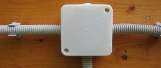
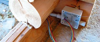
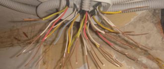
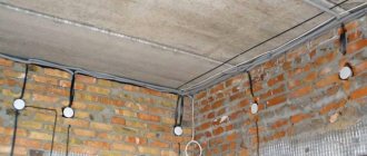
Electrical cables or wires extend from branch boxes to lamps, switches and sockets. They consist of a plastic case with a lid; they can be built-in for hidden electrical wiring (in Figures 3 and 4) and overhead for external wiring (in Figures 1 and 2).
Metal distribution boxes
are subject to mandatory grounding and are installed only when laying electrical cables in metal pipes. For example, in wooden houses and buildings in accordance with the rules and requirements.
Branch boxes vary in size and shape.
Large boxes should be used in places where there will be a large number of cables or wires. It is better to take round ones in shape than square or rectangular ones, because you won’t need to level them. And you can use a hole saw to drill a hole in drywall, block, brick, etc.
Before you start installing the box
it is necessary to make grooves and secure cables in them from the installation site to sockets, switches and lamps. Or secure the cables behind the drywall or panels that line the walls or ceiling.
With open wiring
the overhead box is attached to the ceiling or wall with 2 screws or dowels; just route the electrical cables through special seals.
It is necessary to cut a hole in the seals slightly smaller than the diameter of the cable. The illustration shows an option with dust seals. There are waterproof options with rubber seals and threaded plugs.
For installation of a built-in box
it is necessary to knock out or drill a recess into which the box must then be pressed flush. It is much easier to place the box in drywall.
Welding wires
Wire welding involves welding the ends of the wires using a special machine. At the end of the twist, a drop of welded wires is obtained. At the welding site, the twist is a single whole and the wires in this place do not oxidize.
The connection is high quality and durable. The disadvantages are that to produce high-quality welding, special equipment is required (special welding machine), work skills are required, labor intensity, and permanent connections.
You can also use an inverter welding machine for welding, but then the welding turns out to be fragile, since the welding voltage is 40-90 volts. Whereas for welding wires it is best to use a machine with an output voltage of 12-36 volts.
Expert opinion
It-Technology, Electrical power and electronics specialist
Ask questions to the “Specialist for modernization of energy generation systems”
Advantages and disadvantages of installation without distribution boxes In this case, if the sockets are spaced far enough from each other and we feel sorry for the cable, we make two distribution boxes. Ask, I'm in touch!
Features of twisting single-wire wires
Single-core wiring is more difficult to twist than multi-core wiring. There are a number of reasons for this:
The current-carrying core is made of a rigid metal rod. If the cross-section is large enough, then it will not be possible to bend it with your hands. The wire has low ductility
It is susceptible to kinks, so you need to work with it with extreme caution. When stripping insulation, the knife blade must be held at an angle of less than 30° to the axis of the wire. Otherwise, the tip will cut into the current-carrying core and damage it. Strippings are carried out no shorter than 50 mm
This is the only way to ensure a good connection. It is advisable to check the finished twist under load. During operation, it should not heat up more than a solid wire without a connection.
Tags: machine, beat, sconce, view, harm, choice, switch, house, , clamp, grounding, replacement, isolate, insulation, cable, how, design, circuit, , installation, voltage, neutral, crimping, soldering iron, connection , potential, rule, check, wire, project, laying, start, , work, size, repair, socket, row, garden, light, lamp, network, twist, connection, connection wire, ten, type, current, , shield, electrical panel, effect