Purpose and scope of application of the technique.
1.1 This document, method No. 5 “ Checking the performance of a residual current device (RCD )” establishes a method for testing the functionality of a residual current device (RCD) in electrical installations with voltages up to 1000 V for compliance with the requirements of regulatory documentation by electrical laboratory specialists.
1.3 The check is carried out on the basis of the requirements of GOST R 50571.16-99 (clause 612.6.1) and GOST R 50807-95.
2. Characteristics of the measured quantity, standard values of the measured quantity.
The object of testing is RCDs (residual current devices) of type A and AC, designed to operate only in 380\220 V alternating voltage networks with a solidly grounded neutral.
What is an RCD?
First, I’ll answer this basic question. “ RCD ” is an abbreviation that stands for “ Residual Current Device ”. RCD is also called this:
- Differential switch (the abbreviation “VD” in the name and on the RCD body comes from these words),
- Residual current switch (RCB),
- Residual current device,
- Differential protection switch,
- Automatic circuit breaker controlled by differential current.
From the name it is clear that the main properties of this device are to distinguish (differentiate), turn off, and protect.
And if you want to find out official information on RCDs, refer to GOST R 51326.1-99 .
Update. From 01.03.21 GOST R 51326.1-99 is not valid. Instead, GOST IEC 61008-1-2020 . For electromechanical RCDs (independent of supply voltage), there is additionally GOST 31601.2.1-2012 , for electronic ones - GOST 31601.2.2-2012 .
For RCBOs, the new GOST number is GOST IEC 61009-1 –2020.
What is the rated breaking current
The rated breaking current is the current value that can be turned off by the circuit breaker if it is equal to the highest operating voltage. This is the value for a mains short circuit that trips the fuse. As a rule, this figure is indicated on the packaging of the differential circuit breaker.
You may be interested in: Features of capacitor calculation
Rated electric current
What needs to be protected?
If we are talking about RCDs , then you need to understand that we are protecting people first of all. We protect against direct contact with parts of equipment and electrical wiring that contain dangerous potential. The potential there may be normal, to ensure normal operation (as at the phase terminal of a socket), or it may appear as a result of an accident (for example, 220 V may appear on the body of a washing machine due to poor insulation of the heating element).
PUE recommends installing RCDs on all outlet lines (PUE 7.1.71) , but usually they are not installed in dry rooms. But I think it’s better not to save money, but to put them on each group (line).
RCD is an additional protection against direct contact. The main protection against direct contact is primarily insulation and a circuit breaker. Everything is clear with insulation, but the machine should work if a phase hits the ground.
“It should” - but it won’t always succeed, since the short circuit current is sometimes insufficient to work on electromagnetic protection, but on thermal protection it can work in a second, or in an hour, or never. I have written about this more than once. In this case, it is necessary to install an RCD (PUE 7.1.72) .
The protection works on the principle of comparing the difference (differential) of currents in phase and zero. Current can “leak” for various reasons - poor insulation, short circuit, touch - but in all cases, if the leakage current is sufficient, the RCD will de-energize its line.
Here we can recall Kirchhoff’s first law for a closed loop, which can be expressed as follows: the current “flowing” from the power source is equal to the “flowing” current. If these currents are not equal, then there is a leak somewhere and the RCD should react.
By the way, leakage can occur not only from phase to ground. It can be from the neutral wire or to another phase. In any case, if the current finds a “loophole” and begins to leak out of the closed circuit, and when a certain value of the leakage current is reached, the RCD will turn off.
New-electro
1. GENERAL INFORMATION
Residual current devices that respond to differential current, along with overcurrent protection devices, are additional types of human protection from injury due to indirect contact, provided by automatically turning off the power. Overcurrent protection (when using protective grounding) provides protection to a person during indirect contact - by turning off the damaged section of the circuit with automatic switches or fuses in the event of a short circuit to the housing.
At low fault currents, a decrease in the insulation level, and also when the neutral protective conductor breaks, grounding is not effective enough, therefore, in these cases, the RCD is the only means of protecting a person from electrical shock.
Rice. 1. Residual current device (ABB)
The operation of protective shutdown as an electrical protective device is based on the principle of limiting (due to quick shutdown) the duration of current flow through the human body when it inadvertently touches energized elements of an electrical installation. Of all the known electrical protective equipment, the RCD is the only one that provides protection to a person from electric shock when directly touching one of the live parts.
Another, no less important property of an RCD is its ability to protect against fires and fires that occur at facilities due to possible damage to insulation, faulty wiring and electrical equipment.
Short circuits, as a rule, develop from insulation defects, ground faults, and current leaks to ground. The RCD, reacting to the leakage current to the ground or the protective conductor, in advance, before it develops into a short circuit, disconnects the electrical installation from the power source, thereby preventing unacceptable heating of the conductors, sparking, arcing and possible subsequent fire.
In some cases, the energy released at the site of insulation damage when leakage currents flow is sufficient to create a source of fire and, as a consequence, a fire. According to various domestic and foreign sources, a local fire of insulation can be caused by a rather insignificant power released at the leak site. Depending on the material and service life of the insulation, this power is only 40-60 W. This means that timely activation of a fire-prevention RCD with a setting of 300 mA will prevent the release of the specified power, and, therefore, prevent a fire.
Currently, there is an international classification of RCDs developed by the International Electrotechnical Commission (IEC). The common name is accepted - RCD - residual current protective device, translated as a differential (differential) current protective device.
2. PRINCIPLE OF OPERATION OF RCD
Functionally, an RCD can be defined as a high-speed protective switch that responds to differential current in the conductors supplying electricity to the protected electrical installation.
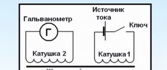
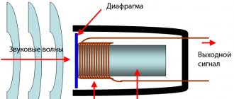
The main functional blocks of the RCD are shown in Fig. 2.
Rice. 2. RCD diagram with functional blocks
RCD is the differential current transformer I. In the vast majority of RCDs currently produced and operated throughout the world, a current transformer is used as a differential current sensor. In the literature on the design and use of RCDs, this transformer is sometimes called a zero-sequence current transformer - TTNP, although the concept of “zero-sequence” is applicable only to three-phase circuits and is used when calculating asymmetrical modes of multiphase circuits.
The trigger element (threshold element) 2 is usually performed on sensitive direct-acting magnetoelectric relays or electronic components. The actuator 3 includes a power contact group with a drive mechanism.
In normal mode, in the absence of differential current - leakage current, the operating load current flows I. The conductors passing through the window of the magnetic circuit form the back-to-back primary windings of the differential current transformer. If we denote the current flowing towards the load as I1, and from the load as I2, then we can write the equality:
I1 = I2
Equal currents in counter-connected windings induce equal, but vector counter-directed magnetic fluxes F1 and F2 in the magnetic core of the current transformer. The resulting magnetic flux is zero, and the current in the secondary winding of the differential transformer is also zero.
The trigger 2 is in this case at rest. When a person touches open conductive parts or the body of an electrical receiver on which an insulation breakdown has occurred, in addition to the load current I1, an additional current flows through the phase conductor through the RCD - leakage current (I0), which is differential (difference) for the current transformer.
The inequality of currents in the primary windings (I1 + I0 in the phase conductor) and (I2 equal to I1 in the neutral conductor) causes inequality of magnetic fluxes and, as a consequence, the appearance of a transformed differential current in the secondary winding. If this current exceeds the setting value of the threshold element of the starting element 2 , the latter is triggered and affects the actuator 3 .
An actuator, usually consisting of a spring drive, a trigger mechanism and a group of power contacts, opens the electrical circuit. As a result, the electrical installation protected by the RCD is de-energized.
To carry out periodic monitoring of the serviceability (operability) of the RCD, a testing circuit 4 . When you press the “Test” button, a tripping differential current is artificially created. Triggering of the RCD means that it is working properly.
3. TYPES OF RCD
According to the operating conditions, RCDs are divided into the following types: AC, A, B, S, G.
· RCD type AC - a residual current device that responds to an alternating sinusoidal differential current that occurs suddenly or slowly increases.
· RCD type A is a residual current device that responds to alternating sinusoidal differential current and pulsating direct differential current, occurring suddenly or slowly increasing.
· RCD type B is a residual current device that responds to alternating, direct and rectified differential currents.
· RCD type S – residual current device, selective (with shutdown time delay).
· RCD type G – the same as type S, but with a shorter time delay.
Of fundamental importance when considering the design of RCDs is the division of devices according to the method of technical implementation into the following two types:
RCDs that are functionally independent of the supply voltage (electromechanical). The source of energy necessary for operation - the performance of protective functions, including the shutdown operation - is the signal itself for the device - the differential current to which it reacts;
RCDs that are functionally dependent on the supply voltage (electronic). Their mechanism to perform the shutdown operation requires energy obtained either from the controlled network or from an external source. The use of devices that are functionally dependent on supply voltage is more limited due to their lower reliability, exposure to external factors, etc. However, the main reason for the less widespread use of such devices is their inoperability in the event of a frequent and most dangerous electrical installation malfunction in terms of the probability of electrical shock, namely - when the neutral conductor in the circuit up to the RCD towards the power source breaks. In this case, the “electronic” RCD, without power, does not function, and a potential dangerous to human life is carried to the electrical installation through the phase conductor.
The design of “electronic” RCDs produced in the USA, Japan, South Korea and some European countries (Fig. 3.1), as a rule, includes the function of disconnecting the protected electrical installation from the network when the supply voltage disappears. This function is structurally implemented using an electromagnetic relay operating in self-holding mode. The power contacts of the relay are in the on position only when current flows through its winding (similar to a magnetic starter).
Rice. 3.1. RCD with mains disconnect function
1 – Differential current transformer 2 – Electronic amplifier 3 – Test circuit 4 – Holding relay 5 – Control unit H – Load T – “Test” button
When the voltage disappears at the input terminals of the device, the relay armature drops, the power contacts open, and the protected electrical installation is de-energized. This design of the RCD provides guaranteed protection against injury to a person in an electrical installation and in the event of a break in the neutral conductor.
In the USA, RCDs are mainly used, built into socket blocks. At one site, for example, a small apartment, 10-15 devices are installed. Sockets that are not equipped with an RCD must be powered by a loop from socket blocks with an RCD.
Unfortunately, in our country, in contrast to the concept generally accepted in world practice, a number of enterprises produce electronic RCDs based on a standard circuit breaker. These devices function as follows. When a differential current occurs from a protective shutdown module containing a differential transformer and an electronic amplifier, either an electrical signal is supplied to the circuit breaker assembled with the module (to a modified current cut-off coil), or a mechanical effect is applied from the armature of the intermediate relay through the driver to the free tripping mechanism of the circuit breaker. As a result, the circuit breaker trips and disconnects the protected circuit from the network. If there is no voltage at the input terminals of such a device (for example, if the neutral conductor to the RCD is broken), firstly, due to lack of power, the electronic amplifier does not function, and secondly, there is no energy required to operate the circuit breaker.
Thus, in the event of a break in the neutral conductor in the supply network, the device is inoperable and does not protect the controlled circuit. Moreover, in this emergency mode (if the neutral conductor breaks), the danger of electric shock to a person is aggravated, since potential is carried through the phase conductor through the open contacts of the circuit breaker into the electrical installation. The user, believing that there is no voltage in the network, loses his usual vigilance in relation to electrical voltage and often makes attempts to eliminate the fault and restore power supply - opening the electrical panel, checking the contacts - thereby putting his life in mortal danger.
In European countries - Germany, Austria, France, electrical standards allow the use of RCDs only of the first type - independent of the supply voltage. RCDs of the second type are allowed to be used in circuits protected by electromechanical RCDs only as additional protection for end consumers, for example, for power tools, non-stationary electrical receivers, etc. Electromechanical RCDs are produced by leading European companies - Siemens, ABB, GE Power, ABL Sursum, Hager, Kopp, AEG, Baco, Legrand, Merlin-Gerin, Circutor, etc.
As a note, it should be noted that, unfortunately, a huge variety of counterfeits of RCDs and devices of unknown origin have appeared on the domestic market, often having an attractive appearance, but in terms of technical parameters, they do not even withstand acceptance tests.
The use of such devices, taking into account the special purpose of RCDs - the protection of human life and property, is completely unacceptable. Therefore, when purchasing an RCD, it is necessary to pay special attention to the availability of accompanying technical documentation, including necessarily two certificates - a certificate of conformity and a fire safety certificate.
There is a class of devices - RCDs with built-in overcurrent protection (RCBO), the so-called “combined” RCDs (Fig. 3.2).
Rice. 3.2. RCD with built-in overcurrent protection
1 – Current cut-off coil 2 – Bimetallic plate 3 – Differential current transformer 4 – Magnetoelectric release responding to differential current 5 – Test resistor 6 – Power contacts H – Load T – “Test” button
Almost all RCD manufacturers have RCDs with built-in overcurrent protection in their production program. As a rule, their share in the total volume of manufactured residual current devices does not exceed one or two percent. This is explained by the rather limited scope of their application - an insignificant, unchangeable load, an autonomous power receiver, etc. An illustrative example is the lighting of advertising billboards installed on street pavilions of public transport stops, where two or three fluorescent lamps are powered through a combined RCD with a rated operating current of 6 A and a rated residual current of 30 mA.
A design feature of an RCD with built-in overcurrent protection is that the mechanism for opening power contacts is triggered when it is exposed to any of three elements - a coil with a current cutoff core that responds to short circuit current, a bimetallic plate that responds to overload currents, and a magnetoelectric release that responds for differential current.
The use of an RCD with built-in overcurrent protection is advisable only in justified cases, for example, for single electricity consumers.
4. TECHNICAL PARAMETERS OF SAFETY DISCONNECT DEVICES
According to GOST R 50807-95, the following RCD parameters are standardized:
· Rated voltage (Un) – the effective voltage value at which the RCD operates. Un = 220, 380 V.
· Rated load current (In) – the current value that the RCD can pass in continuous operation. In = 6; 16; 25; 40; 63; 80; 100; 125 A.
· Rated residual current (I0n) – the value of the differential current that causes the RCD to trip under specified operating conditions. I0n = 0.006; 0.01; 0.03; 0.1; 0.3; 0.5 A.
· Rated non-tripping differential current (I0n0) – the value of the differential current that does not trip the RCD under given operating conditions. I0n0 = 0.5 I0n.
· Limit value of non-breaking overcurrent (Inm) – the minimum value of non-breaking overcurrent with a symmetrical load of two and four-pole RCDs or an asymmetric load of four-pole RCDs. Inm = 6 In.
· Overcurrent – any current that exceeds the rated load current.
· Rated making and breaking capacity (switching capacity) (Im) – the effective value of the expected current that the RCD is capable of turning on, passing during its opening time and turning off under given operating conditions without impairing its functionality. Minimum value Im = 10 In or 500 A (whichever is greater).
· Rated making and breaking capacity for differential current (Im) – the effective value of the expected differential current that the RCD is capable of turning on, passing during its opening time and turning off under given operating conditions without impairing its functionality. Minimum value Im = 10 In or 500 A (whichever is greater).
· Rated conditional short circuit current (Inc) – the effective value of the expected current that the RCD protected by the short circuit protection device can withstand under given operating conditions, without irreversible changes that impair its performance. Inc = 3000; 4500; 6000; 10,000 A.
· Rated conditional differential short-circuit current (I0c) – the effective value of the expected differential current that the RCD protected by the short-circuit protection device can withstand under given operating conditions without irreversible changes that impair its performance. I0c = 3000; 4500; 6000; 10,000 A.
· Rated tripping time Tn – the time interval between the moment of sudden occurrence of the tripping differential current and the moment of arc extinguishing on all poles.
The standard values of the maximum permissible shutdown time of an AC type RCD at any rated load current and the differential current values specified by the standards should not exceed those given in table. 4.1.
Table 4.1.
| Shutdown time Tn, s | |||
| I0n | 2 I0n | 5 I0n | 500 A |
| 0,3 | 0,15 | 0,04 | 0,04 |
The maximum shutdown time set in table. 4.1 also applies to RCDs of type A. In this case, tests of RCDs of type A are carried out at current values I0n, 2I0n, 5I0n and 500 A with a factor of 1.4 (for I0n > 0.01 A) and with a factor of 2 (for I0n = < 0.01 A).
Standard values of permissible shutdown and non-shutdown time for RCD type S at any rated load current over 25 A and values of rated differential current over 0.03 A should not exceed those given in table. 4.2.
Table 4.2.
| Differential current | I0n | 2 I0n | 5 I0n | 500 A |
| Maximum shutdown time | 0,5 | 0,2 | 0,15 | 0,15 |
| Minimum non-shutdown time | 0,13 | 0,06 | 0,05 | 0,04 |
In Fig. Figure 4.1 shows a graphical interpretation of the RCD response region depending on the differential current ratio.
Figure 4.1. Time-current characteristic of RCD
As an example of the design of an RCD that meets all the requirements of GOST R 50807-95, in Table. 4.3 shows the technical characteristics of ASTRO*UZO produced by OPP MPEI.
Table 4.3.
| Parameter name | Nominal value |
| Rated voltage Un, V | 220, 380* |
| Frequency fn, Hz | 50 |
| Rated load current In, A | 16, 25, 40, 63, 80* |
| Rated residual current (installation) I0n, mA | 10, 30, 100, 300* |
| Rated non-breaking differential current I0n0 | 0.5 I0n |
| Rated making and breaking (switching) capacity Im, A | 1500 |
| Rated conditional short-circuit current (thermal resistance) with a fuse-link connected in series 63 A Inc, A | 10000 |
| Rated shutdown time at rated differential current Tn, no more, ms | 30 |
| Operating temperature range, оС | -25 – 40 |
| Maximum cross-section of connected wires, mm2 | 25, 50* |
| Service life: electrical cycles, not less | 4000 |
| mechanical cycles, not less | 10000 |
*Depending on device modification
5. OPERATING MODE, ELECTRICAL PARAMETERS
Operating mode – continuous, long-term.
The RCD must disconnect the protected section of the network when a sinusoidal alternating or pulsating direct (depending on modification) leakage current appears in it, equal to the tripping differential current of the device (the tripping differential current of the RCD, according to the requirements of the standard, can have values in the range from 0.5 to the rated value, specified by the manufacturer).
An RCD that is functionally independent of the supply voltage should not operate when the mains voltage is removed and switched back on.
The RCD should not automatically reclose.
The RCD, which is functionally independent of the supply voltage, should not depend on the presence of voltage in the controlled network, and should remain operational in the event of a break in the neutral or phase wires.
The RCD should be triggered when the “Test” button is pressed.
The functionality of the operational control device (the “Test” button) must be maintained when the mains voltage drops to a value of 0.85 Un.
The design of the operational control device must exclude the possibility of mains voltage entering the circuit connected to the output terminals of the RCD when the “Test” button is pressed when the RCD is in the open state. This means that the test circuit must be connected to the input terminal of the RCD through a contact interlocked with the power contact group.
The RCD must be protected from short-circuit currents by a series protective device (ROD): a circuit breaker or fuse that meets the requirements of the relevant standards. In this case, the rated current of the RCD should not exceed the rated operating current of the RCD.
The RCD must be resistant to unwanted operation during current surges to ground caused by the inclusion of a capacitive load.
RCD tests for this parameter are carried out with a current pulse with a peak value of 200 A with a rise time of 0.5 μs.
The RCD must be resistant to overvoltage impulses.
Tests are carried out:
· application to the phase and neutral (phase, connected together and neutral) terminals of the RCD of a 6 kV pulse voltage package lasting at least 10 s;
· applying a pulse voltage of 8 kV to the live parts and base of the RCD (the RCD is fixed on a metal base) for at least 10 s.
· Pulse voltage is obtained using a generator that produces positive and negative pulses with a rise time of 1.2 μs.
· The insulation resistance of RCD electrical circuits in normal climatic conditions must be at least 10 MOhm.
· The insulation of the electrical circuits of the RCD must withstand the influence of a test voltage of 2200 V (rms value) alternating current with a frequency of 50 Hz for 1 minute without breakdown and surface overlap.
6. MARKING AND OTHER INFORMATION ABOUT RCD
Each RCD must be permanently marked with all or, for small sizes, part of the following data.
1. Name or trademark (brand) of the manufacturer.
2. Type designation, catalog number or series number.
3. Rated voltage Un.
4. Rated frequency, if the RCD is designed for a frequency other than 50 and/or 60 Hz.
5. Rated load current In.
6. Rated residual current I0n.
7. Rated maximum making and breaking switching capacity Im.
8. Rated conditional short-circuit current Inc.
9. Degree of protection (only if it differs from IP20);
10. Symbol [S] for type S devices, [G] for type G devices.
11. Indication that the RCD is functionally dependent on the mains voltage, if this is the case.
12. Designation of the control device control – the “Test” button – with the letter T.
13. Connection diagram.
14. Performance characteristics: type AC – symbol, type A – symbol.
Marking according to paragraphs. 2, 3, 5, 6, 8, 10, 12, 14 must be located so as to be visible after installation of the RCD. Information about the device according to paragraphs. 1, 7, 13 can be applied to the side or rear surface of the device, visible only before installation of the product. Information about the device according to paragraphs. 4, 9, 11, as well as the values of the Joule integral I2t and the peak current Ip should be given in the operational documentation. Terminals intended exclusively for connecting the neutral working conductor circuit must be marked with the letter “N”. Standard ambient temperature values (-5-40 °C) may not be indicated. The temperature range (-25-40 °C) is indicated by the symbol.
7. INSTALLATION LOCATION AND PURPOSE OF RCD
The installation of RCDs should be provided in ASUs located in rooms without an increased risk of electric shock, in places accessible for maintenance. The choice of location for installing RCDs in group circuits of electrical installations of buildings should be carried out taking into account the inclusion in the coverage area of the RCD, first of all, of sections of the electrical group circuit with the highest probability of electrical shock to people when touching live or open conductive parts of electrical equipment, which may become energized due to damage to the insulation (socket groups , bathrooms, shower rooms, washing machines, rooms with an increased risk of electric shock, etc.). RCDs intended for fire protection must be installed at the main input of the facility.
In multi-apartment residential buildings, it is recommended to install RCDs in group panels, including apartment panels; their installation is allowed in floor distribution panels; in individual houses - in ASUs and floor distribution panels.
In radial-type power supply schemes with a significant number of outgoing groups, it is recommended to install a common RCD at the input and a separate RCD for each group (consumer), subject to the appropriate selection of RCD parameters that ensure selectivity of their action.
When choosing a location for installing an RCD in a building, you should take into account: the method of installing electrical wiring, the material of buildings, the purpose of the RCD, operating conditions for electrical safety, RCD parameters, class of premises, wiring diagrams for electrical appliances, etc.
8. FEATURES OF USING RCD IN VARIOUS GROUNDING SYSTEMS
In the 7th edition of the PUE, the requirements for the implementation of group networks are formulated as follows (clauses 7.1.36, 7.1.45):
7.1.36. In all buildings, group network lines laid from group, floor and apartment panels to general lighting fixtures, plug sockets and stationary electrical receivers must be three-wire (phase - L, neutral working - N, and neutral protective - PE conductors). Combining zero working and zero protective conductors of different group lines is not allowed.
The neutral working and neutral protective conductors are not allowed to be connected to a common terminal. Conductor cross-sections must meet the requirements of clause 7.1.45.
7.1.45. The selection of conductor cross-sections should be carried out in accordance with the requirements of the relevant chapters of the PUE.
Single-phase two- and three-wire lines, as well as three-phase four- and five-wire lines when supplying single-phase loads, must have a cross-section of zero working N conductors equal to the cross-section of phase conductors.
Three-phase four- and five-wire lines when supplying three-phase symmetrical loads must have a cross-section of zero working N conductors equal to the cross-section of phase conductors, if the phase conductors have a cross-section of up to 16 mm2 for copper and 25 mm2 for aluminum, and for large cross-sections - at least 50% of the cross-section phase conductors, but not less than 16 mm2 for copper and 25 mm2 for aluminum.
The cross-section of PEN conductors must be at least the cross-section of N conductors and at least 10 mm2 for copper and 16 mm2 for aluminum, regardless of the cross-section of the phase conductors.
The cross-section of PE conductors must be equal to the cross-section of phase conductors with a cross-section of the latter up to 16 mm2, 16 mm2 with a cross-section of phase conductors from 16 to 35 mm2 and 50% of the cross-section of phase conductors with larger cross-sections.
The cross-section of PE conductors not included in the cable must be at least 2.5 mm2 - if there is mechanical protection and 4 mm2 - if there is none.
The classification of grounding systems is presented in clause 312.2 of GOST R 50571.2-94. The grounding system is a general characteristic of the electrical supply network and electrical installation of a building.
The PUE 7th edition contains the following grounding systems: TN-C, TN-S, TN-C-S, TT, IT (Fig. 8.1-8.5).
Figure 8.1. TN-C system
Figure 8.2. TN-S system
Figure 8.3. TN-CS system
Figure 8.4. TT system
Figure 8.5. IT system
The first letter in the designation of the grounding system determines the nature of the grounding of the power source:
T – direct connection of the neutral of the power source to the ground;
I – all live parts are isolated from the ground.
The second letter determines the nature of grounding of the open conductive parts of the building's electrical installation: T - direct connection of the open conductive parts of the building's electrical installation with the ground, regardless of the nature of the connection of the power source with the ground;
N – direct connection of open conductive parts of the building’s electrical installation with the grounding point of the power source.
The letters following N through a dash determine the nature of this connection - the functional method of constructing the neutral protective and neutral working conductors:
S – the functions of zero protective PE and zero working N conductors are provided by separate conductors;
C – the functions of the neutral protective and neutral working conductors are provided by one common conductor PEN.
In Russia, a system similar to TN-C is still used (Fig. 8.1), in which the open conductive parts of the electrical installation (casings, casings of electrical equipment) are connected to the grounded neutral of the source by a combined neutral protective and working conductor PEN, i.e. “nullified.” This system is relatively simple and cheap. However, it does not provide the necessary level of electrical safety.
The TN-S (Fig. 8.2) and TN-C-S (Fig. 8.3) systems are widely used in European countries - Germany, Austria, France, etc. In the TN-S system, all open conductive parts of the building's electrical installation are connected by a separate neutral protective PE conductor directly to the grounding device of the power source. When installing electrical installations, the rules require the use of a PE wire with yellow-green insulation markings for the neutral protective conductor.
In the TN-C-S system (Fig. 8.3), in the input device of the electrical installation, the combined neutral protective and working conductor PEN is divided into zero protective PE and zero working N conductors.
In the TN-C-S system, the neutral protective conductor PE is connected to all open conductive parts and can be grounded multiple times, while the neutral working conductor N must not be connected to the ground.
The most promising system for our country is the TN-C-S system, which allows, in combination with the widespread introduction of RCDs, to ensure a high level of electrical safety in electrical installations without their radical reconstruction.
In electrical installations with TN-S and TN-C-S grounding systems, the electrical safety of the consumer is ensured not by the systems themselves, but by residual current devices (RCDs), which operate more effectively in conjunction with these grounding systems and the potential equalization system.
In fact, the grounding systems themselves - without an RCD - do not provide the necessary safety. For example, if the insulation breaks down on the body of an electrical appliance or any device, in the absence of an RCD, this consumer is disconnected from the network by overcurrent protection devices - circuit breakers or fuse links.
The speed of overcurrent protection devices, firstly, is inferior to the speed of the RCD, and, secondly, depends on many factors - the short circuit current multiplicity, which in turn depends on the resistance of the conductors, the transition resistance at the point of insulation damage, the length of the lines, the accuracy calibration of circuit breakers, etc. The presence at the site of metal cases, fittings, etc., connected to a PE conductor, increases the risk of electrical shock, since in this case the probability of forming a circuit: “current-carrying conductor - human body - earth” is much higher. Only RCD provides protection against direct contact.
Related materials:
- Synchronous machine excitation device
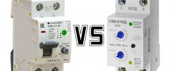
RCD, differential circuit breaker and RCBO - what is the difference?
All these devices successfully perform the function of switching off in case of current leakage, and have the letter “D” in their name - differential. The difference is that differential automatic machines have additional built-in overcurrent protection. That is, they additionally protect against overload currents and short-circuit currents, having a thermal and electromagnetic release on board.
Three differential protection devices - HP, IM, RCBO
In terms of functions, everything is simple, but in real life it may not be possible to distinguish RCDs from differential automatic devices the first time. I'm telling you.
The main external signs of an RCD (differential switch, VD):
- The RCD has the designation “VD” in its name - differential switch. True, only manufacturers who use Russian letters in their names have this.
- RCDs do not have a protective characteristic letter in front of the rated current value (most often this is the letter “C”).
- For RCDs, the letter “A” is written after the current value. Examples – 16A, 25A, 32A.
- On the side wall of the RCD they sometimes write “Differential Switch (RCD)”.
- The diagram indicated on the RCD body does not include designations of thermal and electromagnetic releases.
The main external features of differential automatic machines (IM and RCBO):
- The model name on the body always contains the letter “A” (BP, RCBO).
- The letter of the protective characteristic is always indicated (B, C, D).
- After the rated current, the letter indicating amperes is not placed. Examples – C16, C25, C32.
- On the side wall, as a rule, it is written that in front of us is a machine gun.
- The diagram shows the thermal and electromagnetic release.
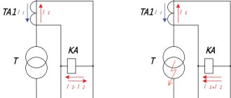
The differences in the HP, IM, RCBO circuits in terms of the presence of releases and overcurrent protection are visible below:
HP, IM, and RCBO - protection circuits are available only on the 2nd and 3rd circuits
differences between AD difavtomats and RCBOs , except perhaps in design. The IM has a series-connected circuit breaker and RCD in different housings, connected into a monolithic structure. AD is a more compact device.
The main external difference between differential protection devices and conventional circuit breakers is that in addition to the rated current In, the rated differential current IΔn (10, 30, 100, 300, 500 mA) is indicated on the HP, IM, RCBO.
By the way, PUE 7.1.76 directly states that it is recommended to use an RCD with an overcurrent protection device as a single device. This is necessary in order to guarantee the presence of protection and the correct protection current. After all, the consumer can install the machine at a higher current, or not install it at all. You never know.
In the second part of the article, we will consider the internal structure and differences of differential protection devices in more detail.
RCD response time
Based on the response time, RCDs are divided into two main types - S and G. They are used in switchboards of increased complexity to ensure selectivity in protected areas. For comparison, it should be noted that conventional protective devices operate when a current leak occurs in approximately 0.02-0.03 seconds. This option is ideal for those lines where there is only one RCD installed for the entire network.
Many schemes involve installing an input protective device and another one for each outgoing line. In the event of a malfunction in such a circuit, all devices should not operate simultaneously. To avoid this, there are selective RCDs type S with a response time delay of 0.15-0.5 seconds and type G with a delay of 0.06-0.08 seconds. As a result of such delays, the general input protection continues to remain in the operating position, and the entire apartment is not de-energized.
The tripping time is considered to be the interval between the sudden appearance of the differential tripping current and the moment when the arc is extinguished at each pole of the device. There is another concept called non-shutdown time limit. It is typical for RCD type S and is the maximum period of time from the onset of the breaking current in the main circuit of the device to the moment the breaking contacts begin to move. This indicator represents a time delay that ensures the selective action of RCDs operating in multi-level protection systems.
Modern high-quality electromechanical protective devices have operating speeds within 20-30 milliseconds. Such RCDs belong to the category of fast switches that operate before equipment protecting against overcurrents. As a result of operation, not only load currents are switched off, but also overcurrents.
Main characteristics of RCDs and Difavtomats
Characteristics marked on the RCD body
As an example in which I will show various characteristics, let’s take the TEXENERGO VD67 2P 16A/10mA .
Let's see what inscriptions and signs are located on its body.
RCD (differential switches) TEXENERGO VD67 and VD1-63. Front Panel Features
- TEXENERGO is a trademark. Anything can be written here, the essence remains the same.
- The orange button with the letter “T” is the “Test” button. When it is pressed, a leakage current is artificially created through the built-in resistor. The RCD should turn off. The consumer must carry out such a test himself, which is extremely inconvenient. But this must be done - after all, the RCD may fail, and at the right time it will not save you from electric shock.
- VD67, VD1-63 – RCD model (series).
- Rated current In (in the photo - 16 A, 32 A). Standard range of values: 16, 25, 32, 40, 50, 63 A. This is the current that the RCD can withstand for a long time. In this case, the RCD must be protected from overcurrents by a circuit breaker with the same rated current, or one step less. For example, for the RCDs shown in the photo, circuit breakers of 16 (13) A and 32 (25) A should be installed. If the RCD operates on several groups protected by separate circuit breakers, then the sum of the rated currents of the RCD should not exceed the rated current of the RCD. You should not expect that a situation will not occur when all groups have maximum load power. For example, if the RCD is 32A, then there may be 2 circuit breakers (16+16, or 25+6 A) or 3 circuit breakers (16+10+6 A).
- Rated operating voltage Ue and rated frequency (∼230V 50Hz). For four-pole circuit breakers, this voltage is 400 V.
- Rated leakage current IΔn (30 mA) (rated residual current). This is the most important parameter for differential protection devices. Standard range - 10, 30, 100, 300 mA. There is also a non-breaking differential current IΔn0 , the value of which is usually (in real modular everyday life - always) equal to 0.5 IΔn . At IΔn0, leakage shutdown should not occur. In other words, shutdown can occur in the range of 0.5 IΔn < IΔ < IΔn. If the leakage current is higher than or equal to IΔn (IΔ ≥ IΔn), shutdown must occur in any case. The larger IΔn, the shorter the shutdown time. In GOST R 51327.1-2010, table. Clause 5.3.8 is specified more precisely - at IΔn the shutdown time is no more than 0.3 s, and at 5IΔn and more the shutdown time should be no more than 0.04 s. In real life, the shutdown time for all models at any current IΔ ≥ IΔn is less than 0.04 s (but this is not exact))
- Rated conditional short-circuit current Inc (6000 A). In circuit breakers, a similar parameter is called “Rated maximum breaking capacity”, and is designated Icn. Why “conditional”? The fact is that the RCD is not designed to turn off the circuit during a short circuit - this should be done by a circuit breaker in the same circuit. The higher the Inc parameter of the RCD, the better the quality of its contact system. The standard range of values is 3000, 4500, 6000, 10000 A. I don’t know what this is connected with, but the value of 6000 is indicated on the body of this RCD, and in its passport Inc ≥10000 A.
- Type of RCD according to the type of differential current. There are two main types of RCDs for leakage current. The first one is AC. This is the most common and cheapest type, for pure alternating current, indicated by a sine wave (∼) , as in the photo. The second is A, it reacts not only to alternating, but also to direct (unipolar) pulsating current. This is necessary when the load has semiconductor input power circuits. More versatile type. There are devices that respond to other types of differential current, but they are practically not used in everyday life.
- Temperature range (-25 °C) – minimum operating temperature.
Characteristics indicated on the body of the differential pressure control valve
As I already said, IM and RCBOs have the same functions and characteristics as VD (RCD), but with the advantage they have thermal and electromagnetic overcurrent protection, like conventional circuit breakers. So it's short.
In our example, the TEXENERGO AD67-2 differential protection device on the body has the same characteristics related to differential protection:
AD67-2-difavtomat TEXENERGO
The differences (except for the design, which will be discussed later) relate to overcurrent protection. The main difference is the inscription “C25”.
Characteristics indicated on the body of the differential automatic RCBO
RCBO TEXENERGO for rated current 16A
In principle, the same thing - rated current 16A, type “C” shutdown characteristic.
Next, we will consider the parameters of the RCD that are not indicated on its body.
Number of RCD poles
There are only two options here -
- two-pole (2p, or 2P), for single-phase supply voltage,
- four-pole (4p, or 4P), for three-phase networks.
Unlike conventional circuit breakers, here another zero pole is added as an RCD. Since zero is needed for the normal functioning of the RCD.
Operating principle of RCD
RCDs can be divided into electromechanical and electronic based on the principle of measuring differential current.
Electromechanical RCDs are more reliable because they do not depend on parameters and surges in the supply voltage, and operation occurs only due to differential current. Just like in circuit breakers - their operation depends only on the flow and action of overcurrent.
Electronic RCDs have electronic circuitry inside that is critical to power supply. They are a little cheaper than mechanical ones, since they have a relatively small differential transformer inside, which plays the role of a sensor, and the electronics cost a penny. And their reliability is not yet high.
A detailed article about the differences between electronic and electromechanical RCDs, and how they behave in the event of a zero and phase loss.
How to distinguish an electromechanical RCD from an electronic one? First of all, according to the circuit, which in an electronic RCD contains a triangle indicating an operational amplifier:
HP, BP, and AVDT. The differential current amplifier is indicated by a triangle
The differential current amplifier can also be designated by a rectangle, but it must receive power wires from the phase and neutral wires.
Here is the diagram indicated on the RCD body at the top:
The upper part of the RCD is a diagram of an electromechanical RCD
Rated maximum making and breaking capacity Im
In this case, this characteristic is equal to 630 A and means that the RCD can turn on, conduct and turn off without negative consequences for itself.
Rated maximum differential making and breaking capacity IΔm
This is the same parameter as Im, but related to the differential current. Usually IΔm = Im.
RCD selectivity
This parameter implies time selectivity of the RCD, although there may also be differential current selectivity. Both selectivities are used so that RCDs installed closer to the input respond later, and closer to the load – earlier.
The RCD selectivity is general and delayed. Table from GOST R 51326.1-99
Please note that a gross error was made in the table of this GOST - the minimum non-tripping time of an RCD with a time delay at 2IΔn should not be 0.006 s, but 0.06 s. This error has been eliminated in the new GOST IEC 61008-1-2020.
The TEXENERGO differential protection devices discussed in the article do not have a time delay (general type of selectivity). RCDs and differential circuit breakers with a time delay are designated by the letter “S” (Selective).
Preparing to take measurements
7.1 Checking technical documentation
— The set of technical documentation should include:
— certificate of compliance with RCD GOST R51356-1-99;
— passport (operating manual) for the RCD with the manufacturer’s Quality Control Department stamp, date of manufacture, sales stamp, indication of the warranty period;
— accompanying technical documentation of the manufacturer.
— The accompanying technical documentation and marking of the RCD must contain information about the method and location of installation, the number of poles and the number of current-carrying conductors, rated voltage, rated current, rated breaking differential current, maximum shutdown time, rated non-breaking differential current, rated making and breaking capacity , as well as by differential current, limit value of non-tripping current under overcurrent conditions, rated conditional short circuit current, recommended switching circuit.
7.2 Checking the correct installation of the RCD in the electrical installation diagram. The check should include the validity of the RCD protection zone, compliance of its parameters with standardized values, parameters of overcurrent protection devices, and compliance of the overcurrent protection characteristics of the RCD with the calculated parameters of the network.
7.3 Checking the fixation of the RCD control in two extreme positions: “ON”; "OFF".
7.4 Checking the operation of the RCD when the operating voltage is turned on by pressing the “Test” button five times. Each time the button is pressed, the RCD contacts should open.
Download
For those who want to delve deeper into the topic, I am posting GOST, according to which RCDs (differential switches) are produced and selected. And a reference book on RCDs.
• GOST R 51326.1-99 / GOST R 51326.1-99 (IEC 61008-1-96) Automatic switches, controlled by differential current, for household and similar purposes without built-in overcurrent protection. Part 1. General requirements and test methods, pdf, 1.64 MB, downloaded: 1178 times./
• GOST R 50571.3-2009 (IEC 60364-4-41:2005) / GOST R 50571.3-2009 (IEC 60364-4-41:2005) Low-voltage electrical installations. Part 4-41. Security requirements. Protection against electric shock, pdf, 263 kB, downloaded: 1086 times./
• Dushkin N.D. and other RCD, educational and reference manual. / RCD - residual current devices, educational and reference manual., pdf, 8.44 MB, downloaded: 1610 times./
Let me remind you that the second part about the design of RCDs and automatic devices is here.
As always, I'd love to discuss!