Quartz resonators are passive components of electronic equipment and are intended for use in analog-digital circuits to stabilize and isolate electrical oscillations of a certain frequency or frequency band. The operating principle of this element is as follows: over a wide frequency band, the resistance of the device is capacitive in nature and only at some (operating) frequencies does it have a pronounced resonance (resistance decrease).
A quartz resonator has better characteristics than other devices for frequency stabilization (oscillatory circuits, piezoceramic resonators): such as stability in frequency (frequency drift) and temperature (change in resonance frequency depending on the ambient temperature).
The selective, pronounced resonant nature of the resistance of these components determines the main areas of application of quartz resonators - highly stable generators of clock signals and reference frequencies, frequency selection circuits, frequency synthesizers, etc.
Imported quartz resonators
| Currently available quartz resonators in housings of the following types: |
- HC-49/U - the closest domestic analogue - MD hull
- HC-49/US - difference from HC-49/U - lower height
- Quartz resonators for timing circuits at a frequency of 32.768 kHz
Components are certified in accordance with the international standard ISO 9002
Distinctive features:
- Low cost
- Industry standard
- Wide frequency range
- Low variation in operating frequency over time
- AT resonators
Appearance of HC-49 type housings Main technical characteristics:
| Parameter | Frame | Magnitude | Generation conditions | Dimensional drawing |
| frequency range | HC-49/U | 1.8 - 30 MHz | Fundamental harmonic |
| Housing | L, mm |
| HC-49/U | 13,0±0,2 |
| HC-49/US | 3,5 |
Technical parameters of quartz resonators:
- The AT resonator type is a special cut angle of the quartz crystal plate, at which the finished resonator has excellent frequency stability with respect to ambient temperature.
- Series equivalent resistance is the impedance of a resonator in series resonance.
- Frequency stability - frequency deviation from the nominal one. Usually expressed in parts per million of the nominal frequency of the resonator - Nx10 -6. The corresponding foreign marking is ppm (part per million).
- Temperature stability of frequency - change in frequency when the temperature of the resonator changes.
- Insulation resistance - resistance between the terminals of the resonator (usual values are on the order of MΩ)
- Load capacitance - any external capacitance connected in series with the resonator becomes an element that changes the resonance frequency. By varying the load capacitance, it is possible, within certain limits, to change the resonant frequency. Some manufacturers sometimes recommend in advance the use of standard load capacitance values to fine-tune the resonant frequency.
- Operating temperature range - the temperature range in which the resonator will operate with a frequency deviation not exceeding that specified for this type.
- Harmonics - for resonators with the AT cut type, which themselves are resonators of thickness-shear oscillations, in addition to the main resonance frequency, oscillations of odd harmonics (3xFmain, 5xFmain, 7xFmain) are also possible.
- “Aging” is a slow change in the parameters of the resonator after a certain period of time.
Standard frequency grid values for imported resonators, offered by Promelektronika JSC
The most common types of sealed quartz resonators in a metal case were produced in the USSR according to GOST 6503-67 “Sealed quartz resonators for oscillation frequencies from 0.75 to 100 MHz.”
According to this standard, resonators of the class under consideration must be produced in miniature (for the range from 5 to 100 MHz) and small-sized (for the entire frequency range).
They can be made with hard leads for insertion into the panel (see, for example, RKM-3), with soft leads for direct soldering in the circuit, and with hard tinned leads for soldering installation wires to them.
What is it and why is it needed
The device is a source that provides high-precision harmonic oscillations. Compared with analogues, it has greater operating efficiency and stable parameters.
The first examples of modern devices appeared on radio stations in 1920-1930. as elements that have stable operation and are capable of setting the carrier frequency. They:
- replaced crystal resonators operating on Rochelle salt, which appeared in 1917 as a result of the invention of Alexander M. Nicholson and were characterized by instability;
- replaced the previously used circuit with a coil and a capacitor, which did not have a high quality factor (up to 300) and depended on temperature changes.
A little later, quartz resonators became an integral part of timers and clocks. Electronic components with a natural resonant frequency of 32768 Hz, which in a binary 15-bit counter sets a time period equal to 1 second.
The devices are used today in:
- quartz watches, ensuring their accuracy regardless of ambient temperature;
- measuring instruments, guaranteeing them high accuracy of indicators;
- marine echo sounders, which are used in research and creation of bottom maps, recording reefs, shoals, and searching for objects in the water;
- circuits corresponding to reference oscillators that synthesize frequencies;
- circuits used in wave indication of SSB or telegraph signal;
- radio stations with DSB signal with intermediate frequency;
- bandpass filters of superheterodyne receivers, which are more stable and high-quality than LC filters.
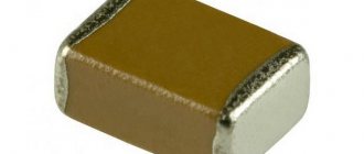
The devices are manufactured with different housings. They are divided into output ones, used in volumetric mounting, and SMD, used in surface mounting.
What is the load capacitance of a quartz resonator?
You've probably wondered why you need capacitors near the quartz in your favorite processor. How to choose them? Most people simply copy values from other people's circuits (“12MHz + 22pF?”, right?), I do this myself.
Fortunately, calculating the capacitance of these capacitors is simple.
Take, for example, the NX3225SA-12.000000MHZ quartz from NDK. This is good, stable (+/-15 ppm), but if you don't use the right capacitors, then the accuracy degrades greatly and 15 ppm is out of the question.
How do you know which container to attach? In each datasheet, a capacity is written on the quartz, onto which the quartz must be loaded in order for it to work accurately. It is called “Load Capacitance” or “Cl”, for our quartz it is 8pF. All we have to do is select the containers so that the formula is satisfied:
CL = (C1 * C2) / (C1 + C2) + Cstray
C1 and C2 are capacitors that are connected to the quartz, and Cstray is the capacitance of the conductors on the board, controller legs, etc. Usually no one counts it, but simply guesses: for example, the capacity of the Stm32 leg is 5 pf. To guess this capacity as accurately as possible, try to make the tracks from the quartz to the microcircuit shorter, and then the main contribution will come from the controller leg itself.
Now we easily find that the capacitance of C1 and C2 connected in series should be 8-5 = 3pF.
If we choose these capacitors equal, then (C1 * C2) / (C1 + C2) = C/2 = 3pF.
Hence, the capacitance of the capacitors should be 6pF.
Source
Properties of a quartz resonator
It is superior to previously existing analogues, which makes the device indispensable in many electronic circuits and explains the scope of use of the device. This is confirmed by the fact that in the first decade since its invention, more than 100 thousand devices were produced in the USA (not counting other countries).
Among the positive properties of quartz resonators that explain the popularity and demand for devices:
- good quality factor, the values of which - 104-106 - exceed the parameters of previously used analogues (they have a quality factor of 300);
- small dimensions, which can be measured in fractions of a millimeter;
- resistance to temperature and its fluctuations;
- long service life;
- ease of manufacture;
- the ability to build high-quality cascade filters without using manual settings.
Quartz resonators also have disadvantages:
- external elements allow you to adjust the frequency in a narrow range;
- have a fragile design;
- cannot tolerate excessive heat.
Review of Geyer Electronic quartz resonators
Geyer Electronic's Quartz Crystals series are available in a variety of temperature ranges to suit the applications in which they are used. The temperature range can be determined by the last symbol of the series, where the symbol “T” corresponds to the temperature range -40...80°C, “E” - -40...105°C. The absence of a symbol indicates that the operating temperature of the resonator is -20...70°C.
The main characteristics of these quartz resonators are indicated in tables 1, 2. All resonators reviewed comply with the RoHS directive 2011/65/EU. The word “available” in the tables means the possibility of special ordering resonators with these parameters.
Table 1. Main characteristics of clock quartz resonators in the frequency range 32.768 kHz
| Name | Operating temperature (temperature tolerance by frequency), °C | Frequency tolerance (df/F) at 25°C ±3°C, ppm | Load capacitance CL, pF | Aging (df/F) (first year) at 25°C ±3°C, ppm | Shunt capacitance, C0, pF | Used for applications, features, certification | Installation type | Dimensions, L×W×H, mm | |
| -20…70 | -40…85 | ||||||||
| KX-327FT | – | (-0.03 ±0.01 ppm/°C2) | ±20 (±10 available) | 12.5 | ±5 | 7 | Chip cards, mobile communications, medicine | SMD | 1.6×1.0×0.5 |
| KX-327RT | – | (-0.03 ±0.01 ppm/°C2) | ±20 (±10 available) | 12.5 | ±5 | 1,3 | mobile connection | SMD | 2.0×1.2×0.6 |
| KX-327NHT | – | (-0.035 ppm/°C2) | ±20 (±10 available) | 12.5 (7, 9 available) | ±3 | 1.6 | Miniature Communication Devices (AEC-Q200 Certified) | SMD | 3.2×1.5×0.8 |
| KX-327L | (-0.042 ppm/°C2) | KX-327LT (-0.042 ppm/°C2) | ±20 (±10 available) | 12,5 | ±3 | 0.8 | Industrial Application | SMD | 7×1.5×4 |
| KX-327S | (-0.034 ±0.006 ppm/°C2) | KX-327ST (-0.034 ±0.006 ppm/°C2) | ±20 (±10 available) | 12.5 | ±5 | 2 | Watches, micro-computers | SMD | 8.2×3.8×2.5 |
| KX-26 | (-0.042 ppm/°C2) | KX-26T (-0.042 ppm/°C2) | ±30 | 12.5 | ±3 | 1.3 | Watches and microcomputers | TNT | 2×6 |
| KX-38 | (-0.042 ppm/°C2) | KX-38T (-0.042 ppm/°C2) | ±20 | 6 or 12.5 | ±3 | 1.3 | Watches and microcomputers | TNT | 3×8 |
Table 2. Main characteristics of quartz resonators in the MHz range
| Name | Frequency range, MHz | Operating temperature (temperature tolerance by frequency), °C | Frequency tolerance (df/F) at +25°C ± 3°C, ppm | Load capacitance CL, pF | Aging (df/F) (first year) at 25°C ± 3°C, ppm | Peculiarities | Dimensions, L×W×H, mm | ||
| -20…70 | -40…85 | -40…105 | |||||||
| KX-4* | 2…80 | (±50 ppm; ±10…±50 ppm available) | KX-4T (±50 ppm; ±50…±100 ppm available) | – | ± 30 (±10…±50 available) | 8 (8…16 available) | ± 2 | Max. aging ±2ppm | 1,6×1,2×0,3 |
| KX-5* | 16…80 | (±50 ppm; ±30…±50 ppm available) | KX-5T (±100 ppm available ±30…±100 ppm) | KX-5E (±120 ppm; ±50…±120 ppm available) | ± 30 (±10…±50 available) | 8 (8…16 available) | ± 2 | Cert. AEC-Q200; Max. aging ±2ppm | 2,0×1,6×0,45 |
| KX-6* | 12…80 | (±50ppm; ±10…±50 ppm available) | KX-6T (±100 ppm; ±25…±100 ppm available) | KX-6E (±150 ppm; ±50…±120 ppm available) | ± 30 (±10…±50 available) | 9 (8…16 available) | ± 2 | Cert. AEC-Q200; Max. aging ±2ppm | 2,5×2,0×0,55 |
| KX-7* | 8…60 | (±50 ppm; ±10…±50 ppm available) | KX-7T (±100 ppm; ±20…±100 ppm available) | KX-7E (±120 ppm; ±30…±120 ppm available) | ± 30 (±10…±50 available) | 12 (available 7…20) | ± 2 | Cert. AEC-Q200; Max. aging ±2ppm | 3,2×2,5×0,8 |
| KX-9A* | 7,680…300,0 | (±50 ppm; available ±10…±70 ppm) | KX-9AT (±100ppm; ±20…±100 ppm available) | KX-9AE (±120 ppm; ±30…±120 ppm available) | ± 30; (±10…±50 available) | 16 (10…20 available) | ± 2 | Max aging ±2ppm | 5×3,2×1 |
| KX-12A* | 8,0…50,0 | (±50 ppm; ±10…±50 ppm available) | KX-12AT (±100 ppm; ±10…±100 ppm available) | KX-12AE (±120 ppm; ±30…±120 ppm available) | ± 50; (±10…±50 available) | 16 (10…20 available) | ± 2 | Max. aging ±2ppm | 5×3,2×1 |
| KX-12B* | 8,0…50,0 | (±50 ppm; ±10…±30 ppm available) | KX – 12BT (±100 ppm; ±30…±50 ppm available) | KX – 12BE (±120 ppm; ±50…±80 ppm available) | ± 30 | 16 (available 12…20) | ± 2 | Max. aging ±2ppm | 6×3,5×1 |
| KX-K** | 3,50…70,0 | (±50 ppm; ±15…±50 ppm available) | KX – KT (±100 ppm; ±25…±100 ppm available) | – | ± 30; (±10…±50 available) | 16 (available 12…30) | ± 5 | Budgeting | 10,3×4,2×3,8 |
| KX-KS** | 3,50…70,0 | (±50 ppm; ±15…±50 ppm available) | KX-KST (±100ppm; ±25…±100 ppm available) | – | ± 30; (±10…±50 available) | ± 5 | Budgeting; decrease profile | 10,3×4,2×3,8 | |
| KX-KSS** | 3,50…70,0 | (±50 ppm; ±15…±50 ppm available) | KX-KSST (±100ppm; ±25…±100 ppm available) | – | ± 50; (±10…±50 available) | ± 5 | Budgeting; decrease profile | 10,3×4,2×3,8 | |
| KX-3H** | 3,20…70,0 | (±50 ppm; ±15…±50 ppm available) | KX-3HT (±100 ppm; ±25…±100 ppm available) | KX-3HE (±120 ppm; ±35…±120 ppm available) | ± 30; (±10…±30 available) | ± 5 | Budgeting | 10,3×4,2×3,8 | |
| KX-49** | 1,84320…200 | (±50 ppm; ±5…±50 ppm available) | KX-49T | KX-49E | ± 30; (±5…±50 available) | 30 (10…30 available) | ± 5 | For IC watch | 11,3×13,6×4,9 |
| KX-39*** | 3,579545…40 | (±50 ppm) | KX-39T (±100 ppm) | – | ± 30 | 16 (available 12…20) | ± 3 | For IC watch | 3×10 |
| 30…70 | (±100 ppm) | KX-39T (±150 ppm) | – | ± 50 | 16 (available 12 … 20) | ± 3 | |||
| 40…100 | (-0.042 ppm/°C2) | KX-39T (-0.042 ppm/°C2) | – | ± 50 | 12 | ± 5 | |||
Shunt capacitance, C0, pF: * – 5, ** – 7, *** – for the frequency range 3.579545…40, 30…70 – 7; 40…100 – 3.
Quartz crystal holders must be firmly fixed and must not change their original position since production. Otherwise, microcracks may occur when the quartz crystal is compressed and bent. To prevent this, when installing into through holes, do not bend the resonator leads by more than 3 mm relative to the original position. Also, do not solder the housing for fixation to prevent the crystal from heating up. For this you need to use special devices.
There are no special comments on the soldering of the quartz resonator itself. Any polarity, no need to ground. Versions of surface-mount resonators are soldered by reflow according to the soldering conditions proposed by the manufacturer (Figure 2).
Rice. 2. Reflow soldering conditions for SMD resonators | Rice. 3. Installation of a quartz resonator for a microcontroller |
After soldering, the frequency of the quartz resonator may change by several ppm. The frequency will recover after several hours or days without any consequences for the quartz crystal. Cleaning is carried out using standard methods. When placing a quartz resonator on the board, it is also advisable to adhere to the following conditions:
- the closer to the generator, the better;
- there should be no tracks nearby that carry other signals that could cause interference;
- During storage, the following conditions must be observed: storage temperature: 25 ±5°C;
- Humidity: 60 ±15% RH.
The general storage temperature range is indicated for each series when ordering.
All questions regarding resonators, their selection and installation can be addressed to both the manufacturer and the distributor. Let's consider the general principles of choosing load capacitors and an external resistor using the example of a KX-K quartz resonator for a microcontroller with the required frequency of 24...25 MHz (Figure 3).
General data of the KX-K resonator, according to Table 1:
- load capacitance CL is 16 pF;
- temperature tolerance for permissible frequency deviation: ±30 ppm (20°C)/±50 ppm (-20…70°C);
- internal resonant resistance: R1 = 40 Ohm.
If the load capacitance is not matched with the load capacitance of the quartz resonator, then a shift in the resonant frequency will occur. The initial capacitance values of capacitors C1 and C2 for optimization should be 22 pF and 27 pF, respectively, because The crystal requires a load capacitance of 16 pF. The microcontroller is assumed to have internal 2 pF capacitances in OSC1 and OSC2. The parasitic capacitance of the electrical circuit is 3 pF. Thus, the final load capacitance is (all capacitance values in the formula below are in pF):
(22+2)×(27+2)/(22+2+27+2)+3=16,13
To simply start oscillations of a quartz resonator, the capacitance at the input OSC1 of the microcontroller is taken less than at its output OSC2.
To verify the safety of the trigger conditions, you need to test the circuit. To test, you must manually solder the resistors in series with the quartz resonator. Oscillations, even despite the resistance within limits, should be:
- for standard applications - 3...5 times the specified resonant resistance R1 (if R1 = 40 Ohms, then the range is 150...250 Ohms);
- for automotive applications - 5...10 times the specified resonant resistance R1 (if R1 = 40 Ohms, then the range is 250...500 Ohms)
Rice. 4. Installing an external resistor
An external resistor is recommended for operating frequencies below 4 MHz. At higher frequencies, the internal resistance of the microcontroller is usually sufficient. Capacitor C2 with an external resistor RV (Figure 4) form an RC circuit, i.e. low pass filter. Based on this, Rv is selected so that the critical frequency f is twice the nominal frequency of the resonator.
f = 1/2π RV C2
Example for C2 = 22 pF:
- for a 2 MHz quartz resonator, the desired critical frequency is 4 MHz, therefore, RV = 1.8 kOhm is selected;
- for a 6 MHz quartz resonator it is 12 MHz, which means Rv = 600 Ohm is selected.
Geyer Electronic produces high-quality quartz resonators of various sizes in SMD and THT mounting of popular frequency ranges for new applications. Well-established feedback between company employees and customers will allow you to select the appropriate quartz resonator for any task, depending on operating conditions, required characteristics, price and use in a specific application.
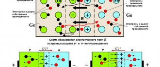
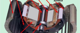
Operating principle of a quartz resonator
The device operates on the basis of the piezoelectric effect, which manifests itself on a low-temperature quartz plate. The element is cut out from a solid quartz crystal, observing the specified angle. The latter determines the electrochemical parameters of the resonator.
The plates are coated on both sides with a layer of silver (platinum, nickel, gold are suitable). They are then firmly fixed in the housing, which is sealed. The device is an oscillatory system that has its own resonant frequency.
When the electrodes are subjected to alternating voltage, the quartz plate, which has piezoelectric properties, bends, contracts, and shifts (depending on the type of crystal processing). At the same time, a back-EMF appears in it, as happens in an inductor located in an oscillatory circuit.
When a voltage is applied with a frequency that matches the natural vibrations of the plate, resonance is observed in the device. Simultaneously:
- the quartz element increases the amplitude of vibrations;
- The resonator resistance is greatly reduced.
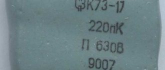
NI-8 12.73 MHz
Alexey Abyzov sent photographs of old quartz in an unusual design. The frequency is not marked, but according to the measurement results it is 12.73 MHz.
A mysterious resonator, in a massive metal case with a lamp base.
From the markings there is only the vague “G840”:
The first stage of the opening ended in a rather brutal tearing of the base from the inside, but... this did not bring me any closer to solving the contents. The main part is sealed, only two wires come out, one of which is in contact with the body. The internal volume is most likely sealed.
I did not dare resort to more destructive methods.
Unfortunately, neither the parameters nor the manufacturer are known. Indirectly, it is known that resonators in such a housing were produced by the Leningrad plant named after Kozitsky.
Quartz with unknown parameters. It got into the collection because it is the earliest quartz resonator known to me in a “classical” metal case, the same as the now widely used RK-170, RK-171, RG-08 and the like.
(photo by Igor Eremin)
| Unusual type of quartz. Moreover, the frequency is not indicated even in the passport, instead there is a dash. This sometimes happened; the frequencies of quartz resonators could be secret. |
At least, judging by the reference sheet, it lies in the range from 14 to 50 MHz.
at the Research Institute of Precision Instruments, now it is called “Etna”.
(photo by Igor Eremin)