Power supplies for radio and electrical equipment almost always use rectifiers designed to convert alternating current to direct current. This is due to the fact that almost all electronic circuits and many other devices must be powered from DC sources. A rectifier can be any element with a nonlinear current-voltage characteristic, in other words, passing current differently in opposite directions. In modern devices, planar semiconductor diodes are usually used as such elements.
Planar semiconductor diodes
Along with good conductors and insulators, there are many substances that occupy an intermediate position in conductivity between these two classes. Such substances are called semiconductors. The resistance of a pure semiconductor decreases with increasing temperature, unlike metals, whose resistance increases under these conditions.
By adding a small amount of impurity to a pure semiconductor, its conductivity can be significantly changed. There are two classes of such impurities:
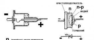
Figure 1. Planar diode: a. diode device, b. designation of a diode in electrical circuits, c. appearance of planar diodes of various powers.
The layer at the interface of p- and n-type semiconductors (pn junction) has one-way conductivity? conducts current well in one (forward) direction and very poorly in the opposite (reverse) direction. The structure of a planar diode is shown in Figure 1a. The basis ? a semiconductor plate (germanium) with a small amount of donor impurity (n-type), on which a piece of indium, which is an acceptor impurity, is placed.
Once heated, indium diffuses into the adjacent regions of the semiconductor, converting them into a p-type semiconductor. A pn junction occurs at the boundary of regions with two types of conductivity. The terminal connected to the p-type semiconductor is called the anode of the resulting diode, the opposite? its cathode. An image of a semiconductor diode on circuit diagrams is shown in Fig. 1b, appearance of planar diodes of various powers? in Fig. 1st century
The simplest rectifier
Figure 2. Current characteristics in various circuits.
The current flowing in a conventional lighting network is variable. Its magnitude and direction change 50 times within one second. A graph of its voltage versus time is shown in Fig. 2a. Positive half-cycles are shown in red, ? negative.
Since the current value varies from zero to the maximum (amplitude) value, the concept of the effective value of current and voltage is introduced. For example, in a lighting network the effective voltage value is 220 V? in a heating device connected to this network, the same amount of heat is generated over equal periods of time as in the same device in a 220 V DC circuit.
But in fact, the network voltage changes in 0.02 s as follows:
- the first quarter of this time (period)? increases from 0 to 311 V,
- second quarter of the period? decreases from 311 V to 0,
- third quarter of the period? decreases from 0 to 311 V,
- last quarter of the period? increases from 311 V to 0.
In this case, 311 V? voltage amplitude Uо. The amplitude and effective (U) voltages are related to each other by the formula:
When a series-connected diode (VD) and load are connected to an alternating current circuit (Fig. 2b), current flows through it only during positive half-cycles (Fig. 2c). This happens due to the one-way conductivity of the diode. Is such a rectifier called half-wave? During one half of the period there is current in the circuit, during the second? absent.
The current flowing through the load in such a rectifier is not constant, but pulsating. You can turn it almost constant by connecting a filter capacitor Cf of a sufficiently large capacity in parallel with the load. During the first quarter of the period, the capacitor is charged to the amplitude value, and in the intervals between pulsations it is discharged to the load. The tension becomes almost constant. The greater the capacitor capacity, the stronger the smoothing effect.
A rectifier is a device for converting alternating voltage to direct voltage. This is one of the most common parts in electrical appliances, ranging from hair dryers to all types of power supplies with DC output voltage. There are different rectifier circuits and each of them copes with its task to a certain extent. In this article we will talk about how to make a single-phase rectifier and why it is needed.
Definition
A rectifier is a device designed to convert alternating current into direct current. The word “constant” is not entirely correct; the fact is that at the output of the rectifier, in the sinusoidal alternating voltage circuit, in any case there will be an unstabilized pulsating voltage. In simple words: constant in sign, but varying in magnitude.
There are two types of rectifiers:
- Half-wave. It rectifies only one half-wave of the input voltage. Characterized by strong ripples and low voltage relative to the input.
- Full-wave. Accordingly, two half-waves are rectified. The ripple is lower, the voltage is higher than at the rectifier input - these are two main characteristics.
What does stabilized and unstabilized voltage mean?
Stabilized is a voltage that does not change in value regardless of the load or input voltage surges. For transformer power supplies, this is especially important because the output voltage depends on the input voltage and differs from it by Ktransformation times.
Unstabilized voltage - changes depending on surges in the supply network and load characteristics. With such a power supply, due to drawdowns, the connected devices may malfunction or become completely inoperable and fail.
Output voltage
The main quantities of alternating voltage are amplitude and effective value. When they say “in a 220V network,” they mean the effective voltage.
If we talk about the amplitude value, then we mean how many volts from zero to the top point of the half-wave of a sine wave.
Omitting the theory and a number of formulas, we can say that the effective voltage is 1.41 times less than the amplitude. Or:
Uа=Uд*√2
The amplitude voltage in a 220V network is equal to:
220*1.41=310
Scheme
A half-wave rectifier consists of a single diode. It simply does not allow the reverse half-wave to pass through. The output produces a voltage with strong ripples from zero to the amplitude value of the input voltage.
To put it in very simple terms, in this circuit half of the input voltage is supplied to the load. But this is not entirely correct.
Full-wave circuits pass both half-waves from the input to the load. Above in the article, the amplitude value of the voltage was mentioned, but the voltage at the output of the rectifier is also lower in value than the actual alternating voltage at the input.
But, if you smooth out the ripples using a capacitor, then the smaller the ripples, the closer the voltage will be to the amplitude.
We'll talk about smoothing ripples later. Now let's look at the diode bridge circuits.
There are two of them:
1. Graetz rectifier or diode bridge;
2. Midpoint rectifier.
The first scheme is more common. It consists of a diode bridge - four diodes are connected to each other by a “square”, and a load is connected to its shoulders. The bridge type rectifier is assembled according to the diagram below:
It can be connected directly to a 220V network, as is done in modern switching power supplies, or to the secondary windings of a network (50 Hz) transformer. Diode bridges according to this scheme can be assembled from discrete (individual) diodes or use a ready-made diode bridge assembly in a single housing.
The second scheme - a rectifier with a midpoint cannot be connected directly to the network. Its meaning is to use a transformer with a tap from the middle.
At its core, these are two half-wave rectifiers connected to the ends of the secondary winding; the load is connected with one contact to the diode connection point, and the second to the tap from the middle of the windings.
Its advantage over the first circuit is the smaller number of semiconductor diodes. The disadvantage is the use of a transformer with a midpoint or, as they also call it, a tap from the middle. They are less common than conventional transformers with a secondary winding without taps.
Ripple Smoothing
Power supply with pulsating voltage is unacceptable for a number of consumers, for example, light sources and audio equipment. Moreover, permissible light pulsations are regulated in state and industry regulations.
To smooth out ripples, filters are used - a parallel capacitor, an LC filter, various P- and G-filters...
But the most common and simplest option is a capacitor installed in parallel with the load. Its disadvantage is that to reduce ripple on a very powerful load, you will have to install very large capacitors - tens of thousands of microfarads.
Its operating principle is that the capacitor is charged, its voltage reaches amplitude, the supply voltage after the point of maximum amplitude begins to decrease, from this moment the load is powered by the capacitor. The capacitor discharges depending on the resistance of the load (or its equivalent resistance if it is not resistive). The larger the capacitance of the capacitor, the smaller the ripple will be when compared with a capacitor with a lower capacitance connected to the same load.
In simple words: the slower the capacitor discharges, the less ripple.
The discharge rate of the capacitor depends on the current consumed by the load. It can be determined using the time constant formula:
t=RC,
where R is the load resistance, and C is the capacitance of the smoothing capacitor.
Thus, from a fully charged state to a completely discharged state, the capacitor will be discharged in 3-5 t. It charges at the same speed if the charge occurs through a resistor, so in our case it does not matter.
It follows that in order to achieve an acceptable level of ripple (it is determined by the load requirements for the power source), you need a capacitance that will be discharged in a time several times greater than t. Since the resistance of most loads is relatively small, a large capacitance is needed, therefore, in order to smooth out ripples at the output of the rectifier, electrolytic capacitors are used, they are also called polar or polarized.
Please note that it is highly not recommended to confuse the polarity of an electrolytic capacitor, because this can lead to its failure and even explosion. Modern capacitors are protected from explosion - they have a cross-shaped stamping on the top cover, along which the case will simply crack. But a stream of smoke will come out of the condenser; it will be bad if it gets into your eyes.
The capacitance is calculated based on the ripple factor that needs to be ensured. In simple terms, the ripple coefficient shows by what percentage the voltage sags (pulsates).
To calculate the capacity of the smoothing capacitor, you can use the approximate formula:
C=3200*In/Un*Kp,
Where In is the load current, Un is the load voltage, Kn is the ripple factor.
For most types of equipment, the ripple coefficient is taken to be 0.01-0.001. Additionally, it is advisable to install a ceramic capacitor of as large a capacity as possible to filter out high-frequency interference.
How to make a power supply with your own hands?
The simplest DC power supply consists of three elements:
1. Transformer;
2. Diode bridge;
3. Capacitor.
If you need to get high voltage, and you neglect galvanic isolation, then you can exclude the transformer from the list, then you will get a constant voltage up to 300-310V. This circuit is located at the input of switching power supplies, for example, like the one on your computer.
This is an unregulated DC power supply with a smoothing capacitor. The voltage at its output is greater than the alternating voltage in the secondary winding. This means that if you have a 220/12 transformer (the primary is 220V and the secondary is 12V), then at the output you will get 15-17V constant. This value depends on the capacitance of the smoothing capacitor. This circuit can be used to power any load, if it does not matter to it that the voltage can “float” when the supply voltage changes.
Important:
A capacitor has two main characteristics - capacitance and voltage. We figured out how to select the capacitance, but not how to select the voltage. The capacitor voltage must exceed the amplitude voltage at the rectifier output by at least half. If the actual voltage on the capacitor plates exceeds the nominal voltage, there is a high probability of its failure.
Old Soviet capacitors were made with a good voltage reserve, but now everyone uses cheap electrolytes from China, where at best there is a small reserve, and at worst it will not withstand the specified rated voltage. Therefore, do not skimp on reliability.
The stabilized power supply differs from the previous one only by the presence of a voltage (or current) stabilizer. The simplest option is to use L78xx or other linear stabilizers, such as the domestic KREN.
This way you can get any voltage, the only condition when using such stabilizers is that the voltage to the stabilizer must exceed the stabilized (output) value by at least 1.5V. Let's look at what is written in the datasheet of the 12V stabilizer L7812:
The input voltage should not exceed 35V, for stabilizers from 5 to 12V, and 40V for stabilizers 20-24V.
The input voltage must exceed the output voltage by 2-2.5V.
Full version of the datasheet https://www.jameco.com/Jameco/Products/ProdDS/889305.pdf
Those. for a stabilized 12V power supply with a stabilizer of the L7812 series, it is necessary that the rectified voltage lies in the range of 14.5-35V, in order to avoid sags, it would be an ideal solution to use a transformer with a 12V secondary winding.
But the output current is quite modest - only 1.5A, it can be amplified using a pass transistor. If you have PNP transistors, you can use this circuit:
It shows only the connection of a linear stabilizer; the “left” part of the circuit with the transformer and rectifier is omitted.
If you have NPN transistors like KT803/KT805/KT808, then this one will do:
It is worth noting that in the second circuit, the output voltage will be 0.6V less than the stabilization voltage - this is a drop at the emitter-base transition. To compensate for this drop, diode D1 was introduced into the circuit.
It is possible to install two linear stabilizers in parallel, but this is not necessary! Due to possible deviations during manufacturing, the load will be distributed unevenly and one of them may burn out because of this.
Install both the transistor and the linear stabilizer on the radiator, preferably on different radiators. They get very hot.
Regulated Power Supplies
The simplest adjustable power supply can be made with an adjustable linear stabilizer LM317, its current is also up to 1.5 A, you can amplify the circuit with a pass transistor, as described above.
Here is a more visual diagram for assembling an adjustable power supply.
To get more current, you can use a more powerful adjustable stabilizer LM350.
The last two circuits have a power-on indication, which shows the presence of voltage at the output of the diode bridge, a 220V switch, and a fuse for the primary winding.
Here is an example of a regulated battery charger with a thyristor regulator in the primary winding, essentially the same regulated power supply.
By the way, a similar scheme is used to regulate the welding current:
Conclusion
A rectifier is used in power supplies to produce direct current from alternating current. Without its participation, it will not be possible to power a DC load, for example an LED strip or a radio.
Also used in a variety of chargers for car batteries, there are a number of circuits using a transformer with a group of taps from the primary winding, which are switched by a flip switch, and only a diode bridge is installed in the secondary winding. The switch is installed on the high voltage side, since the current there is several times lower and its contacts will not burn from this.
Using the diagrams from the article, you can assemble a simple power supply both for constant operation with some device and for testing your electronic homemade products.
The circuits are not characterized by high efficiency, but they produce a stabilized voltage without much ripple; the capacitance of the capacitors should be checked and calculated for a specific load. They are perfect for low-power audio amplifiers and will not create additional background noise. An adjustable power supply will be useful for car enthusiasts and auto electricians to test the generator voltage regulator relay.
A regulated power supply is used in all areas of electronics, and if you improve it with short-circuit protection or a current stabilizer on two transistors, you will get an almost full-fledged laboratory power supply.
Earlier, ElektroVesti wrote that Nissan Energy and OPUS Campers presented an interesting new product - the Nissan x OPUS concept camper car. The main idea of Nissan x OPUS is to provide travelers with electricity far from civilization. For this purpose, it is proposed to use waste batteries of electric vehicles.
Based on materials from: electrik.info.
Diode bridge circuit
More advanced is the full-wave rectification circuit, when both positive and negative half-cycles are used. There are several varieties of such schemes, but the most commonly used is pavement. The diode bridge circuit is shown in Fig. 3c. The red line on it shows how current flows through the load during positive times, and the blue line? negative half-cycles.
Figure 4. 12 volt rectifier circuit using a diode bridge.
In both the first and second half of the period, the current through the load flows in the same direction (Fig. 3b). The amount of pulsation within one second is not 50, as with half-wave rectification, but 100. Accordingly, with the same filter capacitor capacity, the smoothing effect will be more pronounced.
As you can see, to build a diode bridge you need 4 diodes? VD1-VD4. Previously, diode bridges on circuit diagrams were depicted exactly as in Fig. 3c. The image shown in Fig. 1 is now generally accepted. 3g. Although there is only one picture of a diode, it should not be forgotten that the bridge consists of four diodes.
The bridge circuit is most often assembled from individual diodes, but sometimes monolithic diode assemblies are also used. They are easier to mount on the board, but if one arm of the bridge fails, the entire assembly is replaced. The diodes from which the bridge is mounted are selected based on the amount of current flowing through them and the amount of permissible reverse voltage. This data can be obtained from diode instructions or reference books.
The complete circuit of a 12 volt rectifier using a diode bridge is shown in Fig. 4. T1? step-down transformer, the secondary winding of which provides a voltage of 10-12 V. Fuse FU1? This is a useful detail from a safety point of view and should not be neglected. The brand of diodes VD1-VD4, as already mentioned, is determined by the amount of current that will be consumed from the rectifier. Capacitor C1? electrolytic, with a capacity of 1000.0 μF or higher for a voltage of at least 16 V.
Output voltage? fixed, its value depends on the load. The higher the current, the lower the voltage. To obtain a regulated and stable output voltage, a more complex circuit is required. Obtain the regulated voltage from the circuit shown in Fig. 4 can be done in two ways:
It is hoped that the descriptions and diagrams given above will provide practical assistance in assembling a simple rectifier for practical needs.
There is an inconsistency in electrical engineering. On the one hand, it is more convenient to transmit energy over long distances if it is in the form of alternating voltage. On the other hand, direct current is required to power smartphones, LEDs in light bulbs, circuit boards in TVs and similar household appliances. This problem is successfully solved by a family of radio components such as rectifier diodes.
Recommendations for recharging
- When recharging the battery with a powerful rectifier, you should constantly monitor the voltage, which will prevent sulfation of the plates and subsequent failure of the battery.
- When transporting the battery, do not turn it over or place it on its side. The battery must always maintain its horizontal position.
- If possible, activate the auto-charging mode, when the electronics fully regulate the current, lowering it as the battery capacity increases.
- You can easily use an old Soviet charger that produces high-quality voltage, and thanks to the presence of a voltmeter, working with such devices is greatly simplified.
There are times, especially in winter, when car owners need to recharge their car battery from an external power source. Of course, for people who do not have good skills in working with electrical engineering, it is advisable to buy a factory battery charger ; it is even better to purchase a starting charger to start the engine with a discharged battery without wasting time on external charging.
But if you have a little knowledge in the field of electronics, you can assemble a simple charger with your own hands .
What are diodes
A diode is a semiconductor element based on a silicon crystal. Previously, these parts were also made of germanium, but over time this material was forced out due to its shortcomings. The electrical diode functions as a valve, i.e. it allows current to flow in one direction and blocks it in the other. Such capabilities are built into this part at the level of the atomic structure of its semiconductor crystals.
Read also: How to make a mobile phone alarm with your own hands
One diode cannot obtain a full constant voltage from an alternating voltage. Therefore, in practice, more complex combinations of these elements are used. An assembly of 4 or 6 parts, combined according to a special circuit, forms a diode bridge. He is already quite capable of coping with full current rectification.
Interesting. Diodes have parasitic sensitivity to temperature and light. Transparent rectifiers in a glass case can be used as light sensors. Germanium diodes (approx. D9B) are suitable as a temperature-sensitive element. Actually, due to the strong dependence of the properties of these elements on temperature, they stopped producing them.
Device selection
When choosing a stabilizer, take into account the following characteristics:
- Dimensions. The selected stabilizer must be compactly placed in its planned installation location with normal access.
- View. Of the commercially available devices, the most reliable, compact and inexpensive are stabilizers based on small microcircuits.
- Possibility of self-repair. Since even the most reliable devices fail, it is necessary to give preference to repairable stabilizers, radio components for which are commercially available in sufficient quantities and at an affordable price.
- Reliability. The selected stabilizer must provide a constant voltage value without significant deviations from the range declared by their manufacturer.
- Price. For the electrical system of a car, it is enough to purchase a device costing up to 200 rubles.
Also, when choosing a stabilizer, it is necessary to take into account customer reviews, which can be found on specialized forums and websites.
Single-phase and three-phase diode bridge
There are two main types of straightening assemblies:
- Single-phase bridge. Most often used in household electrical appliances. Has 4 outputs. Two of them are supplied with alternating voltage, i.e. phase (L) and zero (N). The permanent one is removed from the remaining two, i.e. plus (+) and minus (-).
- Three-phase bridge. It is found in powerful industrial installations and equipment powered by a 380 volt network. Three phases are supplied to its input (L1, L2, L3). The constant voltage is also removed from the output. Such bridges are distinguished by their large size and impressive currents that they are capable of passing through themselves.
Operating principle of a diode bridge
You can understand how a bridge performs its task by understanding how a separate diode behaves. Initially there are only two wires with alternating voltage (L and N). It has the shape of a sinusoid (Fig. a). If you add one diode to the circuit, then it will transmit only the positive half-wave (Fig. b), if this component is deployed, then the negative component (Fig. c). This voltage will no longer be variable. However, it is not suitable for powering serious electrical appliances. There are moments in it when there is no current at all. The use of four diodes will allow you to obtain a constant voltage without any interruptions (Fig. d). Three-phase bridges are straightened using the same method. However, they do this with three sine waves at the same time.
Rectifier
The voltage obtained after the diode bridge has the shape of a sinusoid, in which the negative component is reflected relative to the time axis. In simple terms, it is shaped like hills and is called pulsating. This voltage is positive. Does not contain moments when current does not flow. But it is still unstable. For example, at point “a” it is early 0 volts, and at “b” it has a maximum value. This rectifier cannot be considered complete.
To solve this problem, a smoothing electrolytic capacitor is required. On the board it is usually located in the same place as the diode assembly. The capacitance accumulates energy at those moments when it has peak values (point b), and releases it at moments of dips (a). The output is a straight line - full-fledged direct current, suitable for powering subsequent electronic components, processors, microcircuits, etc.
Disadvantages of a full bridge
A full-fledged full-wave bridge has disadvantages:
- The current is forced to flow not through one diode, but through two at once, connected in series. Therefore, the voltage drop across the rectifier element doubles. For low-power bridges on silicon diodes it can reach 2 volts. In powerful rectifiers - about 10 V. Hence, significant power losses on the rectifying element and its increased heating.
- If one or four diodes fail, the bridge continues to operate. This defect may not be noticeable without special measurements. However, it creates the risk of more serious damage to the device, which is powered through a faulty bridge.
Increasing the output current of the stabilizer
The above circuit allows you to load the stabilizer with a current of up to 1.5 A. If this is not enough, you can power the unit with an additional transistor.
Circuit with an NPN structure transistor
External NPN transistor.
This circuit is recommended by the developers and is included in the datasheet for the chip. The output current should not exceed the maximum collector current of the transistor, which must be equipped with a heat sink.
Circuit with pnp transistor
If there is no semiconductor triode of the npn structure, then you can power the stabilizer with a semiconductor triode pnp.
External PNP transistor.
A silicon low-power VD diode increases the 7812's output voltage by 0.6 V and compensates for the voltage drop across the transistor's emitter junction.
Design
The circuit of any rectifier bridge includes diodes. They can be separately soldered onto a printed circuit board or located in the same housing. Regarding the size, rectifiers are miniature, for example, imported MB6S or Soviet KTs405A. The latter are popularly called “ka-tseshki” or “chocolates”.
There are samples with impressive dimensions. For example, a three-phase rectifier bridge made in China. The device is designed for currents of hundreds of amperes, therefore it has screw fastening for power wires and a flat metal heat-conducting surface with holes for fixing on the cooling radiator.
Rectifier markings
There are no generally accepted rules according to which manufacturers label their diode bridges. Everyone has the right to name their product as they see fit, i.e. according to its own nomenclature.
However, most of these parts have similar features that help visually determine the purpose of their pins. In the photo of a three-phase bridge (see above), the alternating current symbol is highlighted separately - a wavy line. It indicates that a sinusoidal input voltage is connected to this pin. Also on some bridge models, the input terminals are marked with the letters AC (Alternative Current), indicating alternating current. In this case, the output contacts from which direct current is removed are indicated by the symbols DC (Direct Current) or the traditional “+” and “-”. Additionally, on some rectifiers, one of the corners is “filed” on the plus side. An extended pin can also indicate “+”. This type of marking is common to many electronic components and is called a key.
Rectifier for charging 12/24 V batteries
People familiar with the minibus fleet asked us to make a charger for charging 12 V and 24 V batteries. Since it will be used by completely untrained people, it was decided to make it resistant to errors from users who are far from electronics.
After looking at several different schemes from the 2Schemes , it turned out that it was pointless to make any kind of automation and electronics. The rectifier simply needs to provide the correct voltage and, if necessary, the optimum current. Which is exactly what car batteries need.
DIY diode bridge
To assemble the rectifier yourself, you will need 4 diodes of the same type. At the same time, they must be suitable in terms of reverse voltage, maximum current and operating frequency. Connections must be made in accordance with the diagram below. A positive voltage is removed between the two cathodes and a negative voltage between the anodes. An alternating voltage source is connected to the points at which opposite terminals of the diodes are connected. The entire circuit can be soldered by surface mounting in a couple of minutes, or you can work hard and make it in the form of a small printed circuit board.
Additional Information. The reverse voltages of diodes connected in a series circuit are added to each other.
12 Volts from 24 or other higher DC voltage
In addition, there are situations when, instead of a mains voltage of 220 Volts, you have a constant voltage of a higher rating, for example, 24 Volts. A similar situation can arise when motorists want to replace their car battery with a more powerful one from a truck or bus.
For this purpose, a stabilizing element based on the same transistor from which the LED strip is connected can be used.
Example of a 12V from 24V circuit
This is a fairly simple circuit in which the output current will be limited by the characteristics of the transistor. The disadvantage of this option is a slight reduction in voltage if the maximum current for the converter is exceeded. Therefore, in case of an unacceptable result, instead of a transistor, you can use various stabilizers - linear or pulsed. The stabilizer is a more complex device, but the connection diagram will be practically no different, since they are sold as a single unit.
Selecting a build type
For each task there is its own optimal version of the rectifier diode assembly. All of them can be divided into 3 types:
- Rectifier with one diode. It is used in the simplest and cheapest circuits where there is no c.l. requirements for the quality of the output voltage, as, for example, in night lights.
- Dual diode. These parts look similar to transistors, because they are produced in the same packages. They also have 3 pins. Essentially, these are two diodes placed in one housing. One of the conclusions is average. It can be the common cathode or the anode of the internal diodes.
- Full diode bridge. 4 parts in one case. Suitable for devices with high currents. It is mainly used on the inputs and outputs of various power supplies and chargers.
Additional Information. Rectifiers are also used in cars. They are needed to convert the alternating voltage coming from the generator to direct voltage. This, in turn, is necessary to charge the battery. A conventional gas generator produces alternating current.
Read also: Making a hand drill for poles with your own hands
Selecting diodes and making a rectifier
Diodes in the rectifier are selected according to three parameters:
- highest permissible forward voltage;
- highest reverse voltage;
- highest operating current.
According to the first two parameters, 90 percent of available semiconductor devices are suitable for operation in a 12-volt circuit; the choice is mainly made based on the maximum long-term permissible current. The design of the diode body and the method of manufacturing the rectifier also depend on this parameter.
If the load current does not exceed 1 A, you can use foreign and domestic one-ampere diodes:
- 1N4001-1N4007;
- HER101-HER108;
- KD258 (“droplet”);
- KD212 and others.
KD105 (KD106) devices are designed for lower currents (up to 0.3 A). All of the listed diodes can be mounted either vertically or horizontally on a printed circuit board or circuit board, or simply on pins. They don't need radiators.
Diode bridge made of low-power elements.
If large operating currents are needed, then other diodes must be used (KD213, KD202, KD203, etc.). These devices are designed for operation on heat sinks; without them they will withstand no more than 10% of the maximum rated current. Therefore, you need to select ready-made heat sinks or make them yourself from copper or aluminum.
Another diode bridge design.
It is also convenient to use ready-made bridge diode assemblies KTs405, KVRS or similar. There is no need to assemble them - just apply an alternating voltage to the corresponding terminals and remove the constant one.
Assembly of KVRS3510.
Checking elements
In most cases, it is not necessary to unsolder the bridge from the board for testing. It should be tested in the same way as a 4 pn junction with a diode bridge connection. This measurement is so common that its capability is implemented in any multimeter. The test device must be switched to diode continuity mode.
The forward voltage drop across a working rectifier diode is 500-700 mV. Otherwise, the device will display “1”. A burnt part most often shows “0” in both directions, i.e. short circuit. Less often, a complete breakage of the element occurs (also in both directions). All measurements should be repeated for each diode included in the bridge. Total 8 measurements, i.e. 4 in forward direction and 4 in reverse. If a Schottky diode is tested, then this parameter is 200-400 mV.
Charger protection circuit
The simplest protection system can be implemented using several radio elements. A relay with a contact current exceeding the charging current (for example 16 A) is a 5-9 V DC coil. Diode - 1 A, resistor R - 5 times greater than the resistance of the relay coil. Capacitor C - for example, 220 uF 25 V. Of course, the circuit has a drawback - after disconnecting the battery, the relay continues to work until the power supply is turned off.
There are two solutions you can use. First install an additional rectifier diode in the opposite direction to the "zener diode" in the relay coil circuit. The second solution is to put a rectifier diode in the opposite direction instead of the "zener diode" and an LED in the opposite direction plus a resistor and use it as a sign for the reverse connection of the battery.
I also recommend using Schottky diodes, for example, from a computer power supply. These diodes generate less heat than conventional ones. Further reduction of power losses in the rectifier can be achieved by using a transformer with a symmetrical (double) secondary winding. The transformer here is 50 watts, you can't expect much from it, but it still does its job for a long time.
Source
Using the Schottky barrier
The use of a Schottky diode is justified in two cases. Firstly, when you need to rectify high-frequency current. The Schottky barrier is ideal for such a task, because it has a low junction capacitance and, accordingly, is fast-acting. Secondly, when it is necessary to rectify a large current of tens or hundreds of amperes. In this case, the part performs well due to the low voltage drop and low heat generation.
Diode bridges in the world of electronics play the role of a matching element. With their help, you can connect devices that require direct current to a network of alternating voltage convenient for transmission. There are a lot of such devices in everyday life; they are extremely important for a person’s comfortable life.
The main element used to create a rectifier unit is a diode. Its operation is based on the electron-hole transition (pn).
The generally accepted definition says: a pn junction is a region of space located at the boundary of the junction of two semiconductors of different types. In this space, an n-type to p-type transition is formed. The value of conductivity depends on the atomic structure of the material, namely on how tightly the atoms hold electrons. Atoms in semiconductors are arranged in a lattice, and electrons are bound to them by electrochemical forces. This material itself is a dielectric. It either conducts current poorly or does not conduct it at all. But if atoms of certain elements are added to the lattice (doping), the physical properties of such a material change radically.
Mixed atoms begin to form, depending on their nature, free electrons or holes. The resulting excess electrons form a negative charge, and the holes form a positive charge.
An excess charge of one sign causes carriers to repel each other, while an area with an opposite charge tends to attract them towards itself. An electron, moving, occupies a free space, a hole. At the same time, a hole also forms in its old place. As a result, two flows of charge movement are created: one main and the other reverse. A material with a negative charge uses electrons as majority carriers and is called an n-type semiconductor, while a material with a positive charge using holes is called a p-type semiconductor. In both types of semiconductors, minority charges generate a current opposite to the movement of the main charges.
In radio electronics, germanium and silicon are used from materials to create pn junctions. When crystals of these substances are doped, a semiconductor with different conductivity is formed. For example, the introduction of boron leads to the appearance of free holes and the formation of p-type conductivity. Adding phosphorus, on the other hand, will create electrons and the semiconductor will become n-type.
Design and principle of operation
A diode bridge is an electronic circuit assembled on the basis of rectifier diodes, which is designed to convert the alternating current supplied to it into direct current. Most often, Schottky diodes are included in the circuit, but this is not a categorical requirement, therefore, in any particular case, it can be replaced by other models that are suitable in terms of technical parameters. The semiconductor diode bridge circuit includes four elements for one phase. The diode bridge can be assembled either with individual diodes or assembled as a single unit, in the form of a monolithic four-terminal network.
The operating principle of a diode bridge is based on the ability of a p–n junction to pass electric current in only one direction. The circuit for connecting diodes to the bridge is designed in such a way that each half-wave creates its own path for the flow of electric current to the connected load.
Rice. 1. Operating principle of the diode bridge
To explain diode bridge rectification, it is necessary to consider the operation of the circuit relative to the shape of the input voltage. It should be noted that the voltage curve for one period has two half-waves - positive and negative. In turn, each half-wave has a process of increasing and decreasing relative to the maximum amplitude point.
Therefore, the operation of the rectifier device will have the following stages:
- An alternating voltage of 220V is supplied to the input of the rectifier bridge, designated by the letters A and B.
- Each half-wave supplied from the electrical network or from the windings of a transformer is converted into a constant value by a pair of diodes located diagonally.
- The positive half-wave will be conducted by a pair of diodes VD1 and VD4 and output a half-wave in the positive region of the ordinate axis to the bridge output.
- The negative half-wave will be rectified by a pair of diodes VD2 and VD3, from which another half-wave will appear in the positive region at the same bridge output.
Due to the fact that both half-cycles are realized at the output of the diode bridge, such an electronic device is called a full-wave rectifier, also called a Graetz circuit.
Designation on the diagram and markings
On the electrical circuit, the diode bridge can have different image options. Most often you can find the following designations:
Rice. 2. Designation on the diagram
The first option for designating a bridge rectifier is used, as a rule, in situations where the electronic device is a monolithic structure, a single assembly. In the diagram, marking is done in Latin letters VD, followed by a serial number.
The second option is most common for situations where the diode bridge consists of individual semiconductor devices assembled into one circuit. The marking of the second option is most often carried out in the form of a series VD1 - VD4.
It should also be noted that the above schematic designation and marking, although of a generally accepted nature, may be violated when drawing up diagrams.
Types of diode bridges
Depending on the number of phases that are connected to the diode bridge, single-phase and three-phase models are distinguished. We examined the first option in detail using the example of the Graetz scheme above.
Three-phase rectifiers, in turn, are divided into six- and twelve-pulse models, although their diode bridge circuit is identical. Let us consider in more detail the operation of a diode device for a three-phase circuit.
Rice. 3. Three-phase diode bridge circuit
The diode bridge shown in the figure above is called the Larionov circuit. Structurally, for each phase, two diodes are installed at once in the opposite direction relative to each other
It is important to note here that the sinusoid in all three phases has a shift of 120° relative to each other, therefore, at the outputs of the device, when the resulting diagram is superimposed, the following picture will appear:
Rice. 4. Voltage rectified by a three-phase bridge
As you can see, in comparison with a single-phase rectifier based on a diode bridge, the picture turns out to be smoother, and voltage surges have a significantly smaller amplitude.
Diode operating principle
A diode is a semiconductor device that has low resistance to current in one direction and prevents it from flowing in the opposite direction. Physically, the diode consists of one pn junction. Structurally, it is an element containing two outputs. The terminal connected to the p-region is called the anode, and the terminal connected to the n-region is called the cathode.
When a diode operates, there are three states:
A forward potential is a signal when the positive pole of the power source is connected to the p-type region of the semiconductor, in other words, the polarity of the external voltage coincides with the polarity of the main carriers. With reverse potential, the negative pole is connected to the p-region and the positive pole to the n region.
There is a potential barrier in the area where the n- and p-type material joins. It is formed by a contact potential difference and is in a balanced state. The height of the barrier does not exceed tenths of a volt and prevents the movement of charge carriers deep into the material.
If direct voltage is connected to the device, then the magnitude of the potential barrier decreases and it practically does not resist the flow of current. Its value increases and depends only on the resistance of the p- and n-regions. When a reverse potential is applied, the barrier value increases, since electrons leave the n-region and holes leave the p-region. The layers become depleted and the barrier's resistance to the passage of current increases.
The main indicator of an element is the current-voltage characteristic. It shows the relationship between the potential applied to it and the current flowing through it. This characteristic is presented in the form of a graph, which indicates the forward and reverse current.
Schemes of the simplest chargers
Any battery rectifier device will consist of the following components:
- Current stabilizer.
- Power supply.
- Charge strength regulator.
- Voltage indicator.
- Optional: charge level control and automatic shutdown.
The design of such rectifiers is not particularly complicated, so the device you need can be easily made from scrap materials, even if you have basic experience in radio electronics. All you need is the simplest circuitry for a car battery charger, as well as basic skills in working with a soldering iron.
It’s also important to know: 3 nuances about operation
The homemade product differs somewhat in its method of operation from the factory version. This is explained by the fact that the purchased unit has built-in functions that help with operation. They are difficult to install on a device assembled at home, and therefore you will have to adhere to several rules during operation.
- A self-assembled charger will not turn off when the battery is fully charged. That is why it is necessary to periodically monitor the equipment and connect a multimeter to it to monitor the charge.
- You need to be very careful not to confuse “plus” and “minus”, otherwise the charger will burn out.
- The equipment must be turned off when connecting to the charger.
By following these simple rules, you will be able to properly recharge the battery and avoid unpleasant consequences.
How does charging work?
If you use a high-quality battery in your car and there are no problems with the generator, the battery will gain the necessary charge while driving, so no additional maintenance or recharging is required in this case. However, in winter there is an increased load on the battery, which is due to the inability to crank the starter on a frozen car. Therefore, a few unsuccessful attempts to start the engine are enough for the battery to completely lose its charge, and subsequently it will be impossible to start the car.
Charging a car battery will be necessary in cases where the voltage at the terminals drops below 11.2 Volts. Depending on the rectifiers used, this battery charging can be performed with pulsed or direct current. In this case, the power indicator of the chargers is selected depending on the battery capacity. For example, if you need to recharge a battery with a capacity of 60 Ampere/hour, then the charge current indicator is set to 6 Ampere.
The actual procedure for recharging the battery is not particularly difficult. The terminals from the rectifier are connected to the battery and a small voltage is applied. In 24 or 48 hours, the battery will gain the capacity it needs and will then easily crank the starter, starting the car engine. This device has a simple design, so making a pulse charger for a car with your own hands will not be difficult.
When recharging a battery, an unpleasant phenomenon such as sulfation of lead plates may occur. This appears when the capacity is partially filled and the operating current is high. In factory-made devices, where some parameters are controlled automatically, when a certain capacity is reached, the current is automatically reduced, which avoids damage to the lead plates. If the battery is recharged using self-made rectifiers, then it is necessary to manually reduce the operating current, which will allow all the work to be completed correctly.
It is necessary to ensure that the total charge power of the battery does not exceed 13.2 Volts, otherwise the electrolyte may boil, which subsequently leads to rapid destruction of the plates.
Simple rectifier circuit
Sinusoidal voltage is a periodic signal that varies over time. From a mathematical point of view, it is described by a function in which the origin corresponds to time equal to zero. The signal consists of two half-waves. The half-wave located in the upper part of the coordinates relative to zero is called a positive half-cycle, and in the lower part - negative.
When an alternating voltage is applied to the diode through a load connected to its terminals, current begins to flow. This current is due to the fact that at the moment the positive half-cycle of the input signal arrives, the diode opens. In this case, a positive potential is applied to the anode and a negative potential to the cathode. When the wave changes to a negative half-cycle, the diode is turned off, as the polarity of the signal at its terminals changes.
Thus, it turns out that the diode, as it were, cuts off the negative half-wave, without passing it to the load, and a pulsating current of only one polarity appears on it. Depending on the frequency of the applied voltage, and for industrial networks it is 50 Hz, the distance between the pulses also changes. This type of current is called rectified, and the process itself is called half-wave rectification.
Read also: DIY window frame greenhouse
By rectifying the signal using a single diode, you can power a load that does not have special requirements for voltage quality. For example, a filament. But if you power up, for example, a receiver, a low-frequency hum will appear, the source of which will be the gap that occurs between the pulses. To some extent, to get rid of the disadvantages of half-wave rectification, a capacitor connected in parallel with the load is used together with a diode. This capacitor will charge when pulses arrive and discharge when there are no pulses to the load. This means that the larger the capacitance value of the capacitor, the smoother the current across the load will be.
But the highest signal quality can be achieved if two half-waves are used simultaneously for rectification. The device that allows this to be realized is called a diode bridge, or in other words, a rectifier bridge.
Setting the output voltage and charging current
There are two trimming resistors installed on the DC-DC converter board, one allows you to set the maximum output voltage, the other allows you to set the maximum charging current.
Plug in the charger (nothing is connected to the output wires), the indicator will show the voltage at the device output and the current is zero. Use the voltage potentiometer to set the output to 5 volts. Close the output wires together, use the current potentiometer to set the short circuit current to 6 A. Then eliminate the short circuit by disconnecting the output wires and use the voltage potentiometer to set the output to 14.5 volts.
Rectifier operation
When a rectifier is connected, an alternating voltage of 21 V appears at the output of the transformer (amplitude value 29 V). This voltage is supplied to a half-wave rectifier made using diode VD1. From the output of the rectifier, the alternating voltage is supplied to the control voltage stabilizer, made on the ballast resistor R1 and two series-connected zener diodes VD2, VD3. From the variable resistor R2 motor, connected in parallel to the zener diodes, the control voltage is supplied to the current regulator - it is made on powerful transistors VT1 and VT2.
By moving the resistor slider, the charging current of the battery, which is a kind of load of transistor VT2, is changed. At equal voltages of the stabilizer and the battery, the charging current is zero. During one period of alternating voltage, one pulse of charging current is formed. In the interval between charging ones, discharge pulses are formed with a duration twice as long as the charging ones. The discharge current depends on the resistance of resistor R4.
The ammeter scale is designed for a current of 10 A. The average value of the rated voltage is 14 V. The amplitude ratio of the positive and negative values is 10:1. Let's say the maximum positive current is 5 amperes. Then the negative value of the reverse current will be 0.5 amperes.
The period of positive and negative current values should be 1:2. This means that the length of the positive value of the rectified current is half the period. And the negative value of the current constitutes a period. The rectifier for charging the battery provides a voltage value of 13-15 volts and a rectified current of about 5 amperes.
When operating cars, many of us are faced with the need to recharge the battery, which ensures trouble-free use of the car during the cold season. Indeed, with the onset of cold weather, the battery may not hold a charge well, which leads to certain difficulties in operating the car. In this case, it will be necessary to recharge the battery, which can be done using either special purchased devices or self-made rectifiers. Such homemade chargers have a fairly simple design, which allows every car owner to perform them.
Read also: Oscillator circuit for argon
Diode bridge
Such a device is an electrical device used to convert alternating current into direct current. The phrase “diode bridge” is formed from the word “diode”, which implies the use of diodes in it. The diode bridge rectifier circuit depends on the AC network to which it is connected. The network can be:
Depending on this, the rectifier bridge is called a Graetz bridge or a Larionov rectifier. In the first case, four diodes are used, and in the second, the device is assembled using six.
The first rectifier circuit was assembled using radio tubes and was considered a complex and expensive solution. But with the development of semiconductor technology, the diode bridge has completely replaced alternative methods of signal rectification. Selenium pillars are rarely used instead of diodes.
Device designs and characteristics
Structurally, the rectifier bridge is made of a set of individual diodes or a cast housing with four terminals. The body can be flat or cylindrical. According to the accepted standard, icons on the device body mark the terminals for connecting alternating voltage and the output constant signal. Rectifiers with a housing with a hole are designed for mounting on a radiator. The main characteristics of the rectifier bridge are:
- Highest forward voltage . This is the maximum value at which the device parameters do not go beyond the permissible limits.
- Highest permissible reverse voltage . This is the maximum pulse voltage at which the bridge operates for a long time and reliably.
- Maximum operating rectification current . Indicates the average current flowing through the bridge.
- Maximum frequency . The frequency of voltage supplied to the bridge at which the device operates efficiently and does not exceed the permissible heating.
Exceeding the rectifier's characteristics leads to a sharp reduction in its service life or breakdown of pn junctions. It should be noted that all diode parameters are indicated for an ambient temperature of 20 degrees. The disadvantages of using a bridge rectification circuit include a higher voltage drop compared to a half-wave circuit and a lower efficiency value. To reduce losses and reduce heating, bridges are often made using fast Schottky diodes.
Device connection diagram
On electrical circuits and printed circuit boards, a diode rectifier is indicated by a diode icon or in Latin letters. If the rectifier is assembled from individual diodes, then next to each is placed the designation VD and a number indicating the serial number of the diode in the circuit. VDS or BD labels are rarely used.
The diode rectifier can be connected directly to a 220 volt network or after a step-down transformer, but its connection circuit remains unchanged.
When a signal arrives in each half-cycle, current will only be able to flow through its own pair of diodes, and the opposite pair will be blocked for it. For a positive half-cycle, VD2 and VD3 will be open, and for a negative half-cycle, VD1 and VD4. As a result, the output will be a constant signal, but its pulsation frequency will be doubled. In order to reduce the ripple of the output signal, a parallel connection of capacitor C1 is used, as in the case of one diode. Such a capacitor is also called a smoothing capacitor.
But it happens that the diode bridge is placed not only in an alternating network, but is also connected to an already rectified one. Why a diode bridge is needed in such a circuit will become clear if you pay attention to which circuits use such a connection. These circuits involve the use of radioelements that are sensitive to power reversal. Using a bridge allows for simple but effective foolproof protection. In case of incorrect connection of the power polarity, the radio elements installed behind the bridge will not fail.
Functionality check
This type of electronic device can be checked without desoldering it from the circuit, since no shunting is used in the device designs. In the case of a rectifier assembled from diodes, each diode is checked separately. And in the case of a monolithic case, measurements are carried out on all four of its terminals.
The essence of the test comes down to checking the diodes for a short circuit with a multimeter. To do this, perform the following steps:
- The multimeter switches to diode or resistance vertebrae mode.
- The plug of one wire (black) is inserted into the common socket of the tester, and the second (red) into the resistance test socket.
- With the probe connected to the black wire, touch the first leg, and with the probe of the red wire, touch the third pin. The tester should show infinity, and if you change the polarity of the wires, the multimeter will show the transition resistance.
- The minus of the tester is fed to the fourth leg, and the plus to the third. The multimeter will show resistance; when changing polarity, infinity.
- Minus on the first leg, plus on the second. The tester will show an open transition, and when changing, a closed one.
Such tester readings indicate the serviceability of the rectifier. If you don't have a multimeter, you can use a regular voltmeter. But in this case you will have to supply power to the circuit and measure the voltage on the smoothing capacitor. Its value should exceed the input value by 1.4 times.
Popular posts
- DIY Easter egg for Easter 2022 - 5 best crafts 12 volt DC motor speed controller How to make a boat out of foam How to make welding pliers for spot welding How to build a horse stable Papercraft for beginners, paper modeling, 3D sculptures and simple paper figures for children How to make a bouquet in a box with your own hands: step-by-step instructions Drip irrigation in a greenhouse and in the garden with your own hands
Transformer selection
There are two ways to obtain a suitable transformer. Independent production of a step-down block and selection of a suitable one in the factory. In any case, you need to keep in mind:
- at the output of the step-down winding of the transformer, when measuring the voltage, the voltmeter will show the effective voltage (1.4 times less than the amplitude);
- on the filter capacitor without load, the constant voltage will be approximately equal to the amplitude voltage (they say that the voltage on the capacitor “rises” by 1.4 times);
- if there is no stabilizer, then under load the voltage on the capacitor will drop depending on the current;
- For the stabilizer to operate, a certain excess of the input voltage over the output voltage is required; their ratio limits the efficiency of the power supply as a whole.
From the last two points it follows that for normal operation of the power supply, the transformer voltage must exceed 12 V.