If everyone in the area has low voltage, you need to think about how to increase the voltage in your network. But don't be immediately put off by the high costs of the wonders of modern electronics. They are needed and will be discussed below. But most often the problem can be solved quickly and without hassle using improvised means. Moreover, it is technically competent and completely safe.
At a consistently low voltage in the network, a very ordinary step-down transformer of 12–36 V will help out. Yes, yes, exactly a step-down transformer. And you won't need much power. A 100-watt one will pull a load of 500 W, and a kilowatt one will pull a load of 5 kW. And the voltage in the network can be increased to permissible limits.
You just need to phase the windings correctly. To do this, turn on the transformer, as shown in the diagram, WITHOUT LOAD. We connect any AC voltmeter of 300 V or more, or at least a tester, to the “Device” sockets. Shows less than in the socket? We swap the ends of any of the windings. Has it become larger than the outlet? That's it, you can use it. We turn on consumers instead of the measuring device.
You just need to put a fuse in the network circuit - suddenly the socket goes off scale (this can happen if the grounding in an old and poorly maintained substation is damaged), so let it burn out, not the equipment.
A suitable transformer can be found at the hardware or radio market, or even in your closet. Do not confuse them with a damping device for low-voltage electric soldering irons - they are made on capacitors, and they will be of no use, but will cause an accident.
Expert opinion
It-Technology, Electrical power and electronics specialist
Ask questions to the “Specialist for modernization of energy generation systems”
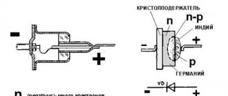
Diode rectifier circuit. Design and operation of a rectifying diode. Diode bridge. Diode bridge circuit This is a so-called single-phase rectifier bridge, one of several types of rectifiers that are actively used in electronics. Ask, I'm in touch!
Diode bridge operation
The operating principle of the diode bridge is as follows. Its input, indicated by an alternating symbol, is supplied with alternating current with changing polarity. The frequency of changes, as a rule, coincides with the frequency in the electrical network. At the output, where the positive and negative terminals are located, a current of exclusively one polarity is obtained.
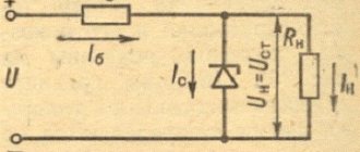
In urban conditions, the voltage in the network, as a rule, remains constant, but protecting the apartment from voltage surges becomes important. Here it’s time to remember the wonders of electronics, since “iron-wire” electrical engineering does not know effective, simple and cheap ways to smooth them out.
Ask around at electrical and radio stores for a surge protector; they are also called “protective barriers”. You can see what this looks like in the illustration. Modern devices of this type are relatively inexpensive, compact, easy to connect and do not require maintenance during operation.
What kind of lighting do you prefer?
Built-in Chandelier
But don’t think about the autotransformer at the dacha - the protective barrier only eliminates voltage surges; It cannot keep the voltage in the socket all the time at a stably low voltage. Supercapacitors are used as energy storage devices in such devices, and although they are “super”, they are still not electric generators.
To obtain a constant voltage from an alternating voltage means to rectify it.
To rectify, you need to make sure that the current can only flow in one direction.
An element that allows current to flow in only one direction is called a diode.
In the diagrams the diode is designated as follows
If you use one diode for rectification, the voltage across the load will turn out to be pulsating.
However, this voltage can already be used to power some low-power DC devices. There is a constant component to this pulsating voltage.
If the alternating voltage is, for example, 10 Volts, then the direct component of the rectified voltage will be 4.5 Volts.
Not enough, for some cases it’s normal, but in our case it’s not enough.
Expert opinion
It-Technology, Electrical power and electronics specialist
Ask questions to the “Specialist for modernization of energy generation systems”
Simple calculation of a rectifier with a network transformer Based on this circuit, it is possible to construct 12 and 24 pulse rectification circuits that use serial and parallel connection of circuits with different combinations of star or delta connections of the secondary windings of the transformer. Ask, I'm in touch!
Basic rectification schemes and their comparative characteristics.
Amateur radio and household radio-electronic equipment is powered only from a single-phase alternating current network. Therefore, single-phase rectification circuits are discussed below.
Basic single-phase voltage rectification circuits: half-wave, full-wave with midpoint, full-wave bridge, voltage multiplier circuit. In practice, complex rectification circuits are also used, formed from two or more simple circuits by combining them. It is advisable to use combined rectification circuits only with a constant load across all output circuits; otherwise, mutual influence of the power supply output channels will be observed.
Half-wave rectification circuit
Single-phase half-wave rectification circuit
Can work both without an input transformer and with a transformer. Current flows through the diode VD only when the polarity of the corresponding half-cycle of the mains voltage will cause the diode to open. The diode current at any time is simultaneously the current of the secondary winding of the transformer and the load current. With an active load, it takes the form of unipolar pulses with a duration equal to half the network period. During the other half-cycle of the supply voltage Uc, the diode VD is in the closed state. When designing a transformer for half-wave rectification circuits, the magnetization of the magnetic core should be taken into account, therefore the overall design power of the transformer should be increased to the value Pr = (3.36...3.5) Po.
Single-phase half-wave rectification circuit
The advantage of the circuit is its simplicity, minimum number of valves.
The disadvantages of a half-wave rectification circuit are the large ripple value of the rectified voltage and the low ripple frequency, equal to the network frequency; poor transformer use; high reverse voltage on the diode (3.14 times the rectified voltage); large current pulse through the diode.
A half-wave rectification circuit is used for low output power (1...3 W) and low requirements for rectified voltage ripple. Most often, such a rectification circuit is used in combination with a single-ended voltage converter and a capacitive filter to convert a low-voltage DC supply voltage to a high-voltage one.
Full-wave rectification circuit with midpoint
Single-phase full-wave rectification circuit with midpoint
is a combination of two parallel-connected half-wave circuits operating alternately on one common load resistance. The circuit can operate from an alternating current network only if there is an input transformer that has a tap from the center point in the secondary winding. The voltage Uc supplied to the primary winding is transformed into secondary ones in such a way that one of them (for example, U'v) is opening for diode VD1, and the other (U''v) is closing for diode VD2. A current pulse similar to the pulse of a half-wave rectification circuit flows through the diode VD1 and the load resistance Rn during half the period of the mains voltage. In the next half-cycle, the polarity of the voltage on the half-windings is reversed, diode VD1 closes, and VD2 opens. In this case, the current pulse will flow through the diode VD2 and the load resistance Rн, that is, the current through the load flows during each half-cycle in one direction.
Single-phase full-wave rectification circuit with a midpoint
Since the currents in the secondary half-windings of the transformer flow alternately in opposite directions, there is no magnetization of the magnetic circuit.
The ripple frequency of the rectified voltage is equal to twice the network frequency.
A full-wave rectification circuit with a midpoint has a number of advantages over a single-half-wave rectification circuit: with the same output power, the dimensions and weight of the transformer are smaller (due to the absence of magnetization); the amplitude of the current through the rectifier diodes is half as large; the ripple frequency of the rectified voltage is twice as high. Compared to a bridge, a full-wave rectification circuit with a midpoint has a smaller number of diodes in the arm and, accordingly, a higher efficiency. Both diodes can be installed on a common radiator without electrical insulation.
The disadvantages of the circuit are the presence of a transformer at the input; worse use of transformer windings compared to other full-wave rectification circuits (current flows through each half-winding only for half a period); high reverse voltage on diodes; the possibility of ripples appearing at the output of the circuit at the network frequency due to the asymmetry of the arms.
The circuit is universal in application, however, due to the high reverse voltage on the diodes, it is rarely used for rectifying high-voltage voltage.
What types of rectifiers are there?
The construction of devices that rectify alternating current is based on the function of the final unit. If it is only necessary to equalize vibrations, assembly on printed circuit boards is carried out using uncontrolled semiconductor elements - diodes. This is how the simplest leveling elements are built.
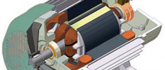
If it is necessary to change the level of power that is transmitted to the receiving equipment, the device is assembled using controlled valves (thyristors). These rectifiers are required to operate some electrically powered motors. By adjusting the supplied voltage, the rotation speed of the rotor changes.
N-phase rectifiers
Such devices have more than 3 phases for current rectification. Other design features vary. A multiphase rectifier can consist of either a full bridge or a quarter and half bridge. Based on the number of inputs and parallelization, they are divided into separate ones, united by stars or rings. In addition, there are sequential types.
Which capacitor to place after the diode bridge - Diode bridge, how to choose the correct capacitor value? — Habr Q&A — ESR Energy
Classification, properties, diagrams, online calculator. Calculation of the capacity of the smoothing capacitor.
Expert opinion
It-Technology, Electrical power and electronics specialist
Ask questions to the “Specialist for modernization of energy generation systems”
Diode Connection Diagram. Modern devices of this type are relatively inexpensive, compact, easy to connect and do not require maintenance during operation. Ask, I'm in touch!
Operation of a rectifier on a load with capacitive response.
Basically, radio amateurs use in their practical activities rectifiers with smoothing filters starting with a capacitor (capacitor), that is, a load with a capacitive response. There is no point in rewriting textbooks; for those interested, the list of references is at the end of the article. I’ll just briefly outline here the basic circuits of rectifiers used by radio amateurs, their features and approximate electrical characteristics, and how they affect the overall power of the transformer.
Half-wave rectifier.
Let's start as usual with a half-wave rectifier.
In such a rectifier, the filter capacitor is charged to the amplitude value of the voltage of the secondary winding (in the absence of load). That is, if the secondary voltage is 10 Volts, then the capacitor will charge to 10x1.41 = 14.1 Volts (this is without a voltage drop across the diode). Advantages of a rectifier;
Simplicity of the circuit, only one valve (diode, kenotron) is used.
Flaws;
Greater dependence of the output voltage on the load current, lower ripple frequency compared to other circuits, which requires the use of capacitors with twice the capacity, poor use of the transformer (low efficiency), and forced magnetization of the core.
When the valve breaks down, alternating voltage is supplied to the capacitor, which leads to its failure and explosion. Features of the scheme;
Used by radio amateurs to power low-current circuits. The reverse voltage in this circuit applied to the valve is approximately three times greater than the voltage of the secondary winding (more precisely 2.82 times), why this happens - try to determine for yourself. That is, if your secondary has a voltage of 100-110 Volts, then the diode must be set to a reverse voltage of at least 400 Volts; it can break through at 300 Volts. The average current through the valve here corresponds to the load current, and the effective value of the current through the valve is twice the load current.
The secondary winding for a half-wave rectifier is selected to be 1.8 -1.9 times higher in current (preferably 2 times) than the load current consumption. To the total calculated power of the transformer, if there are other windings, add the power of this load of yours multiplied by 2.
Full-wave rectifier.
A full-wave rectifier has much better parameters than a half-wave rectifier. The output voltage of this rectifier (capacitor voltage) is 1.41 times higher than the secondary winding voltage (half). This is when there is no load. Advantages of a rectifier;
Small number of valves used (2).
The average value of the current through the valve is almost two times less than the load current. The ripple level of this circuit is 2 times less compared to a half-wave rectification circuit. The capacitance of the capacitor, with the same ripple coefficient as the half-wave circuit, can be 2 times less. There is no forced magnetization of the core, but this depends on the design of the transformer and the method of winding the windings, which will be discussed below. Flaws;
The transformer has a complex design, the secondary winding consists of two halves, hence the inefficient use of copper.
The reverse voltage per valve here is also 2.82 times greater than the voltage (half) of the secondary winding. Poor use of the transformer, since the total calculated power of the entire secondary winding turns out to be 2.2 times the power consumed by the load. Features of the scheme;
Since in one period, in this circuit, both halves of the secondary winding work in turn, and accordingly, the valves (diodes) also work in turn, the average value of the current through one valve (per period) here is almost two times less than the load current . That is, for example, if you put diodes with a permissible constant current of 5 Amps in this circuit, then you can remove 7-8 Amps from this rectifier without much risk of failure of the diodes, naturally providing them with the necessary cooling. The effective current through the valve and the secondary winding here will be 1.1 times greater than the load current. The wire for the secondary winding in this circuit can be chosen 30-40% less in current (cross-section) than the load current, since the halves of the secondary winding also work in turn and the average value of the secondary winding current is less than the load current. But it is better, if the dimensions of the transformer and capabilities allow, to wind the secondary with a wire of the appropriate cross-section with the load current.
About the forced magnetization of the core. If the transformer core is W-shaped, armored, and all the windings are placed on one frame, then there will be no forced magnetization of the core. If the core of the transformer is rod-based and the design of the transformer includes two frames on which the windings are placed, and the network winding consists of two halves placed on different rods (TS-180, TS250), then the secondary winding in such transformers must be performed as follows; Each half of the secondary winding is divided in half again and wound on different rods, then everything is connected in series, first quarters of one half, then the other. As below in the picture. Otherwise there will be magnetization of the core.
Since kenotrons have high internal resistance, when choosing a kenotron rectifier circuit, the voltage of the secondary winding (half) is selected on average by about 10-15% less than the planned output voltage of the rectifier. It also depends on the load current. The higher the load current, the smaller the difference should be. Also remember that in all rectifiers, both with kenotrons and with diodes, the filter capacitors, when there is no load, are always charged to the amplitude voltage of the secondary winding (UC = U2 x 1.41). Take this into account when choosing the voltage of the filter capacitors.
How can we roughly determine here how much power will be added to the total power of the transformer? Without delving deeply into the theory, since there are a lot of factors that depend on each other, you can do the following;
Knowing the calculated load current, we multiply it by 1.7 (circuit with kenotrons), or by 1.6 (circuit with diodes), then multiply the result by the load voltage. This will be the approximate result of the received power, which will be added to the total power of the transformer. There won't be a big mistake here.
Bridge rectifier.
A bridge rectifier, like a full-wave rectifier, has much better parameters than a half-wave rectifier and slightly better efficiency than a full-wave rectifier. Therefore, this is the most common scheme. Advantages of a rectifier;
The average value of the current through the valve is almost two times less than the load current.
The ripple level of this circuit is 2 times less compared to a half-wave rectification circuit. The capacitance of the capacitor, with the same ripple coefficient as the half-wave circuit, can be 2 times less. There is no forced magnetization of the core. Only one secondary winding is used. Flaws;
Poor use of a transformer, since it is necessary to increase the calculated power of the secondary winding by the value of the amplitude value of the voltage of the secondary winding, i.e.
1.41 times. An increased number of valves used (4) and the need to shunt them with resistors to equalize the reverse voltage on each of them. Although this is no longer so relevant given the modern quality of their performance. The voltage drop is also twice as large compared to other circuits, since the rectified current passes through two valves in series. But this is noticeable only at low output voltage and high load currents. Features of the scheme;
In this circuit, just as in the full-wave circuit, the average value of the current through one valve (per period) is almost two times less than the load current. That is, you can also use diodes with a lower operating current (30-40%) than the load current. But the effective current of the secondary winding will always be higher than the load current, at least by 1.41. Therefore, the wire for the secondary winding in this circuit must be selected 1.5 times larger in current (cross-section) than the load current. Why, because the rectifier will always charge the filter capacitor to the amplitude value of the voltage of the secondary winding, and the power is calculated from the value of this voltage. And since, according to the law of conservation of energy, it does not disappear anywhere, the secondary winding has no choice but to constantly make up for this difference. That is, for example, our secondary winding has a voltage of 14 Volts. The filter capacitor will have a voltage of about 20 volts. We loaded it with a current of 0.5 Amperes. The power turned out to be 10 W. This means that the secondary should deliver 10 W, and with an output voltage of 14 Volts it will be a current of approximately 0.71 Amperes, that is, 1.41 times more than the load current.
The secondary winding in the bridge rectifier circuit will always supply energy to charge the capacitor up to the amplitude voltage value, and the load will discharge it. That is, it is like a step-up converter, where the low-voltage part is the secondary winding, and the high-voltage part is the filter capacitor. Therefore, the secondary winding current will always be higher than the load current by this voltage difference, that is, at least 1.41 times.
For example, you found a transformer with an output voltage of 24 Volts and a load current of 5 Amps (120 W). We assembled a linear adjustable power supply, connected it to a 12 Volt load and a current consumption of 5 Amps (60 W). It seems like everything should be fine. We drove for half an hour or an hour, there was a smell of burning, we touched the transformer and got burned. How so?
Let's check what we had with the transformer; The load current is 5 Amps, the voltage on the filter capacitor in XX mode will be 24x1.41 = 33.84 Volts. The power consumed by the load will be 33.84x5 = 169.2 W, and this does not depend on the output voltage of your power supply, at least 5 Volts, at least 25. The rest of the power will simply be lost on the regulating transistor. And it turns out that within an hour our trance delivered power to the load of 170 W!!!, although its power was 120.
Conclusion; For a bridge rectifier circuit, the cross-section of the secondary winding wire must be selected at 50% or 1.5 times greater than the planned load current to ensure normal operating conditions of the transformer, or choose a transformer for your design with a secondary winding current higher than planned by the same amount, so as the load current on the transformers is indicated for a resistive load.
Well, accordingly, the power of the secondary winding is calculated as follows: We multiply the load current by the voltage of the secondary winding and multiply the resulting result by 1.5.
Classification by purpose and device
AC rectifiers are divided into several different types, depending on the characteristics, the use of alternating current periods, circuits, the number of phases and the type of transmitting element. In general, the classification is as follows:
- By the number of periods involved in the work (one- and two-half-wave, as well as with full and incomplete use of the wave);
- By type, devices are divided into those that include an electronic bridge, voltage multipliers, with or without transformers;
- Based on the number of phases, they are divided into single-phase, two-phase, three-phase and N-phase;
- According to the type of device that transmits a sine wave, they are divided into semiconductor diode and thyristor, mechanical and vacuum, mercury;
- Based on the type of transmitted waves, they are divided into pulsed, analog and digital.
Useful tips Connection diagrams Principles of operation of devices Main concepts Meters from Energomer Precautions Incandescent lamps Video instructions for the master Testing with a multimeter
Three phase rectifier
We looked at various implementations of single-phase full-wave converters, but similar devices are also used for three-phase sources. Below, as an example, a device created according to Larionov’s scheme is shown.
An example of the implementation of a Larionov circuit Oscillogram at the output of a Larionov circuit
As the graph above shows, the implementation of a bridge circuit between pairs of phases allows for minor ripples to be obtained at the output. Thanks to this, the filter capacity can be significantly reduced, or even dispensed with.
Half wave rectifier
The rectifier circuit with a capacitor is also considered one of the simplest. It looks like this:
As can be seen in the diagram, an alternating electric current rectifier with a capacitor is also equipped with a transformer that allows it to obtain the desired voltage. At this stage it remains variable, but changes amplitude. The rectifying action is based on the operation of a diode and a capacitor. Only the positive half-cycles of the sinusoid reach the capacitor plates, since the negative ones do not pass through the diode.
The top graph shows the sine wave of voltage entering the rectifier in the diagram shown. The lower one shows what this voltage will be as a result of passing through the diode.
The charge on the capacitor plates increases with increasing voltage. When it decreases to zero, it begins to drain, compensating for the jumps. The output receives a constant voltage. The circuit uses an electrolytic capacitor with a large capacity for this purpose. It is believed that the best converters for household equipment should have a capacity of at least 2200 microfarads.