The conduction of electricity must be carried out in compliance with the rules on which the full functioning of the network depends.
The power cable can be laid over poles or laid in the ground. The last option is considered the most practical, safe and affordable.
But first you should perform calculations of the trenches that will be dug under the cable. Their sizes are determined taking into account the type of wire used.
In any case, many nuances and features must be observed. We will talk about the types of trenches for laying cables in the article.
The importance of size
Underground installation is a popular method of wiring electrical networks . It has a simple circuit, high practicality and safety. But the main thing is that the wires are always underground, which also protects them from vandalism.
It is first necessary to calculate the dimensions of the trenches that will be used for laying wires. This stage should be taken responsibly, because the normal operation of the entire system depends on it.
Width, depth, length depends on the type and size of wire used. If the hole is small and narrow, this may negatively affect the operation of the power transmission network.
Nuances and recommendations
Before starting installation work, it is recommended to study the following nuances and recommendations:
It is worth checking whether the route intersects with utility networks. All necessary data can be obtained after studying the geological basis of the route being laid;- It is important that there are no communication networks at the installation site, otherwise they can be damaged during the digging process;
- Do not forget that the depth depends on the type of terrain in which it will pass;
- If the installation is planned under a highway, then the depth must be at least 1.25 meters;
- If the cable is installed under the lawn, you can dig a hole up to 90 cm deep.
During digging, it is worth taking into account important conditions; it is advisable that no utility lines run underground, otherwise they can be damaged. When calculating the dimensions of the pit, it is necessary to take into account the size of the wires, their number, the use of a protective sheath, the type of terrain, and the type of soil.
Start of excavation work
Once this method of laying the cable for street lighting has been chosen, you should not immediately start digging a trench. Before starting direct excavation work, you need to obtain all the necessary permits, as well as approve the project, which must contain all measurements and parameters for the trench and other aspects of the work.
Note! Obtaining permits and approving the project is necessary, among other things, in order to avoid the situation of damage to communications already existing in the ground when digging a trench.
Cable trench
To go through all the organizations at once and get the desired permit, you need to study the geological basis and add your power system for street lighting into it. After this, to create a trench in accordance with all the rules and regulations, it is necessary to carry out the following manipulations:
- measure the territory of the site at the place of work;
- Next, mark the future trench. To do this, you should use a special device - a level. It will also help determine the exact location of the lighting poles based on the previously created project;
- According to the markings, dig a trench in the ground.
At this point, the stage of creating the trench ends and you can begin the actual laying, according to the created project.
Depth and width
When laying underground, trenches are made along the entire route without breaks. It is first necessary to calculate the depth and width of the hole.
At what depth should the cable be located? The standard depth is considered to be 70-90 cm . If you can’t bury yourself to this level, you can reduce it, but it’s better to lay the wires in pipes or in a protective sheath.
Corrugated hose or special pipes can be used as a shell, the outer surface of which is made of polypropylene with a rigid structure, and the inner area is made of soft polyethylene.
As stated above, depth depends on the type of terrain . In areas with lawns, its indicator can be standard - no more than 90 cm. But in areas under road surfaces, it is better to dig deeper so that the road does not fail in the future.
On normal soil, the depth should be at least 0.7 meters. If unfavorable conditions are observed, for example, the soil is loamy or highly unstable, then the depth can reach up to 1.3 meters.
In addition to depth, it is worth calculating the width correctly. For one cable it should be within 25-30 cm. If two or more lines are laid, then there should be a distance of 10 cm between them. There should be a distance of at least 15 cm from the cables to the wall.
Depth determination depending on power
When calculating trench depth, it is recommended to take into account power indicators. All parameters are shown in the table below:
| Power | Depth indicator |
| At entrances to structures, if there is an intersection with underground structures | 50 cm |
| 20-35 kV | 70 cm |
| From 35 to 110 kV, at all street intersections, on driveways, installation in areas with arable soil | 1 meter |
| From 110 kV and more (oil-filled lines) | 1.5 meters |
Energy site
Armored and unarmored cables indoors and outdoors in places where mechanical damage is possible (movement of vehicles, loads and machinery, accessibility for unqualified personnel) must be protected to a safe height, but not less than 2 m from the ground or floor level and at a depth of 0 .3 m in the ground. (SNiP 3.05.06-85 “Electrical devices” clause 3.63.)PUE clause 2.3.15 cables (including armored ones) located in places where mechanical damage is possible (movement of vehicles, machinery and cargo, accessibility for unauthorized persons) d.b. protected in height by 2 m from the floor or ground level and by 0.3 m in the ground
PUE
2.1.52. Open laying of unprotected insulated wires directly on bases, on rollers, insulators, on cables and trays should be carried out:
1. For voltages above 42 V in rooms without increased danger and for voltages up to 42 V in any rooms - at a height of at least 2 m from the floor or service area.
2. For voltages above 42 V in high-risk and especially dangerous areas - at a height of at least 2.5 m from the floor or service area.
These requirements do not apply to descents to switches, sockets, starting devices, panels, lamps installed on the wall.
In industrial premises, descents of unprotected wires to switches, sockets, devices, panels, etc. must be protected from mechanical influences to a height of at least 1.5 m from the floor or service area.
In domestic premises of industrial enterprises, in residential and public buildings, the specified slopes may not be protected from mechanical influences.
In rooms accessible only to specially trained personnel, the height of openly laid unprotected insulated wires is not standardized.
GOST R 50571.5.52-2011 Low-voltage electrical installations. Part 5-52. Selection and installation of electrical equipment. Electrical wiring
522.6 Shock (AG) 522.6.1 Electrical wiring shall be selected and installed to minimize damage from mechanical external forces such as shock, foreign body penetration, or compression during installation, operation, or maintenance. 522.6.2 In fixed installations where moderate severity (AG2) or high severity (AG3) impacts may occur, protection shall be provided by: — the mechanical characteristics of the electrical wiring; or - the choice of its location; or - by additional local or general mechanical protection; or - a combination of the above methods. Notes 1. For example, areas under the floor in forklift operating areas. 2. Additional mechanical protection can be achieved by using appropriate cable fittings (ducts, pipes). 522.6.3 Cable installed under the floor or above the ceiling shall be installed in such a way as to prevent damage from contact with the floor or ceiling and/or elements for their fixation. 522.6.4 The level of protection of electrical equipment shall be maintained after cables and conductors are connected. 522.8 Other Mechanical Impacts (AJ) 522.8.1 Electrical wiring shall be selected and installed in such a manner as to prevent damage to the sheath and insulation of cables or insulated conductors and their connections during installation and operation. The use of silicone lubricants for tightening and installing cables and wires in pipes, placement in cable and special cable boxes, cable trays and cable ladders is not allowed. 522.8.2 For concealed electrical wiring in building structures, pipes or special conduit systems shall be completely installed for each circuit before insulated wires or cables are tightened therein. 522.8.3 The bend radius of wires and cables must be such that they do not cause damage when tightened. 522.8.4 When laying wires and cables on supporting structures with supports, the distance between the supports must be such as to prevent damage to the wires and cables from their own weight. NOTE Electrodynamic forces arising from short circuits should be taken into account for single-core cables with a cross-sectional area greater than 50 mm. 522.8.5 For locations where electrical wiring is subject to constant tension (for example, tensile force on vertical sections of the route from its own weight), the appropriate type of cable or conductor of the required cross-section and installation method should be selected in order to prevent damage to the conductors and cables from their own weight. 522.8.6 Electrical wiring that involves the tightening and pulling of wires or cables shall be provided with appropriate means of access to perform such an operation. 522.8.7 Electrical wiring in floors shall be adequately protected to prevent damage during normal use of the floor. Electrical wiring that is rigidly fixed and embedded in walls must be located horizontally, vertically or parallel to the edges of the walls of the room. 522.8.8 Electrical wiring laid in building structures without fastening may be located along the shortest path. Electrical wiring in ceilings may be located along the shortest path. 522.8.9 Electrical wiring shall be installed to avoid the application of mechanical forces to conductors and connections. 522.8.10 Cables, pipes or special conduits installed in the ground shall be provided with protection from mechanical damage or shall be installed underground at a depth that minimizes the risk of such damage. Cables laid underground must be marked with cable covers or suitable warning tape. Pipes and special ducts laid underground must be identified accordingly. Notes 1. Requirements for underground pipes are given in IEC 61386-24. 2. Mechanical protection may be provided by using pipes buried in the ground in accordance with IEC 61386-24, or by using armored cables or other suitable methods such as covering with slabs. 522.8.11 Cable shelves and their outer enclosures shall not have sharp edges that could damage cables or insulated conductors. 522.8.12 Cables and conductors shall not be damaged by means of securing. 522.8.13 Cables, busbars and other electrical conductors that pass through expansion joints shall be selected and installed so that their movement will not cause damage to the electrical equipment, such as the use of flexible wiring. 522.8.14 If electrical wiring passes through a partition, it must be protected from mechanical damage, for example, by a metal sheath or the use of armored cables, or by using a pipe or O-ring. NOTE Electrical wiring shall not be permitted to pass through a member of a building structure that is intended to carry a load unless the integrity of the load-carrying member cannot be guaranteed after the load has been applied.
Distance between cables
When installing a line in one trench, it is allowed to place no more than 6 cables. But they must be laid at a certain distance so that there is no short circuit or failure of the entire electrical line. There must be a gap of at least 10 cm between the wires.
But do not forget about the cable power indicator , the distance between the lines during parallel horizontal installation depends on it:
Between power wires with a power rating of up to 10 kV there should be no more than 10 cm;- Between 20-35 kV lines the gap should be 25 cm;
- The distance between cables used in production, between power wires and communication lines should be 50 cm;
- Between oil-filled wires with a power of 110-220 kV and other communications there should be 50 cm or more.
Oil-filled cable lines are separated from each other by reinforced concrete slabs, which are installed on the ribs.
Places where it is beneficial to use the method
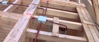
Electrical wiring on the floor is convenient in houses that have not yet undergone any renovation. Such buildings include newly erected new buildings, where, as a rule, only pre-finishing has been done. You will not have to violate the integrity of the walls; the cable can be laid in a place convenient for you in the floor, and the necessary wiring can be made from it to switches and sockets.
Installation under the floor will also be a profitable solution for a wooden house. In this case, wiring disadvantages associated with difficult access will disappear. For a wooden house, this solution is quite relevant, since running cable ducts along the walls will significantly affect the interior of the rooms, and retro-style wiring will cost much more than modern wiring.
By placing the cable under the floor, you will not only hide all the wires and make the wiring convenient, but if necessary, you can easily pull it out from under the boards and make repairs.
Distance from other engineering networks
Laying lines in trenches next to other utility networks should be carried out at a certain distance:
- If there is a water supply, drainage, or sewerage system parallel to the highway, then the distance between these objects should be no more than 1 meter;
- If a gas pipe with a pressure indicator from 0.0049 to 0.0058 MPa is installed in parallel, then the distance should be at least 1 meter, but if the pipe pressure is higher than 0.0058 MPa, then the distance will be at least 2 meters;
- The distance between the line and the heating main is 2 meters;
- If the power transmission network is laid along railways, then it is better to install it in the exclusion zone;
- If the power line is laid along tram tracks, then it should be built at a distance of 2.75 meters;
- If in forest plantations, park areas, then there should be a gap of about 2 meters between trees and cables. This figure can be reduced, but it must be at least 0.45 meters, and the wires must be laid in pipes;
- If the electrical network is laid along highways of categories I and II, then it is better to install the cable from the outer area of the sole or a ditch from the edge of the road surface at a distance of at least 1 meter. The distance between the line and the curb stone is 1.5 meters.
If the electric wire is laid near the foundations of buildings, then it is better to install the line at a distance of 60 cm. From the power transmission line supports with a voltage of 1 kV and below to the power line there should be at least 2 meters, and to the grounding - 5 meters.
The final stage of installation
Once you have ensured that the cable has not been damaged during installation, the trench can be backfilled. All laid communications should be covered with sand. Its layer, as at the bottom of the trench, should be 15 cm. The sand, according to the scheme described above, is first moistened with water and then compacted. After this, the trench is simply filled with soil to half the remaining depth. Now you need to place a special signal tape in it. It will serve as an additional signal that a cable is laid below.
Laying warning tape in a trench
It is especially important to lay such a tape when laying it around the territory of a private house. It will protect the gasket from accidental excavations, which are most possible in this situation. After this, the remaining soil is poured into the trench and compacted.
Dimensions table
Table - dimensions of trenches, volumes of earthworks:
| Trench type | Width in mm | Height in mm | Volume of excavation work per 100 m of trench, m3 | Volume of fine sifted earth or sand per 100 meters of trench, m3 | Laying depth | |
| Digging a trench | backfilling | |||||
| T-1 | 200 | 900 | 18 | 12 | 6 | 700 |
| T-2 | 300 | 27 | 18 | 3 | ||
| T-3 | 400 | 36 | 24 | 12 | ||
| T-4 | 500 | 45 | 30 | 15 | ||
| T-5 | 600 | 54 | 36 | 18 | ||
| T-6 | 700 | 63 | 42 | 21 | ||
| T-7 | 800 | 72 | 48 | 24 | ||
| T-8 | 900 | 81 | 54 | 27 | ||
| T-9 | 1000 | 90 | 60 | 30 | ||
| T-10 | 300 | 1250 | 37,5 | 28,5 | 9 | 900 |
| T-11 | 500 | 62,5 | 47,5 | 15 | ||
| T-12 | 600 | 75 | 57 | 18 | ||
| T-13 | 800 | 100 | 78,6 | 24 | ||
| T-14 | 900 | 112 | 85 | 27 | ||
| T-15 | 1000 | 125 | 95 | 30 | ||
Table - selection of the type of trench in accordance with the number of cables laid in it up to 10 kV:
| Trench type | Number of cables, pcs. | |||||||
| with cable diameter, mm | ||||||||
| To 10 | Up to 20 | Up to 30 | Up to 40 | Up to 50 | Up to 60 | Up to 70 | Up to 80 | |
| T-1 | 1;2 | 1 | 1 | 1 | 1 | 1 | 1 | 1 |
| T-2 | 2 | 2 | 2 | 2 | 2 | |||
| T-10 | ||||||||
| T-3 | 3 | 3 | 3 | 3 | 2 | 2 | ||
| T-4 | 4 | 4 | 4 | 3 | 3 | 3 | ||
| T-11 | ||||||||
| T-5 | 5 | 5 | 4 | 4 | 3 | |||
| T-12 | ||||||||
| T-6 | 6 | 6 | 5 | 5 | 4 | |||
| T-7 | 6 | 5 | 5 | 4 | 4 | |||
| T-13 | ||||||||
| T-8 | 6 | 6 | 5 | 5 | ||||
| T-14 | ||||||||
| T-9 | 6 | 6 | ||||||
| T-15 | ||||||||
Important and useful information about laying cables in a trench is in this section.
What to rely on in theory
Everything related to the creation of lighting, especially the street plan, is spelled out in the appropriate documentation. These include:
- SNiP, which stands for “building codes and regulations”. This documentation provides standards for the level of illumination, as well as the requirements for organizing external and internal lighting;
- SanPin. This abbreviation stands for “sanitary norms and rules”. This document serves as a supplement to SNiP and comes to the fore only when it concerns public premises, especially educational ones;
- GOST These documents list all the requirements that lighting and other devices used in certain situations must meet.
Laying cables in the ground to create street lighting is a labor-intensive process that ultimately must:
- provide high-quality power to outdoor lighting fixtures;
- create conditions for the safe movement of people along the ground in which the cable is laid;
- prevent moisture from penetrating inside the electrical component of the wiring. This situation carries the risk of a short circuit, which can lead to a fire.
In addition, it should be remembered that violation of the technology for laying cables for outdoor lighting in the ground can lead to electric shock to a person. Therefore, in order to avoid negative consequences for yourself and others, these installation works should be carried out only after detailed familiarization with all special documentation. Below are the requirements, standards and work procedures specified in this documentation. Everything necessary for the work can be found in the relevant sections and subsections. Here we will consider the main and most important aspects of laying for understanding.


