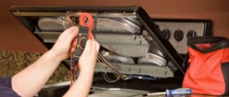
In modern electrical appliances, fuses are found everywhere, or, to put it scientifically, fuses.
They protect the network and the device itself from short circuits or overload. The design of fuse links is very diverse, as are the sizes. The rated currents and voltages for which fuses are issued correspond to standard values. Its overall dimensions, namely length, depend on the rated voltage of the fuse; the higher the rated voltage of the fuse, the greater the distance between the contacts. The rated current is determined by the cross-section of the wire inside the fuse. Although self-resetting electrical fuses can now be found in more expensive devices, most devices are still equipped with conventional fuses.
General calculation rules
To correctly size fuses, the rated voltage must be taken into account. This value must be such that the fuse breaks the electrical circuit. The main indicator is the minimum expected voltage for the base and fuse.
Another important indicator that must be taken into account when calculating is the cut-off voltage. This parameter represents the instantaneous voltage value that appears after the fuse or fuse itself has burned out. As a rule, the maximum value of this voltage is taken into account.
In addition, the melting current is taken into account, on which the diameter of the wire installed inside depends. When calculating a fuse, this indicator has its own value for each metal and is selected using a table or calculator. The material and dimensions of the inserts must provide the required protective properties. The insert length should not be excessive as this will affect arc extinction and overall temperature performance.
The load power rating is usually stated on the product label. Based on this parameter, the rated current of the fuse is calculated using the formula: Inom = Pmax / U, where Inom is the rated protection current, Pmax is the maximum load power, and U is the supply voltage.
Calculation of wire cross-section
Strictly speaking, the concept of “thickness” for a wire is used colloquially, and the more scientific terms are diameter and cross-sectional area. In practice, the thickness of the wire is always characterized by its cross-sectional area.
In practice, calculating the wire cross-section is very simple. Knowing the diameter (for example, by measuring it with a caliper), you can easily calculate the cross-sectional area using the formula
S = π (D/2)2 , where
- S – wire cross-sectional area, mm2
- π – 3,14
- D – diameter of the conductor of the wire, mm. It can be measured, for example, with a caliper.
The formula for the cross-sectional area of a wire can be written in a more convenient form: S = 0.8 D² .
Amendment. Frankly, 0.8 is a rounded factor. A more accurate formula: π (1/2)2 = π / 4 = 0.785. Thanks to attentive readers
Let's consider only copper wire , since it is used in 90% of electrical wiring and electrical installations. The advantages of copper wires over aluminum wires are ease of installation, durability, and reduced thickness (at the same current).
But with an increase in diameter (sectional area), the high price of copper wire eats up all its advantages, so aluminum is mainly used where the current exceeds 50 Amperes. In this case, a cable with an aluminum core of 10 mm2 or thicker is used.
The cross-sectional area of the wires is measured in square millimeters. The most common cross-sectional areas in practice (in household electrics): 0.75 (prohibited in fixed wiring), 1.5, 2.5, 4 mm2
There is another unit for measuring the cross-sectional area (thickness) of a wire, used mainly in the USA - the AWG system . On Samelektrika there is a table of wire cross-sections according to the AWG system and conversion from AWG to mm2.
Regarding the selection of wires, I usually use catalogs from online stores, here is an example of copper. They have the largest selection I've ever seen. It’s also good that everything is described in detail - composition, applications, etc.
I also recommend reading my article about choosing a wire cross-section for direct current; there are a lot of theoretical calculations and discussions about voltage drop, wire resistance for different cross-sections, and which cross-section to choose is optimal for different permissible voltage drops.
And another article - Voltage drop on long three-phase cable lines. a real example of an object is given, formulas and recommendations are given on how to reduce losses. Wire losses are directly proportional to current and length. And inversely proportional to resistance.
When choosing the cross-sectional area of the wires, you should be guided by three basic principles.
- The cross-sectional area of the wire (in other words, its thickness) must be sufficient for the passage of electric current through it. Sufficient - this means that when the maximum possible current in this case passes, the heating of the wire will be acceptable (as a rule, no more than 60 0C)
- The cross-section of the wire must be sufficient so that the voltage drop across it does not exceed the permissible value. This is especially true for long cable lines (tens and hundreds of meters) and high currents.
- The thickness of the wire and its protective insulation must ensure its mechanical strength, and therefore reliability.
For example, to power a chandelier in the living room, light bulbs with a total power consumption of 100 W (current slightly more than 0.5 A) are used. It seems that wires with a cross-sectional area of 0.5 mm2 are quite enough? But what electrician in his right mind would install such a wire in a ceiling slab? In this case, 1.5 mm2 is usually used.
In fact, the choice of wire thickness depends on one parameter - the maximum operating temperature.
If this temperature is exceeded, the wire and the insulation on it will begin to melt and collapse. In other words, the maximum operating current for a wire with a certain cross-section is limited only by its maximum operating temperature. And the time that the wire can work in such conditions. Below is a well-known table of wire cross-sections for selecting the cross-sectional area of copper wires depending on the current. The initial data is the cross-sectional area of the conductor.
Selecting wire diameter and fuse repair
Well, now let’s move on to the main problem of our article – the choice of diameter and the repair itself. Let's start with the first one.
Conductor diameter selection
The diameter of the core in the fuses is clearly calculated. When replacing, it is necessary to install a conductor of the same diameter. Otherwise, the fuse will not perform its function of protecting the electrical network.
- This can be done in several ways. The easiest way is to take the wire size for the fuse, and the table of standard values will allow you to make your choice. To do this, just measure the diameter of the wire.
- The diameter of the wire can be measured with a caliper or even a regular ruler. If the diameter of the fuse wire is too small, measurements can be made as follows. Let's wind the thread around any small object: lighter, pencil, pen.
How to choose power wiring
The power cord must be suitable for the system from which it is powered. If the cable is not thick enough, there will be large losses, that is, “waste”, as this phenomenon is now commonly called. This is due to the fact that the cable has resistance, albeit infinitesimal.
it is really very small, about 0.3 - 0.8 Ohm per km of cable length. But it still exists and at high currents in the line the losses can be noticeable.
Selection of cable cross-section
To select a cable of the required cross-section, you do not need to calculate anything. Obviously, you can set the current consumption, the permissible absorption, for example, the current in the system is 100 A, and the absorption does not exceed 0.5 V, and calculate the required cable cross-section taking into account the length of the line. It's not obligatory. There is an old rule of thumb for choosing power cables, which for simplicity is called "five amps per square":
It is based on the fact that the line length from the source to the users (to the amplifiers) does not exceed 5 m. This is 99% of all cases. What does this rule mean? This is normal for current density. With a current density of five amperes per square millimeter, losses on a cable up to 5 meters long will be no more than 0.5 V. In particular, no more than 0.5, this is an important, maximum, non-operating current.
How to use this rule? Take the amplifier and see what its fuse rating is. If there are many of them, consider the total denomination. If you have several amplifiers and are going to power them with one cable, add their preset values. Let's take the result obtained as the maximum current consumption. A real worker will be significantly smaller. We divide the maximum current by 5 and get the required cable cross-section (“5 A per 1 kV mm).
Next, take the next largest standard cable size. We have an Oris TA-150.4 amplifier with a 100A fuse. Typically, the manufacturer provides a margin of 10-20% when choosing a fuse. Accept maximum current 100A. Divide 100 by 5 to get 20 squares. To power such an amplifier, you will need a cable with a cross-section of at least 20 square mm. We choose the following standard cable cross-section: 25 sq. All. To power the Oris TA-150 amplifier.
4, a cable with a cross-section of 25 square millimeters is needed and sufficient. You can use a cable with a larger cross-section, it will not be worse. Will be better? Practice shows that if you take a cable two or more sizes larger, it will definitely not be better. However, losses in the cable tend to zero.
Using the five amps per square rule, select the required wire size or size larger. It is not recommended to buy a thicker cable.
Prosad doesn't just live by cable. And, for example, also on the fuse.
Fuse selection
A power line fuse is mandatory and must be installed near the power source. In an emergency, it must protect the power supply from short circuits. Whatever happened, the cable was frayed and shorted to ground, or the amp burned out and shorted it somehow. The fuse must blow to prevent the wiring from catching fire.
The principle of operation of the fuse is simple and is based on Ohm's law for a closed circuit.
Where Un is the voltage drop between the elements of the system: on the wiring, firstly, on the amplifier itself, etc.
These are all sorts of sags, but we don't call them voltage drops across the amplifier. The magnitude of the voltage drop on the line depends on the resistance of the system element and is always many times less than the voltage drop on the main link, the amplifier. So far everything is good, the losses on the cable and on the fuse are not significant, everything works. Now let’s imagine that some kind of emergency has occurred. Short circuit in the wiring.
Of all the elements of the system connected to the power source (battery), only the power cord and fuse remained (the amplifier fell out of the system). And all its energy will be dissipated directly on the cable and on the front panel. What will burn first, the filament or the first? For a fuse to blow, the drawdown on it must be much greater. This will work stably. Therefore, you need to select a fuse strictly according to the cable.
Not from current consumption, but from cable cross-section.
The fuse rating is also selected in accordance with the “five amperes per square” rule. Only in the opposite direction. Let's say you need to choose a fuse for a cable with a cross-section of 25 squares, which powers the same Oris TA-150.4 amplifier. Multiplying 25 by 5, we get the required power of 125A. The next highest value is 150A.
If the power wiring is selected according to the described rule, the system operates stably, with a good margin, and in the event of a short circuit, the fuse operates clearly. Losses in cables and fuses are very low. Do not bypass the fuse. This is sometimes done in competitions to reduce drawdown. But in everyday life we don’t need this at all.
Fuse selection
The choice of fuse is determined by the initial data and features of a particular application [1]:
- Rated current . The circuit's current rating determines the fuse's current rating. To protect against unplanned operations, it is recommended to use a current reserve of 25%. For example, if the rated current of the circuit is 7.5 A, then, taking into account the margin, you should select a fuse based on a current value of 10 A.
- Operating temperature also greatly influences the choice of fuse current rating, so additional margin is necessary for proper operation. For example, if 438 series fuses are expected to operate at a temperature of 75°C, then the margin should be about 15% (see Figure 2).
Let's look at an example. Let's say a 438 series fuse must operate at a temperature of 75°C and a rated current of 1.5 A. Obviously, taking into account points 1 and 2, a fuse with a rating of 1.5 A will not be enough for normal operation. The required current rating with a margin is: 1 .5 A/(0.75 × 0.85) ≈ 2.4 A → 2.5 A (closest rating).
- Operating voltage . The fuse voltage rating must be greater than the maximum possible voltage in the circuit.
- Response speed . Based on the response speed, fuses are divided into five types (FF - super-fast, F - fast, M - semi-slow, T - slow, TT - super-slow). The choice of a specific fuse should be made taking into account the ampere-second ratings provided by the manufacturer.
- Maximum short circuit current . To prevent the fuse from melting or exploding, its breaking capacity must be greater than the maximum short-circuit current.
- Requirements for dimensions, standard size and installation method . There is now a wide range of fuses available for surface mounting, through-hole mounting and for mounting in special holders. The choice of a specific series is determined by the characteristics of each specific application.
- Compliance with standards . The use of a particular fuse is permitted only if it is certified and meets the requirements of established standards. In addition to the GOST R IEC 60127 group of standards, there are other standards. For example, to operate in explosive atmospheres, the fuse must comply with the provisions of GOST 31610.11-2014 (IEC 60079-11:2011) “Explosive atmospheres. Part 11. Equipment with type of explosion protection “intrinsically safe electrical circuit “i” (with Amendment)”.
- Resistance to impulse influences . This point should be discussed in more detail.
This data is sufficient to select a fuse operating in a circuit with a constant or variable sinusoidal current load, if this load does not exceed the current rating of the fuse. However, there are many applications in which the load is pulsed. We are talking about starting currents and various transient processes. In such applications, the fuse must be able to withstand momentary current surges in excess of its current rating without tripping.
To determine whether a fuse will trip or not trip when a given number of current pulses occurs, use the Joule integral I2t, which can be calculated manually or using special utilities. Let's consider each method separately.
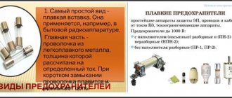
Fuse Types
According to their purpose and design, fuses are of the following types:
- Plug (mainly used to protect cables and electrical devices in cars);
- With low-current inserts to protect electrical appliances with current consumption up to 6 amperes;
- Cork (installed in the screens of residential buildings, designed for protection currents up to 63 amperes);
- Knife type (used in industry to protect networks with current consumption up to 1250 amperes);
- Gas generation;
- Quartz.
The repair technology discussed in the article is intended to restore the plug using low-current inserts, plug and blade fuses.
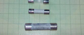
Tubular fuses
A fuse of a tubular design is a glass or ceramic tube, closed at the ends with metal caps, which are connected to each other by a wire of calibrated diameter passing through the inside of the tube. You can see what tubular fuses look like in the photo.
The wire is spot welded or welded to the caps. In fuses designed for very high currents, the cavity inside the tube is often filled with quartz sand.
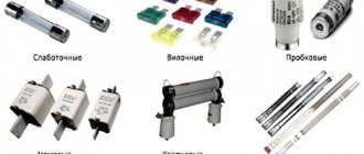
Automotive fuses
Car fuses rarely fail. Usually only in cases where the equipment fails. Very often when light bulbs near the headlights burn out. The fact is that when the filament of the bulb breaks, a galvanic arc is formed, the filament burns out and shortens, the resistance drops sharply, and the current increases many times over.
It happens that when the wipers jam, the car fuse blows. Less often with short circuits in the wiring. In the photo you can see commonly used car blade guards. Below each fuse is indicated its protection current in amperes.
A blown fuse in a car should be replaced with a fuse of the same rating, but you can also fix it by replacing the blown fuse with a copper wire of the appropriate diameter. The voltage of the car's on-board network does not matter. The main thing is the correspondence of the protection current. If it is difficult to determine the size of a blown circuit breaker, you can use color coding.
Color coding of automotive fuses
Protection current, Ampere Body color fuse orange brown red blue yellow transparent green purple blue black
| 5.0 | 7,5 | 10.0 | 15.0 | 20,0 | 25,0 | 30,0 | 40,0 | 60,0 | 70,0 |
Review of Littelfuse fuses
Littelfuse is one of the leaders in the field of fuses. The company's product range includes SMD fuses, fuses with radial and axial leads, as well as fuses of various specialized series and models.
SMD fuses are in demand primarily in low-voltage applications, where compact dimensions play a key role. In addition, they significantly simplify the installation process, since they are soldered together with other SMD components onto a printed circuit board. Additional benefits of SMD fuses include high speed, low resistance, and a wide range of current ratings.
Currently, Littelfuse offers almost forty series of SMD fuses with different characteristics (Figure 14, Table 1):
- with a current rating of 0.62...40 A;
- with voltage ratings up to 600 V;
- with TT, F and FF speed;
- with standard size from 0402;
- with operating temperature range -55…150°C.
Rice. 14. SMD fuses from Littelfuse
Table 1. Characteristics of Littelfuse SMD fuse series
| Type | Name | Ampere-second characteristics | Frame | Current rating, A | Voltage rating, V | Breaking capacity, A | Operating temperature, °C | ||
| TT | F | FF | |||||||
| Ceramic | 437 | – | + | – | 1206 | 0,25…8 | 125/63/32 | 50 | -55…150 |
| 438 | – | + | – | 0603 | 0,25…6 | 32/24 | 50 | ||
| 440 | – | + | – | 1206 | 1,75…8 | 32 | 50 | ||
| 441 | – | + | – | 0603 | 2…6 | 32 | 50 | ||
| 469 | + | – | – | 1206 | 1…8 | 24/32 | 24…63 | ||
| 501 | – | + | – | 1206 | 10, 12, 15, 20 | 32 | 150 | ||
| Thin film | 466 | – | – | + | 1206 | 0,125…5 | 125/63/32 | 50 | -55…90 |
| 429 | – | – | + | 1206 | 7 | 24 | 35 | ||
| 468 | + | – | – | 1206 | 0,5…3 | 63/32 | 35…50 | ||
| 467 | – | – | + | 0603 | 0,25…5 | 32 | 35…50 | ||
| 494 | + | – | – | 0603 | 0,25…5 | 32 | 35…50 | ||
| 435 | – | – | + | 0402 | 0,25…5 | 32 | 35 | ||
| Nano2® Fuse | 448 | – | – | + | 2410 | 0,062…15 | 125/65 | 35…50 | -55…125 |
| 449 | + | – | – | 2410 | 0,375…5 | 125 | 50 | ||
| 451/453 | – | – | + | 2410 | 0,062…15 | 125/65 | 35…50 | ||
| 452/454 | + | – | – | 2410 | 0,375…12 | 125/72 | 50 | ||
| 456 | + | – | – | 4012 | 20, 25, 30, 40 | 125 | 100 | ||
| 458 | – | + | – | 1206 | 1,0…10 | 75/63 | 50 | ||
| 443 | + | – | – | 4012 | 0,5…5 | 250 | 50 | ||
| 464 | – | + | – | 4818 | 0,5…6,3 | 250 | 100 | ||
| 465 | + | – | – | 4818 | 1…6,3 | 250 | 100 | ||
| 462 | + | – | – | 4118 | 0,500…5 | 350 | 100 | -40…80 | |
| 485 | – | + | – | 4818 | 0,500…3,15 | 600 | 100 | -55…125 | |
| Telelink® Fuse | 461 | – | – | – | 4012 | 0,5…2,0 | 600 | 60 | -55…125 |
| 461E | – | – | – | 4012 | 1,25 | 600 | 60 | ||
| OMNI-BLOK® | 154 | – | – | + | * | 0,062…10,0 | 125 | 35…50 | -55…125 |
| 154T | + | – | – | * | 0,375…5 | 125 | 50 | ||
| Fuses with holder | 157 | – | – | + | * | 0,062…10 | 125 | 35…50 | -55…125 |
| 157T | + | – | – | * | 0,375…5 | 125 | 50 | ||
| 159 | – | – | – | 0,5…2 | 600 | 60 | |||
| 160 | + | – | – | * | 0,5…5 | 250 | 50 | ||
| PICO® SMF | 459 | – | – | + | * | 0,062…5 | 125 | 50…300 | -55…125 |
| 460 | + | – | – | * | 0,5…5 | 125 | 50 | ||
| Flat Pak | 202 | – | + | – | * | 0,062…5 | 250 | 50 | -55…125 |
| 203 | + | – | – | * | 0,25…5 | 250 | 50 | ||
| EBF | 446 | – | + | – | * | 2,0…10,0 | 350 | 100 | -40…125 |
| 447 | – | + | – | * | 2,0…10,0 | 350 | 100 | ||
| * – Case of non-standard size. | |||||||||
A series of ceramic SMD fuses are characterized by high temperature stability and are capable of operating at elevated temperatures (up to 150°C). This allows them to be used in industrial electronics and in ultra-compact applications with limited heat dissipation capabilities: servers, printers, scanners, modems, etc.
Thin film SMD fuses are used as secondary protection elements in devices that require compact overall dimensions. In particular, the 435 has a standard size of only 0402. The main applications for this group of fuses will be cell phones, digital cameras, battery assemblies, etc.
Nano2® Fuse fuses feature compact dimensions, a wide range of current ratings of 0.62...40 A and a significant operating temperature range of -55...125°C. Thanks to these advantages, Nano2® Fuse can be used in a wide range of applications from laptops and LCD monitors to servers and industrial equipment.
Telelink® Fuse fuses are designed for use in telecommunications equipment. When combined with SIDACtor® or Greentube from Littlefuse, they provide a complete equipment protection solution that meets GR-1089–Core, TIA-968-A, UL/EN/IEC 60950, ITU K.20 and K recommendations. 21.
OMNI-BLOK fuses are a combination of a fuse and a holder that are soldered onto the board using conventional surface mounting. In the future, the user can independently replace the fuse without the need for soldering.
PICO SMF is a surface mount version of PICO They are distinguished by a wide range of rated currents of 0.62...5 A and high speed.
Flat Pak – fuses with a wide range of rated currents 0.62...5 A, operating voltage up to 250 V AC and two versions: SMD and DIP (through-hole mounting).
EBF is a series of SMD fuses designed for electronic ballast circuits and high-power inverters. There is a version for through-hole mounting with the same overall dimensions.
Littelfuse offers almost three dozen series of fuses with radial leads (Figure 15, Table 2):
- with current rating 0.02...10 A;
- with voltage rating up to 300 V;
- with speed TT, M, F and FF;
- with an operating temperature range up to -55…125°C.
Rice. 15. Littelfuse fuses with radial leads
Table 2. Characteristics of the Littelfuse fuse series with radial leads
| Type | Name | Ampere-second characteristics | Current rating, A | Voltage rating, V | Breaking capacity, A | Operating temperature, °C | |||
| TT | M | F | FF | ||||||
| Micro/TR3 | 262/268/269 | – | – | – | + | 0,002…5 | 125 | 10,000 | -55…125 |
| 272/278 | – | – | – | + | 0,002…5 | 125 | 10,000 | -55…125 | |
| 273/274/279 | – | – | – | + | 0,002…5 | 125 | 10,000 | -55…85 | |
| 303 | – | – | + | – | 0,5…5 | 125 | 50 | –55…70 | |
| TR5 | 370 | – | – | + | – | 0,4…6,3 | 250 | 35…50 | -40…85 |
| 372 | + | – | – | – | 0,4…6,3 | 250 | 35…50 | ||
| 373 | – | – | + | – | 0,5…10 | 250 | 50 | ||
| 374 | + | – | – | – | 0,5…10 | 250 | 50 | ||
| 382 | + | – | – | – | 1…10 | 250 | 100 | ||
| 383 | + | – | – | – | 1…10 | 300 | 50…100 | ||
| TE5 | 369 | + | – | – | – | 1…6,3 | 300 | 50 | -40…85 |
| 385 | + | – | – | – | 0,35…1,5 | 125 | 50 | ||
| 389 | + | – | – | – | 0,6 | 250 | 10 | ||
| 391 | – | – | + | – | 0,125…4 | 65 | 50 | ||
| 392 | + | – | – | – | 0,8…6,3 | 250 | 25…63 | ||
| 395 | – | – | + | – | 0,05…6,3 | 125 | 100 | ||
| 396 | + | – | – | – | 0,05…6,3 | 125 | 100 | ||
| 397 | + | – | – | – | 0,35…1,5 | 125 | 50 | ||
| 398 | – | + | – | – | 0,125…4 | 65 | 50 | ||
| 399 | + | – | – | – | 0,125…4 | 65 | 50 | ||
| 400 | + | – | – | – | 0,5…6,3 | 250 | 130 | ||
| 804 | + | – | – | – | 0,8…6,3 | 250 | 150 | -40…125 | |
| 808 | – | + | – | – | 2…5 | 250 | 100 | -40…85 | |
| TE7 | 807 | + | – | – | – | 0,8…6,3 | 300 | 100 | -40…125 |
The Littelfuse range includes an extensive group of fuses with axial leads (Figure 16, Table 3):
- with current rating 0.1...50 A;
- with voltage rating up to 1000 V;
- with speed TT, M, F and FF;
- with an operating temperature range up to -55…125°C.
Rice. 16. Littelfuse fuses with axial leads
Table 3. Characteristics of Littelfuse fuse series with axial leads
| Type | Name | Ampere-second characteristics | Current rating, A | Voltage rating, V | Breaking capacity, A | Operating temperature, °C | |||
| TT | M | F | FF | ||||||
| PICO/PICO II Axial | 251/253 | – | – | – | + | 0,062…15 | 125 | 300DC/50AC | -55…125 |
| 275 | – | – | – | + | 20…30 | 32 | 300DC/50AC | ||
| 263 | – | – | – | + | 0,062…5 | 250 | 50 | ||
| 471 | + | – | – | – | 0,5…5 | 125 | 50 | ||
| 472 | + | – | – | – | 0,5…5 | 125 | 50 | ||
| 473 | + | – | – | – | 0,375…7 | 125 | 50 | ||
| 265/266/267 | – | – | – | + | 0,062…15 | 125 | 300DC/50AC | ||
| 3.6×10 mm | 874 | – | – | – | + | 0,1…10 | 250 | 50 | -55…125 |
| 875 | + | – | – | – | 0,1…10 | 250 | 50 | ||
| 876 | – | – | – | + | 0,125…5 | 250 | 35–50 | ||
| 877 | + | – | – | – | 2…6,3 | 250 | 35–63 | ||
| 4.5×14.5 mm (2AG) | 208 | – | – | + | – | 0,125…10 | 350 | 100 | -55…125 |
| 209 | + | – | – | – | 0,25…7 | 350 | 100 | ||
| 220 | Special Edition | 0,3…7 | 250/300/350 | 35…100 | |||||
| 2205 | + | – | – | – | 0,25…2,5 | 250 | 35 | ||
| 224/225 | – | – | + | – | 0,375…10 | 250/125 | 35…500 | ||
| 229/230 | + | – | – | – | 0,25…7 | 250/125 | 35…400 | ||
| 5×20 mm | 201P | – | – | – | – | 0,05…1,25 | 250 | 80 | -25…70 |
| 217 | – | – | + | – | 0,032…15 | 250 | 35…150 | -55…125 | |
| 218 | + | – | – | – | 0,032…16 | 250 | 35…100 | ||
| 213 | + | – | – | – | 0,2…6,3 | 250 | 35…63 | ||
| 219XA | + | – | – | – | 0,04…6,3 | 250 | 150 | ||
| 216 | – | – | + | – | 0,05…16 | 250 | 750…1500 | ||
| 216SP | – | – | + | – | 1…10 | 250 | 1500 | ||
| 215 | + | – | – | – | 0,125…20 | 250 | 400/1500 | ||
| 215SP | + | – | – | – | 1…10 | 250 | 1500 | ||
| 232 | – | + | – | – | 1…10 | 250/125 | 300/10,000 | ||
| 235 | – | – | + | – | 0,1…7 | 250/125 | 35…10,000 | ||
| 233 | – | + | – | – | 1…10 | 125 | 10,000 | -55…125 | |
| 234 | – | + | – | – | 1…10 | 250 | 100…200 | ||
| 239 | + | – | – | – | 0,08…7 | 250/125 | 35…10,000 | ||
| 285 | + | – | – | – | 0,125…20 | 250 | 400…1500 | ||
| 477 | + | – | – | – | 0,5…16 | 400DC/500AC | 100…1500 | ||
| 977 | + | – | – | – | 0,5…16 | 450DC/500AC | 200/100 | ||
| 6.3×32 mm (3AG/3AB) | 312/318 | – | – | + | – | 0,062…35 | 250/32 | 35…300 | |
| 313/315 | + | – | – | – | 0,01…30 | 250/125/32 | 35…300 | ||
| 314/324 | – | – | + | – | 0,375…40 | 250 | 35…1000 | ||
| 322 | – | – | – | + | 12…30 | 65 | 200…1000 | ||
| 332 | – | – | – | + | 1…10 | 250 | 100/200 | ||
| 325/326 | + | – | – | – | 0,01…30 | 250 | 100…600 | ||
| 328 | Special Edition | 21 | 300 | 200 | |||||
| 505 | – | – | + | – | 10…30 | 450/500 | 20,000…50,000 | ||
| 506 | – | – | + | – | 15…20 | 600DC | 10,000 | ||
| 508 | 1000 VAC/DC (high voltage) | 0,315…1 | 1000 | 10,000 | |||||
| 688 | 70 VDC | 5…40 | 70 | 2500 | |||||
Homemade fusible link from a conductor, selection by cross-section
Under no circumstances should you mistake making your own fuses FOR NORMAL. Installation of such products can be considered a TEMPORARY MEASURE.
Diameters of copper wire for fuse
| Diameter, mm | Current, A | Diameter, mm | Current, A |
| Ø 0.05 mm | 0.6 A | Ø 0.71 mm | 47.8 A |
| Ø 0.063 mm | 1.25 A | Ø 0.75 mm | 52 A |
| Ø 0.071 mm | 1.5 A | Ø 0.8 mm | 57.2 A |
| Ø 0.08 mm | 1.8 A | Ø 0.85 mm | 62.7 A |
| Ø 0.09 mm | 2.1 A | Ø 0.9 mm | 68.3 A |
| Ø 0.1 mm | 2.5 A | Ø 0.95 mm | 68.6 A |
| Ø 0.112 mm | 3 A | Ø 1.0 mm | 80 A |
| Ø 0.124 mm | 3.5 A | Ø 1.06 mm | 87.3 A |
| Ø 0.14 mm | 4.2 A | Ø 1.12 mm | 94.8 A |
| Ø 0.16 mm | 5.1 A | Ø 1.18 mm | 102.5 A |
| Ø 0.17 mm | 5.6 A | Ø 1.25 mm | 111.8 A |
| Ø 0.18 mm | 6.1 A | Ø 1.32 mm | 121.3 A |
| Ø 0.2 mm | 7.1 A | Ø 1.4 mm | 132.5 A |
| Ø 0.224 mm | 8.4 A | Ø 1.45 mm | 139.7 A |
| Ø 0.25 mm | 10 A | Ø 1.50 mm | 147 A |
| Ø 0.28 mm | 11.8 A | Ø 1.6 mm | 161.9 A |
| Ø 0.315 mm | 14.1 A | Ø 1.7 mm | 177.3 A |
| Ø 0.335 mm | 15.5 A | Ø 1.8 mm | 193.2 A |
| Ø 0.355 mm | 16.9 A | Ø 1.9 mm | 209.5 A |
| Ø 0.4 mm | 20.2 A | Ø 2.0 mm | 226.2 A |
| Ø 0.45 mm | 24.1 A | Ø 2.12 mm | 247 A |
| Ø 0.5 mm | 28.2 A | Ø 2.24 mm | 268.2 A |
| Ø 0.56 mm | 33.5 A | Ø 2.36 mm | 290 A |
| Ø 0.63 mm | 40 A | Ø 2.5 mm | 316.2 A |
| Ø 0.67 mm | 43.7 A |
For repairing fuses with protection current from 0.25 to 50A
| Current fuse protection, Ampere | 0,25 | 0,5 | 1.0 | 2.0 | 3.0 | 5.0 | 7.0 | 10.0 | 15.0 | 20,0 | 25,0 | 30,0 | 35,0 | 40,0 | 45,0 | 50,0 | |
| Wire diameter, mm | Copper | 0,01 | 0,02 | 0,04 | 0,07 | 0,10 | 0,18 | 0,20 | 0,25 | 0,32 | 0,39 | 0,46 | 0,52 | 0,58 | 0,63 | 0,68 | 0,73 |
| Aluminum | — | — | 0,07 | 0,10 | 0,14 | 0,19 | 0,25 | 0,30 | 0,40 | 0,48 | 0,56 | 0,64 | 0,70 | 0,77 | 0,83 | 0,89 | |
| Steel | — | — | 0,32 | 0,20 | 0,25 | 0,35 | 0,45 | 0,55 | 0,72 | 0,87 | 1,00 | 1,15 | 1,26 | 1,38 | 1,50 | 1,60 | |
| Tin | — | — | 0,18 | 0,28 | 0,38 | 0,53 | 0,66 | 0,85 | 1.02 | 1,33 | 1,56 | 1,77 | 1,95 | 2,14 | 2.30 | 2,45 |
For repairing fuses with protection current from 60 to 300A
| Current fuse protection, Ampere | 60 | 70 | 80 | 90 | 100 | 120 | 160 | 180 | 200 | 225 | 250 | 275 | 300 | |
| Wire diameter, mm | Copper | 0,82 | 0,91 | 1,00 | 1.08 | 1,15 | 1,31 | 1,57 | 1,72 | 1,84 | 1,99 | 1.14 | 2,20 | 2,40 |
| Aluminum | 1,00 | 1,10 | 1,22 | 1,32 | 1,42 | 1,60 | 1,94 | 2,10 | 2,25 | 2,45 | 2,60 | 2,80 | 2,95 | |
| Steel | 1,80 | 2,00 | 2,20 | 2.38 | 2,55 | 2,85 | 3.20 | 3,70 | 4,05 | 4,40 | 4,70 | 5.0 | 5.30 | |
| Tin | 2,80 | 3.10 | 3,40 | 3,65 | 3,90 | 4,45 | 4,90 | 5,80 | 6.20 | 6,75 | 7,25 | 7,70 | 8.20 |
Selecting a fuse link
The selection of fuses is made taking into account their ratings, time-current characteristics and the total load on the network (the total power of all operating elements). The rated current of the PP is the one that the fuse link can withstand before destruction. This value is indicated on the fuse body (for example, marking 63 A for household plug fuses).
Time-current characteristics are calculated using special graphs. They must be taken into account when connecting electric motors to the network, the starting current of which exceeds the operating current several times. When using several electric motors (in an enterprise), the starting current of the most powerful one is calculated.
The total (maximum) load power of the network is the sum of all operating currents of the devices (indicated in the instructions and on the case). If an electric motor is connected to the network, then its starting current is also taken into account, divided by the coefficient k = 2.5 (for easy starting and squirrel-cage rotor) or 2-1.6 (for hard-to-start or phase-wound rotors).
You can calculate the required nominal value using the formula: I pp>1/k (I total + I start). When calculating, you need to take into account that the rating of the PP must always be greater than the value obtained when calculating by current.
In order not to waste time on calculations, select the rated current of the fuse link according to the table.
| W | 10 | 50 | 100 | 150 | 250 | 500 | 800 | 1000 | 1200 | 1600 | 2000 | 2500 | 3000 | 4000 | 6000 | 8000 | 10000 |
| A | 0,1 | 0,25 | 0,5 | 1 | 2 | 3 | 4 | 5 | 6 | 8 | 10 | 12 | 15 | 20 | 30 | 40 | 50 |
The first line (W) indicates the power of the device indicated on its body, and the second (A) indicates the fuse rating. For an apartment network, you will have to add up the W values of all household appliances and find a suitable number in the table, but it would be better to use circuit breakers.
Replacing the fuse
When replacing a fuse, be sure to unplug the electrical appliance to avoid electric shock!
There is an unspoken rule: if after the second replacement the fuse blows again, look for a fault in the electrical appliance itself. This means that the electrical appliance needs to be repaired.
Never set a fuse to a higher current, such attempts will certainly lead to even greater damage to the device, even to the point of irreparability!
Be careful when purchasing a new fuse. Correctly determine the type and current rating of the replacement candidate. It is best to purchase electronic components from trusted suppliers that guarantee product quality, such as Conrad Electronic.
Fuse repair
Ordinary people think that fuses are beyond repair, but in reality this is not the case. Most types of fuses can be repaired and given a second, third, and so on. The fuse housing, as a rule, is very rarely destroyed; the wire inside burns out, and the repair consists of replacing it. The main task in this case is to use a wire similar to a fuse.
If you need to replace a fuse very quickly and do not have spare parts on hand, you can use the following method:
Remove the paint and varnish from a wire of the appropriate diameter (remove until shiny) and wind a few turns around each fuse contact, then insert the fuse into the holder. This method is popularly called “bug”. It can be used to very quickly check the health of the device, but it is unreliable and can be used as a temporary solution to the problem.
The next method is the so-called “factory” one. You'll need a soldering iron and maybe a Dremel or screwdriver to make the repair, but the fuse after the repair will look like it came straight out of the factory.
Heat the ends of the cup contacts with a soldering iron and release the holes on the ends of the solder using a toothpick or something similar. Sometimes the holes are too small or completely absent, so they need to be drilled. Use a small diameter drill of 1-2 mm.
Pass a wire of the appropriate diameter through the holes and solder it to the contacts of the cup.
The fuse is ready!
How to calculate the wire diameter for a fuse?
In modern electrical appliances, fuses are found everywhere, or, to put it scientifically, fuses. They protect the network and the device itself from short circuits or overload. The design of fuse links is very diverse, as are the sizes.
The rated currents and voltages for which fuses are issued correspond to standard values. Its overall dimensions, namely length, depend on the rated voltage of the fuse; the higher the rated voltage of the fuse, the greater the distance between the contacts.
The rated current is determined by the cross-section of the wire inside the fuse.
Although self-resetting electrical fuses can now be found in more expensive devices, most devices are still equipped with conventional fuses.
General concepts, introduction to tubular fuses
The most common fuses are the so-called tubular ones. They are a ceramic or glass tube with metal cup contacts at the ends.
These cups are connected to each other by wire, the cross-section of which, as already mentioned, determines the rated current of the fuse. This current is indicated on the tube or one of the contact parts of the fuse.
For example: F0.5A - this means that this fuse is rated for a current of 0.5 amperes.
On electrical circuit diagrams, a fuse is indicated by a rectangle with a straight line passing through it. Next to the conventional graphic designation its position designation is indicated, for example F1 (F – fuse, fuse in English); and if this does not clutter the circuit - the rated current, for example 100 mA.
The principle of operation of the fuse is extremely simple. When a rated current flows through the wire connecting the fuse contacts, this wire heats up to a temperature of about 70 °C.
But when the current is exceeded, the wire heats up more, and when the melting temperature is exceeded, it melts, i.e. burns out. It is for this reason that fuses are also called fuses or fusible links.
The higher the current, the faster the heating, the faster the melting occurs, and, accordingly, the fuse blows.
Thus, all fuse links operate on the same principle - excess current in the circuit causes overheating and melting of the wire inside the fuse and, as a result, disconnection of this circuit from the power source.
There are two main reasons for the burnout of fuse links: surges in the supply voltage and a malfunction within the electrical appliance itself.
Checking the fuse, fuse fault indicator
You can check the fuse-link with any continuity tester or tester. The goal is to ensure that the fuse circuit is intact and capable of conducting electrical current.
To avoid electric shock, checking the fuse is only allowed when the electrical appliance is turned off!
In addition, you can buy or make your own fuse blown indicator, which will notify you that the fuse has blown.
The circuit diagram of such a device is extremely simple and is shown in the following figure.
LED HL1 is connected in parallel to the fuse contacts, through current-limiting resistor R1 and diode VD1, to protect against reverse voltage. Diode VD1 must be selected based on the reverse voltage exceeding the mains voltage. For a 220 V network, the reverse voltage for the VD1 diode must be at least 300 V; for example, the 1N4004 diode or the domestic KD109B meets these requirements.
The indicator does not light if the fuse is good, and lights up if it is blown.
The indicator does not light if the load is disconnected.
This circuit is very convenient to complement home-made power supplies.
By slightly changing (simplifying) the circuit, you can get a fuse blown indicator on a neon lamp, although it does not look as effective as an LED.
Selection of fuse according to the rated power of the electrical appliance
After checking the fuse and determining that it has failed, it must be replaced. And to do this, you need to find out its denomination in order to make the correct replacement.
If you know the power consumed by an electrical appliance, it is usually indicated on the nameplate of the device, you can independently calculate the rated current of the fuse using the following formula:
Inom = Pmax / Unom
The rated current (Ampere) is equal to the quotient of the maximum power (Watt) of the electrical appliance divided by the rated network voltage (Volt).
For example, a fuse in a TV has blown, it is not possible to make out what is indicated on the fuse body, its rating, but the power consumption of 150 VA is indicated on the TV nameplate.
150 / 220 = 0.68, rounded to the nearest higher standard value - 1 A.
Please note that when calculating the fuse current rating you are getting an exact current value which may not correspond to a range of fuse ratings. Therefore, the calculated value taking into account the 5% margin is rounded to the nearest standard value.
For simplicity, you can use a ready-made table that shows the ratings of standard fuses for various consumers based on their connection to a 220 V household network.
| Electrical appliance power, W (BA) | 10 | 50 | 100 | 150 | 250 | 500 | 800 | 1000 | 1200 |
| Fuse rating, A | 0,1 | 0,25 | 0,5 | 1,0 | 2,0 | 3,0 | 4,0 | 5,0 | 6,0 |
| Electrical appliance power, W (BA) | 1600 | 2000 | 2500 | 3000 | 4000 | 6000 | 8000 | 10000 |
| Fuse rating, A | 8,0 | 10,0 | 12,0 | 15,0 | 20,0 | 30,0 | 40,0 | 50,0 |
Replacing the fuse
When replacing a fuse, to avoid electric shock, be sure to unplug the electrical appliance!
There is an unspoken rule: if after the second replacement the fuse blows again, look for a fault in the electrical appliance itself. This means that the electrical appliance needs to be repaired.
Be careful when purchasing a new fuse. Correctly determine the type and current rating of the replacement candidate.
It is better to purchase electronic components from trusted suppliers who guarantee product quality, such as Conrad Electronic.
The full range of fuses can be found at the link - https://conrad.ru/catalog/predohraniteli_s_plaoy_vstaoy.
Fuse repair
Typical people believe that fuses cannot be repaired; in fact, this is not the case. Most types of fuses can be repaired and given a second, third, etc. life.
The fuse housing, as a rule, is destroyed extremely rarely, the wire inside burns out, and the repair consists of replacing it.
The main task is to use a wire similar to the one in the fuse.
If you need to replace a fuse very quickly, but you don’t have a spare at hand, you can use the following method:
Remove the paint coating from a wire of a suitable diameter (clean it until it shines) and wind several turns around each fuse contact, then insert the fuse into the holder. This method is popularly called “bug”. With its help you can very quickly check the serviceability of the device, but it is not reliable and can be used as a temporary solution to the problem.
The next method is the so-called “factory” one. Repairs will require a soldering iron, and perhaps a Dremel or screwdriver, but the fuse after repair will look like it came straight from the factory.
Heat the ends of the cup contacts with a soldering iron and remove the solder from the holes in the ends using a toothpick or something similar. It happens that the holes are too small or completely absent, then you will have to drill them. Use a drill of small diameter 1 - 2 mm.
Calculation of fuse wire diameter
To repair the fuse, you need to replace the burnt wire. When manufacturing fuses in factories, calibrated silver, copper, aluminum, nickel, tin, lead and wires of other metals are used, depending on the amperage and speed.
Only red copper of calibrated diameter is available for making a fuse in your home. All electrical wires are made of copper, and the more elastic the wire, the thinner the conductors inside it and the greater their number. Therefore, all the technology proposed below is focused on the use of copper wire.
When choosing a fuse for equipment, developers are guided by a simple law. The fuse current must be higher than the maximum power consumption of the product. For example, if the maximum current consumption of the amplifier is 5 amperes, the fuse is selected at 10 amperes. The first thing you need to find on the fuse body is its marking, by which you can find out what current it is designed for. Often the current value is written on the product body, next to the location where the fuse is installed. Then use the table below to determine what diameter wire you will need.
Operating principle and purpose of fuses
Inside the fuse insert there is a conductor made of pure metal (copper, zinc, etc.) or alloy (steel). Circuit protection is based on the physical property of metals to heat up when current passes. Many alloys also have a positive coefficient of thermal resistance. Its effect is as follows:
- when the current is below the rated value provided for the conductor, the metal heats up evenly, managing to dissipate heat, and does not overheat;
- A large current will lead to heating of the conductor, and a fuse designed for a certain current will be destroyed.
This property is used to melt a thin wire placed in an electrical fuse. Depending on the application, the shape and cross-section of the conductor can be different: from thin wire in household and automotive appliances to thick plates designed for a current of several thousand amperes (A).
The compact part protects the electrical circuit from overload and short circuit. If the permissible current for the network (i.e., rated) current is exceeded, the insert is destroyed and the circuit breaks. Its operation can be restored only after replacing the element. When there is a defect in connected equipment, the fuses will blow as soon as the faulty appliance is turned on, allowing the integrity of the appliance to be maintained and indicating a problem. If a short circuit occurs in the network, the protective device operates in the same way.
Operating principle of fuses
The operating principle of disposable protective devices is very simple. Inside each of them there is a calibrated wire connecting the contacts. If the current value does not exceed the maximum permissible standards, it heats up to approximately 70 degrees. When the electric current exceeds the specified value, the heating of the wire increases significantly. At a certain temperature it begins to melt, causing an electrical circuit to break. Wiring burnout occurs almost instantly. For this reason, fuses got their name - fuse link.
In various fuse designs, the fuse is selected in such a way that operation occurs at the set current value. During operation, fuses periodically fail and must be replaced. As a rule, they are not repaired, but many home craftsmen restore them quite successfully.
Since only the wire itself burns out, and the housing remains intact, it must be replaced, and the device will continue to perform its functions. New technical characteristics are often not only not inferior to the old device, but also in many ways superior to it, since the quality of hand assembly is always higher than the factory one. The main condition is the correct choice of conductor material and calculation of its cross-section.
Fuse calculation: Table and calculator
Each fuse performs the function of protecting electrical circuits and equipment from overheating when current flows at levels significantly higher than the rated ones.
In order to properly ensure reliable protection, it is necessary to calculate the fuses in advance.
These elements are designed for operation in a wide variety of conditions, so their individual selection is required for each specific case.
Fuse groups
One of the means of protecting household appliances and equipment, as well as cables and wires, are fuses or fuses. They provide reliable protection against power surges and short circuits. There are various designs and types of these devices, designed for any current.
Until recently, fuses were inserted into plugs and were the only protection for an apartment or private house. In modern conditions, they have been replaced by more reliable reusable protective devices - circuit breakers.
However, fuses have not lost their relevance today. They are installed in various devices and cars, protecting devices and electrical equipment from any negative consequences.
Fuses are divided into the following main groups:
- General purpose
- Fast acting
- Security semiconductor devices
- For transformer protection
- Low voltage
In order to make correct calculations and determine which fuse links are needed, it is recommended to take into account all the main parameters on which the fuse characteristics depend.
The main indicator is the rated current, the value of which is related to geometric and thermophysical parameters. At the same time, the power loss and excess temperature at the terminals are taken into account.
The total current for the fuse depends on the rated current of the fuse link. The value of the rated current for the base is determined by the same indicator of the fuse insert installed in the fuse.
Current fuse for circuit protection
Operating principle of fuses
The principle of operation of disposable protective devices is very simple. Inside each of them there is a calibrated wire connecting the contacts. If the current value does not exceed the maximum permissible norms, it heats up to approximately 70 degrees.
When the electric current exceeds the set rating, the heating of the wire increases significantly. At a certain temperature it begins to melt, resulting in a break in the electrical circuit. Wiring burnout occurs almost instantly.
Because of this, fuses got their name - fuse link.
In different designs, the fuse link is selected in such a way that operation occurs at the set current value. During operation, fuses periodically fail and must be replaced. As a rule, they are not repaired, but many home craftsmen quite successfully restore them.
Since only the wire itself burns out, but the body remains intact, it is necessary to replace it and the device will continue to perform its functions. New technical characteristics are often not only not inferior to the old device, but also in many ways superior to it, since the quality of hand assembly is always higher than the factory one. The main condition is the correct choice of conductor material and calculation of its cross-section.
General calculation rules
In order to make the correct calculation of fuse links, it is necessary to take into account the rated voltage. This value should be such that the fuse switches off the electrical circuit. The main indicator is the minimum voltage provided for the base and fuse-link.
Another important indicator that should be taken into account in the calculations is the shutdown voltage. This parameter is the instantaneous value of the voltage that appears after the fuse or fuse link itself has tripped. As a rule, the maximum value of this voltage is taken into account.
Electrical fuses
In addition, the melting current must be taken into account, on which the diameter of the wire installed inside depends.
When calculating a fuse link, for each metal this indicator has its own value and is selected using a table or calculator. The material and size of the inserts must provide the required protective characteristics.
The length of the insert cannot be too long, as this will affect arc extinction and overall temperature characteristics.
The rated load power is usually indicated on the product label. In accordance with this parameter, the rated fuse current is calculated using the formula: Inom = Pmax/U, in which Inom is the rated protection current, Pmax is the maximum load power, and U is the supply voltage.
Online calculation of wire diameter for fuse links
All calculations can be done much faster by using an online calculator. Data on the insert material and current are entered into the appropriate windows, after which data on the wire diameter will appear in the result window.
Fuse links
Causes of blown fuses
Let's start with the most important thing - the causes of blown fuses. After all, nothing happens and before inserting the “bug”, it is necessary to determine the reasons for the fuse failure.
There may be several of them:
Fuse links. How to choose and calculate current. Operation and Application
Fuses: Electrical components to protect equipment from short circuits and overvoltage by cutting off power when current load limits are exceeded. The circuit is opened by melting a safety wire of a certain thickness. Several types of these devices are known to the industry. They all differ in internal and external design features and operate on the same principle.
Nowadays, more practical reusable circuit breakers are used to protect electrical equipment in the apartment, but disposable fuse links are still found in traffic jams. They are especially relevant for premises of temporary and old buildings, where the installation of effective modern panels is not economically justified. In household appliances there is still no alternative to the classic fuse.
Fuse links are also widely used in industry. The productivity of an entire plant or utility network may depend on them. It is better not to buy industrial fuses secondhand, from the market or from unverified organizations. A wise decision is to turn to electronics professionals, for example, in the online store Conrad.ru. In such matters, the miser pays not twice, but three times
We choose the diameter of the fuse wire - we analyze all the subtleties of the issue
A homemade copper wire fuse can be a great temporary way to replace a blown fuse. But if you decide to do this, it is extremely important to choose the correct cross-section of the conductor itself that you will use. Why this is important, what causes fuses to blow and how to temporarily eliminate this deficiency, we will look at in our article.
How to determine the fuse rating from the case and on the board
Before you change something that went wrong, you need to understand what went wrong. In our case, it burned out. We can only rely on the inscription on the board itself or on the fuse, because other ways to find out what kind of fuse it is are very unstable and unreasonable. After all, a working fuse will show nothing more than zero resistance, but a bad open circuit. At the same time, do not take it to a laboratory for analysis to find out what kind of material it was. Let's look at examples of fuse designations on the board and SMD elements. By the way, sometimes you can use a resistor instead of a fuse.
Calculation of conductors for fuses
where: d – core diameter, mm; k – material-dependent core coefficient according to the table.
where: m is a coefficient depending on the conductor material according to the table.
Formula (1) is used for low currents (thin conductors d = (0.02–0.2) mm) and formula (2) for high currents (thick conductors). Odds table.
The conductor diameter for use in a fuse is calculated using the formulas: For low currents (thin conductors with a diameter of 0.02 to 0.2 mm):
For high currents (thick conductors):
The amount of heat generated by the fuse is calculated by the formula:
where: I – current flowing through the conductor; R – conductor resistance; t – time elapsed before the fuse trips under the influence of current I.
The fuse resistance is calculated using the formula:
where: p – resistivity of the conductor material; l – core length; s is the cross-sectional area of the conductor.
To simplify calculations, the resistance is assumed to be constant. The increase in fuse resistance due to increased temperature is not taken into account.
Knowing the amount of heat required to melt the fuse, the melting time can be calculated using the formula:
where: W – amount of heat required to melt the fuse; I – thermonuclear current; R – fuse resistance.
I2t fuse calculation
When doing manual calculations, you first need to decide on the shape of the pulses. Next, taking into account the shape of the current, determine the value of the integral I2t for one pulse. For standard-shaped pulses, there are simple calculation formulas (Figure 3) [1].
Rice. 3. Calculation of I2t for pulses of various shapes
For example, if rectangular current pulses are assumed to flow (Figure 3 a) with amplitude Ip = 1 A and duration t = 5 ms, then I2t (pulse) is calculated using formula 1:
$$I^2t\:(pulse)=I_{p}^2t=1^2\times 0.005=0.005\:A^2c\qquad{\mathrm{(}}{1}{\mathrm{)}} $$
Next, you need to take into account the number of pulses. To do this, consider Figure 4 [1]. Suppose that 6000 pulses are expected to pass, then from the graph we can determine the nominal value I2t of the fuse (formula 2):
$$I^2t\:(fuse)=\frac{I^2t\:(pulse)}{0.3}=\frac{0.005\:A^2c}{0.3}=0.016\:A^2c\qquad{ \mathrm{(}}{2}{\mathrm{)}}$$
The resulting value must be greater than the value specified in the documentation. Otherwise, the fuse will trip when a sequence of pulses occurs.
Rice. 4. Taking into account the number of pulses when calculating the required I2t for the fuse
Manual calculation of I2t and determination of current reserves are not complex operations, but to simplify the work, you can use the online utility Littelfuse iDesign Tool, which allows you to select the appropriate fuse in a few mouse clicks.
What do copper wire fuses look like and do?
In appearance, the fuse is a glass or ceramic flask, inside of which a calibrated copper wire is stretched. It is connected to the contacts of elements located in metal plugs by welding or spot welding. The diameter of the wire depends on the current strength for which the fuse is designed. The flask (tube) of a product with a high rated current is sometimes filled with quartz sand. In appearance, such fuses are called tubular.
Another common type of this device is automotive knife guards. Depending on the current rating, they are painted in different colors:
- 5 A – orange;
- 7.5 A – brown;
- 10 A – red;
- 15 A – blue;
- 20 A – yellow;
- 25 A – colorless (transparent);
- 30 A – green;
- 40 A – purple;
- 60 A – blue;
- 70 A – black.
The principle of operation of the insert is extremely simple. The fuse lights up and electric current begins to flow through the wire. This heats the wire. As long as the current does not exceed the value set in the fuse, the wire temperature remains at about 70 degrees Celsius. As soon as the current values exceed the permissible limits, the heating of the wire increases to the melting temperature of copper, it loses its integrity, thereby breaking the electrical circuit. All this happens very quickly, almost in a split second. It is because of this principle of operation that fuses with copper wire are called fuses.
There are several types and types of such inserts. But, nevertheless, they all act the same way: the copper wire included in its composition melts and the current stops.
It is very important to understand that the fuse “trips” precisely when the permissible current value is exceeded, but the voltage in the network does not matter. In other words, the same element can be installed in a 12 V charger, in a single-phase network and in a three-phase network.
Of course, the question may arise: we are talking about the fact that the device protects against power surges in the network and immediately declares that the voltage is not important for this, how is this possible? In fact, here it is enough to recall the school physics course, or Ohm’s law, which states that the current in a section of a circuit is directly proportional to the voltage and inversely proportional to the resistance. In other words, the higher the voltage, the higher the current, since the resistance of the conductor (copper wire of a certain diameter) still remains the same.
The insert can burn out not only due to voltage surges in the network, that is, due to exceeding the rated current, but also due to a malfunction within the device itself in which it is installed. You can determine for yourself the reason for the failure of the insert: if after replacing it twice the element burns out again, the device itself is faulty. Sometimes a situation arises when the reason for the failure of an insert is its poor quality, but this is rare.
Main characteristics of fuses
The average user, when choosing a fuse, focuses only on the form factor, current rating and operating voltage. However, from the developer’s point of view, everything turns out to be much more complicated, since he has to take into account all the features of the fuses and their operating conditions. Let's look at a set of basic characteristics of fuses.
Ampere-second characteristic . The most important and informative characteristic of a fuse is not the current rating at all, but the ampere-second characteristic, which is a curve of actual tripping time versus expected AC/DC current under specified tripping conditions [1]. As an example, Figure 1 shows the ampere-second characteristic of the 438 from Littelfuse.
Rice. 1. Ampere-second characteristic of 438 series fuses
The ampere-second characteristic indicates that the fuse is not an ideal element and has significant inertia - for it, the response speed depends on the current strength. The higher the current, the faster the fuse link will melt. In particular, from Figure 1 it can be seen that a fuse with a current rating of 0.25 A, even at a current of 0.6 A, will trip only after 10 seconds, and at a current of 1 A, the response speed will be about 4 ms.
Based on the type of ampere-second characteristic, GOST R IEC 60127-1-2005 divides fuses into the following types [1]:
- FF – ultra-fast fuse links;
- F – high-speed fuse links;
- M – semi-delayed fuse-links;
- T – delayed fuse links;
- CT – super-slow fuse links.
It is important to understand that inertia and delay in fuse operation are not always bad. The fact is that in many applications there are “standard” current overloads. For example, turning on a powerful power source is accompanied by significant inrush currents associated with charging the output capacitance of the source itself and the load capacitances. However, in the future, the current consumption of the same power source turns out to be significantly lower. Thus, the “slow” fuse will not have time to operate and will miss the starting overload, but if a permanent short circuit occurs in the circuit, it will safely protect the circuit.
The ampere-second characteristic has a very unpleasant feature, which follows from the definition presented above. The fact is that it is given for “established trigger conditions.” Under the triggering conditions, first of all, it is worth understanding the ambient temperature and the quality of heat removal from the fuse link.
The current rating , specified by the manufacturer, characterizes a certain amount of current that a fuse-link can carry without melting for a given time. For example, for 438 series fuses, the trip time at rated current is at least 4 hours.
Temperature dependence of the operating current . The fuse trips when the temperature of the fuse link reaches its melting point. Obviously, the higher the ambient temperature, the less energy is required to heat the fuse link. In other words, the higher the temperature of the environment, the lower the current at which the fuse will trip.
As an example, Figure 2 shows the temperature dependence of the current rating for the 438 series SMD fuses from Littelfuse. The graph shows that the change in current rating over the entire operating temperature range -55..150°C is ±35%.
Rice. 2. Temperature dependence of current rating for fuses of the 438 series
One important note needs to be made here. The Littelfuse fuse selection guide [2] explicitly states that designers should not confuse ambient temperature with room temperature. The fact is that the temperature of the environment that directly surrounds it is important for the fuse. It is quite obvious that, for example, when the power source is operating, transistors and other power components heat up. This heating leads to an increase in the temperature of the air inside the case. As a result, the ambient temperature for the fuse inside the housing will be significantly higher than outside.
In addition, do not forget about the reverse heat transfer process. The fuse has a resistance and heats up due to ohmic losses I2R. Some of the heat can be removed by the circuit board or air circulation. Obviously, the better the quality of the heat sink, the more energy will be required to heat the fuse-link to the operating state. This is especially important for SMD components.
I2t (Joule integral) . The ampere-second characteristic has another drawback. It is driven for direct or sinusoidal alternating current, but in many applications the fuse protects circuits that carry pulsed currents of various shapes. To calculate the energy released in the fuse, use the Joule integral I2t.
I2t (Joule integral) – the integral of the square of the current over a certain period of time. I2t, expressed in amperes per square second (A2×s), is equal to the energy in joules deposited in a 1-ohm resistor in a circuit protected by a fuse [1].
I2t calculation is an important parameter when selecting a fuse. The fuse selection technique is described in detail in the next section.
Breaking capacity of a fuse-link . The higher the short-circuit current, the faster the fuse will operate. However, if the current increases too much, the fuse link may degrade too quickly, resulting in damage to the component's housing. In some cases, the fuse will simply blow. For this reason, for each fuse, the manufacturer indicates the breaking capacity - the value of the expected current (with alternating current, the effective value) that the fuse link is capable of turning off at the set voltage and given operating conditions [1].
Voltage rating . When the fuse trips, the electrical circuit is physically open. However, with a significant increase in voltage, breakdown may occur (through the air, through the body, and so on). For this reason, the voltage rating must be indicated in the documentation for fuses.
Taking into account all of the above, it becomes clear that choosing the optimal fuse is not so simple. On the one hand, the developer must calculate I2t for a given current, take into account the temperature dependence and select a suitable model, and on the other hand, it is mandatory to carry out field tests to take into account all the features of the thermal behavior of the fuse as part of the final device.