General calculation rules
In order to make the correct calculation of fuse links, it is necessary to take into account the rated voltage.
This value should be such that the fuse switches off the electrical circuit. The main indicator is the minimum voltage provided for the base and fuse-link. Another important indicator that should be taken into account in the calculations is the shutdown voltage. This parameter is the instantaneous value of the voltage that appears after the fuse or fuse link itself has tripped. As a rule, the maximum value of this voltage is taken into account.
In addition, the melting current must be taken into account, on which the diameter of the wire installed inside depends. When calculating a fuse link, for each metal this indicator has its own value and is selected using a table or calculator. The material and size of the inserts must provide the required protective characteristics. The length of the insert cannot be too long, as this will affect arc extinction and overall temperature characteristics.
The rated load power is usually indicated on the product label. In accordance with this parameter, the rated fuse current is calculated using the formula: Inom = Pmax/U, in which Inom is the rated protection current, Pmax is the maximum load power, and U is the supply voltage.
Fuse groups
One of the means of protecting household appliances and equipment, as well as cables and wires, are fuses or fuses. They provide reliable protection against power surges and short circuits. There are various designs and types of these devices, designed for any current.
Until recently, fuses were inserted into plugs and were the only protection for an apartment or private house. In modern conditions, they have been replaced by more reliable reusable protective devices - circuit breakers. However, fuses have not lost their relevance today. They are installed in various devices and cars, protecting devices and electrical equipment from any negative consequences.
Fuses are divided into the following main groups:
- General purpose
- Fast acting
- Security semiconductor devices
- For transformer protection
- Low voltage
In order to make correct calculations and determine which fuse links are needed, it is recommended to take into account all the main parameters on which the fuse characteristics depend.
The main indicator is the rated current, the value of which is related to geometric and thermophysical parameters. At the same time, the power loss and excess temperature at the terminals are taken into account. The total current for the fuse depends on the rated current of the fuse link. The value of the rated current for the base is determined by the same indicator of the fuse insert installed in the fuse.
Selecting wire diameter and fuse repair
Well, now let's move on to the main issue of our article - the choice of diameter and the repair itself. Let's start with the first one.
Conductor diameter selection
The diameter of the conductor in the fuses is clearly calculated. If you are replacing, you must install a conductor of the same diameter. Otherwise, your fuse will not perform its function of protecting the electrical network.
- There are several ways to do this. The easiest way is to take the wire cross-section for the fuse, and a table of standard values will allow you to make a choice. To do this, just measure the diameter of the wire.
- The diameter of the wire can be measured using a caliper or even a regular ruler. If the diameter of the fuse wire is too small, then measurements can be made as follows. We wrap the wire around any small object - a lighter, a pencil, a pen.
- It is advisable to make 10-20 turns for greater measurement accuracy. We make the coils as dense as possible to eliminate the space between them. Then we measure the diameter of all turns. We divide the resulting value by the number of turns. Here is the diameter of the wire for the fuse.
Note! With this method of measuring diameter, you will probably have a small error due to insufficient density of turns. Therefore, we round the resulting number to the nearest smaller number.
- Calculation of a copper wire fuse can also be made for values not indicated in the table. To do this, we need to know the required fuse-link current and wire material.
- In order to calculate the diameter of the copper wire for a fuse up to 7A, we should use the formula below. In this formula, d is the calculated diameter, Ipl is the required fuse-link current, k is a coefficient taking into account the wire material. For copper it is 0.034.
- If you want to calculate the diameter of the wire for an insert with a rating above 7A with your own hands, then you should use the formula given below. In this formula, m is a coefficient that takes into account the wire material. For copper it is 80.
- If the thickness of the wire for the fuse, as a result of calculation or selection from the table, turns out to be one that is not available. Then you can achieve the required diameter by connecting several wires of different sections. Although this option is somewhat worse.
Fuse repair
Installing a wire instead of a calibrated fuse in a fuse is popularly called installing a “bug”. Any “bug,” according to the PUE standards, is unacceptable, since it is not always capable of properly protecting the electrical installation.
Nevertheless, this method of repairing fuses is resorted to quite often. Especially when there is no spare fuse at hand.
- Installing a bug instead of a fuse depends on its type. If this is a tubular fuse with a high rated current, then such products usually have a collapsible design, as in the video.
- That is, the fuse can be untwisted. Remove the burnt-out fuse-link and replace it with a fuse made of copper wire.
- With products of lower denominations everything is a little more complicated. Usually they are made non-separable, and therefore you have to tinker.
- If you have a glass or ceramic type tubular fuse, they usually have metal ends. To install the “bug” they need to be drilled on both sides and our conductor inserted into the resulting cavity. It is advisable to then solder the hole together with the conductor.
- Do-it-yourself repairs with knife fuses are somewhat more difficult. It will not be possible to drill a hole here, since the wire must be attached to the knives, which are hidden under the body. In this case, the wire cross-section of a 10 A fuse or another rating is attached directly to the knives in front of the housing. And then install the fuse.
Note! This method is much more dangerous. Since when a wire burns out, it may splash onto neighboring equipment. This may not lead to a fire, but it can damage the equipment.
- It is for these reasons that our instructions do not recommend winding wire directly onto the fuse holder contacts. The same applies to winding the wire on top of the tubular fuse housing.
Fuses in DC mode
The use of fuses in DC circuits has its own characteristics, because Due to the high speed of processes and the absence of zero transitions of the circuit current, the operation of the fuse is significantly influenced by the reactive parameters of the circuit. The inductance in a constant voltage circuit limits the rate of current rise. The time it takes for the current to reach 63% of its final value is called the time constant, denoted by the ratio L/R. The rate of current increase affects the initial melting energy of the fuse element. This determines both the time-current melting characteristic and the maximum current passed (Fig. 1).
For a long period of time (more than 1 second), the thermal effect of alternating current is the same as direct current, the characteristics merge (see Fig. 2)
Fig.1. Time-current characteristic of a DC circuit
Fig.2. Dependence of melting time on L/R.
Most circuits have a time constant between 10 and 20 milliseconds, which is why IEC (International Electrotechnical Commission) specifications require testing within these limits. Time constants greater than 20 ms are not common, except in electric vehicle traction solutions, where the long catenary length gives an extremely high inductance-to-resistance ratio. During short circuits, when the fuse is tripped, the value of the circuit time constant may differ from the time constant under “normal” operating conditions.
In many rectifier circuits, even under tripping conditions, the fuse link will be subject to an alternating voltage (where the voltage tends to zero or near zero with a regularity corresponding to the frequency of the supply). Under these conditions, extinguishing the arc inside the fuse-link in case of tripping is simplified by reducing the voltage to zero. When the fuse is installed in a DC circuit, the process of extinguishing the arc upon tripping will not be simplified by periodically reducing the voltage to 0, as in the situation with alternating voltage. With direct current, it is much more difficult to extinguish the arc, which is why the fuse in this case, as a rule, should be much larger in size (Fig. 3).
Fig.3. Fuses of the same rating for AC (left) and DC (right) current.
The voltage at which the fuse link can safely operate is therefore dependent on the time constant of the circuit. It should be noted that for small values of the time constant, the fuse current rating at DC voltage can sometimes be greater than at AC voltage (according to IEC or UL standards). However, for most applications, the DC fuse rating is no more than 75% of the AC rating, and it decreases as the time constant increases.
The arc voltage generated within the fuse link during operation will vary relative to the system voltage. The change in arc voltage as a result of self-induction relative to the applied voltage will also be different for AC and DC circuits. Unless specifically provided for by the design, fuses are not recommended for protection against minor overloads in DC circuits. Performance in this area can be a limiting factor when selecting a fuse.
Bussmann produces a wide range of fuses specifically designed for DC operation in a wide variety of applications: traction transport solutions, uninterruptible power supply systems, rectifiers, frequency converters, solar energy, etc. DC fuses are available in typical voltages 750, 1000 , 1200, 1500, 2000 and 4000 V in the current range up to 1600A, of various designs.
How to choose power wiring
The power cable must be compatible with the system it powers. If the cable is not thick enough, there will be large losses in it, that is, “sagging,” as this phenomenon is now commonly called. It is due to the fact that the cable has, although vanishingly small, resistance.
It is really very small, about 0.3 - 0.8 Ohm per km of cable length. But it still exists, and at high currents on the line, losses can be noticeable.
Selection of cable cross-section
In order to select a cable of the required cross-section, you do not need to calculate anything. You can, of course, set the current consumption, the permissible drawdown, for example, the current in the system is 100A and the drawdown is no more than 0.5 V, and calculate the required cable cross-section, taking into account the length of the line. This is not necessary. There is an old rule of thumb for selecting the cross-section of a power cable, which for simplicity is called “five amperes per square”:
It is based on the fact that the length of the line from the source to consumers (to amplifiers) does not exceed 5 m. This is 99% of all cases. What does this rule mean? This is the standard for current density. With a current density of five amperes per square millimeter, losses on a cable up to 5 meters long will be no more than 0.5V. Precisely no more than 0.5, this is important at maximum, and not operating, current.
How to use this rule? Take the amplifier and see what its fuse rating is. If there are several, consider the total denomination. If you have several amplifiers and you will power them with one cable, add up the ratings of their preamps. We take the result obtained as the maximum current consumption. The real worker will be noticeably smaller. We divide the maximum current by 5 and get the required cable cross-section (“5A per 1 sq mm).
Next, take the next larger standard cable cross-section. Example. We have an Oris TA-150.4 amplifier. It has a 100A fuse installed on it. Typically, the manufacturer provides a margin of 10-20% when selecting a fuse. Accepts maximum current for 100A. Divide 100 by 5 to get 20 squares. To power such an amplifier you will need a cable with a cross-section of at least 20 sq mm. We select the following standard cable cross-section - 25 sq mm. All. To power the Oris TA-150 amplifier.
4, a cable with a cross-section of 25 square millimeters is necessary and sufficient. You can use a cable that is one section larger, and it won’t be any worse. Will it be better? Practice shows that if you take a cable two or more sizes larger, it will definitely not be better. Losses on the cable are already approaching zero.
Use the “five amperes per square” rule, select the required cable cross-section or one size larger. Buying a thicker cable will not be advisable.
The drawdown lives not only on the cable. And, for example, also on the fuse.
Fuse selection
A fuse on the power line must be required and must be installed not far from the power source. In an emergency, it must protect the power source from short circuit. It doesn’t matter what happened, the cable frayed and shorted to ground, or the amplifier burned out and somehow shorted it. The fuse must blow to prevent the wiring from catching fire.
The operating principle of a fuse is simple and is based on Ohm's law for a complete circuit.
Where Un is the voltage drop across the system elements: at the wiring, at the limiter, at the amplifier itself, etc.
These are all dips of their kind, but we don’t call the voltage drop across the amplifier that way. The magnitude of the voltage drop depends directly on the resistance of the system element and is always many times less than the voltage drop on the main link - the amplifier. So far so good, the losses on the cable and fuse are not significant, everything works. Now let’s imagine that some emergency has occurred. The wiring has shorted.
Of all the elements of the system connected to the power source (battery), only the power cable and fuse remain (the amplifier has fallen out of the system). And all its energy will be dissipated precisely on the cable and at the limit. Which one will burn out first, the wire or the front? For a fuse to blow, the drawdown on it must be much greater. Then it will work stably. Therefore, the fuse must be selected strictly according to the cable.
Not by current consumption, but specifically by cable cross-section.
The fuse rating is also selected according to the “five amperes per square” rule. Only in the opposite direction. Let's say you need to select a fuse for a cable with a cross-section of 25 squares, which powers the same Oris TA-150.4 amplifier. Multiply 25 by 5, we get the required rating of 125A. The next larger one is rated 150A.
If the power wiring is selected according to the described rule, the system operates stably, with a good margin, and in the event of a short circuit, the fuse operates clearly. Cable and fuse losses are very small. There is no need to remove the fuse. This is sometimes done in competitions to reduce drawdown. But we don’t need this at all for everyday use.
Parallel conductors
When a powerful device is connected to a battery located several meters away, the procedure for selecting the power wire may end up with its cross-section being unreasonably large. In this case, instead of one, two parallel conductors can be used.
Let's assume that a 12-volt bow thruster that draws 300 amps needs to be connected to the battery. The total length of the positive and negative conductors between the battery and the steering wheel is 15 meters.
According to the tables, we find that for a current of 300 A, a wire with a cross-section of 70 sq. mm and an insulation temperature of 105 C is suitable (current-carrying capacity outside the engine compartment is 330 A). But for a given length the voltage drop in the wire will be 10%.
Losses will decrease if the cross-section is increased from 70 to 95 or to 120 sq. mm. But such wires are more difficult to lay and connect. In addition, they simply may not be available. Therefore, instead of one, you can use two parallel wires of 70 sq. mm (two for the positive and two for the negative branches of the circuit. Four wires in total). In this case, the following conditions must be met:
- Both power wires must have the same length and cross-section. They must be laid in one cable channel or box
- The current-carrying capacity of each conductor must exceed the full load. This is necessary in order to avoid overheating if one of the wires for some reason stops conducting current.
- The rating of the protection device must be less than or equal to the current-carrying capacity of each conductor (in the example considered, no more than 330 A)
- If a single fuse is used to protect wires, then its rating should not exceed the current-carrying capacity of each of them. Additional precaution is necessary in case one of the wires for some reason stops conducting current. The second one will remain protected in this case. But if the fuse rating is selected based on the total current-carrying capacity of the conductors, then if one of them is disconnected, the protection device will not work.
Fuse Types
According to their purpose and design, fuses are of the following types:
- Plugs (mainly used to protect electrical wiring and devices in cars);
- With low-current inserts to protect electrical appliances with current consumption up to 6 amperes;
- Cork (installed in panels of residential buildings, designed for protection current up to 63 amperes);
- Knife type (used in industry to protect networks with current consumption up to 1250 amperes);
- Gas generating;
- Quartz.
The repair technology discussed in the article is intended for restoring fork fuses, with low-current inserts, plug and blade type fuses.
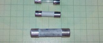
Tubular fuses
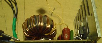
A fuse of a tubular design is a glass or ceramic tube, closed at the ends with metal caps, which are connected to each other by a wire of calibrated diameter running inside the tube. You can see the appearance of tubular fuses in the photograph.
The wire is spot welded to the caps or soldered with solder. In fuses designed for very high currents, the cavity inside the tube is often filled with quartz sand.
Automotive fuses
Fuses in cars rarely fail. Usually only in cases where the equipment fails. Most often when the headlight bulbs burn out. The fact is that when the filament of a light bulb breaks, a Voltaic arc is formed, the filament burns out and becomes shorter, the resistance sharply decreases and the current increases many times over.
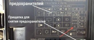
It happens that a fuse in a car burns out when the windshield wipers jam. Less often during short circuits in electrical wiring. In the photo you see widely used automotive blade (fork) type fuses. Below each fuse is the current of its protection in amperes.
A blown fuse in a car should be replaced with a fuse of the same rating, but it can also be repaired by replacing the blown wire in the fuse with a copper wire of the appropriate diameter. The voltage of the car's on-board network does not matter. The main thing is the correspondence of the protection current. If it is difficult to determine the rating of a blown car fuse, then you can use color coding.
Homemade fusible link from a conductor, selection by cross-section
Under no circumstances should you accept making your own fuse links FOR THE NORM. Installation of such products can be considered as a TEMPORARY MEASURE.
Diameters of COPPER wire for fuse link
| Diameter, mm | Current, A | Diameter, mm | Current, A |
| Ø 0.05 mm | 0.6 A | Ø 0.71 mm | 47.8 A |
| Ø 0.063 mm | 1.25 A | Ø 0.75 mm | 52 A |
| Ø 0.071mm | 1.5 A | Ø 0.8 mm | 57.2 A |
| Ø 0.08 mm | 1.8 A | Ø 0.85 mm | 62.7 A |
| Ø 0.09 mm | 2.1 A | Ø 0.9 mm | 68.3 A |
| Ø 0.1 mm | 2.5 A | Ø 0.95 mm | 68.6 A |
| Ø 0.112 mm | 3 A | Ø 1.0 mm | 80 A |
| Ø 0.124 mm | 3.5 A | Ø 1.06 mm | 87.3 A |
| Ø 0.14 mm | 4.2 A | Ø 1.12 mm | 94.8 A |
| Ø 0.16 mm | 5.1 A | Ø 1.18 mm | 102.5 A |
| Ø 0.17 mm | 5.6 A | Ø 1.25 mm | 111.8 A |
| Ø 0.18 mm | 6.1 A | Ø 1.32 mm | 121.3 A |
| Ø 0.2 mm | 7.1 A | Ø 1.4 mm | 132.5 A |
| Ø 0.224 mm | 8.4 A | Ø 1.45 mm | 139.7 A |
| Ø 0.25 mm | 10 A | Ø 1.50 mm | 147 A |
| Ø 0.28 mm | 11.8 A | Ø 1.6 mm | 161.9 A |
| Ø 0.315 mm | 14.1 A | Ø 1.7 mm | 177.3 A |
| Ø 0.335 mm | 15.5 A | Ø 1.8 mm | 193.2 A |
| Ø 0.355 mm | 16.9 A | Ø 1.9 mm | 209.5 A |
| Ø 0.4 mm | 20.2 A | Ø 2.0 mm | 226.2 A |
| Ø 0.45 mm | 24.1 A | Ø 2.12 mm | 247 A |
| Ø 0.5 mm | 28.2 A | Ø 2.24 mm | 268.2 A |
| Ø 0.56 mm | 33.5 A | Ø 2.36 mm | 290 A |
| Ø 0.63 mm | 40 A | Ø 2.5 mm | 316.2 A |
| Ø 0.67 mm | 43.7 A |
For repairing fuses with protection current from 0.25 to 50A
| Fuse protection current, Ampere | 0,25 | 0.5 | 1.0 | 2.0 | 3.0 | 5.0 | 7.0 | 10.0 | 15.0 | 20.0 | 25.0 | 30.0 | 35.0 | 40.0 | 45.0 | 50.0 | |
| Wire diameter, mm | Copper | 0.01 | 0.02 | 0.04 | 0.07 | 0.10 | 0.18 | 0.20 | 0.25 | 0.32 | 0.39 | 0.46 | 0.52 | 0.58 | 0.63 | 0.68 | 0.73 |
| Aluminum | — | — | 0.07 | 0.10 | 0.14 | 0.19 | 0.25 | 0.30 | 0.40 | 0.48 | 0.56 | 0.64 | 0.70 | 0.77 | 0.83 | 0.89 | |
| Steel | — | — | 0.32 | 0.20 | 0.25 | 0.35 | 0.45 | 0.55 | 0.72 | 0.87 | 1.00 | 1.15 | 1.26 | 1.38 | 1.50 | 1.60 | |
| Tin | — | — | 0.18 | 0.28 | 0.38 | 0.53 | 0.66 | 0.85 | 1.02 | 1.33 | 1.56 | 1.77 | 1.95 | 2.14 | 2.30 | 2.45 | |
For repairing fuses with protection current from 60 to 300A
| Fuse protection current, Ampere | 60 | 70 | 80 | 90 | 100 | 120 | 160 | 180 | 200 | 225 | 250 | 275 | 300 | |
| Wire diameter, mm | Copper | 0.82 | 0.91 | 1.00 | 1.08 | 1.15 | 1.31 | 1.57 | 1.72 | 1.84 | 1.99 | 1.14 | 2.20 | 2.40 |
| Aluminum | 1.00 | 1.10 | 1.22 | 1.32 | 1.42 | 1.60 | 1.94 | 2.10 | 2.25 | 2.45 | 2.60 | 2.80 | 2.95 | |
| Steel | 1.80 | 2.00 | 2.20 | 2.38 | 2.55 | 2.85 | 3.20 | 3.70 | 4.05 | 4.40 | 4.70 | 5.0 | 5.30 | |
| Tin | 2.80 | 3.10 | 3.40 | 3.65 | 3.90 | 4.45 | 4.90 | 5.80 | 6.20 | 6.75 | 7.25 | 7.70 | 8.20 | |
Protection by circuit breakers
3.1. Design and operating principle of AB
A modern circuit breaker (CB) is a complex multifunctional electrical device with multiple actions, which allows it to be used when implementing network automation circuits (AVR, AR). AVs are installed in direct and alternating current networks and are used to turn on and off electric circuits, to protect electrical installations from overloads, short circuits and unacceptable voltage drops. Therefore, they are widely used in AC installations with voltages up to 660 V.
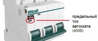
AVs play the same role as fuses, but have a more complex design, and AVs are much more convenient to use, Fig. 5. AVs are easily restored (switched on), do not require replacement, and simultaneously turn off the power in all three phases, and not in one damaged core, which provides more effective protection of the EO compared to protection with fuses, which eliminates the operation of the EO in open-phase mode.
Figure 5 – Various types of circuit breakers
This is important, since after the disappearance of one phase the ED would continue to operate on two, which is an emergency mode of operation and can lead to its damage, Fig. 6. It is convenient to use switches when carrying out routine repairs.
AB consists of a housing, arc chutes, control and switching mechanisms, and releases (Fig. 7). To turn on the breaker, which is in the disengaged position (position “Disconnected automatically”), the mechanism must be cocked by moving the handle (9) of the switch in the direction of the “O” sign until it stops.
In this case, the lever (10) engages with the latch (11), and the latch engages with the trip rail (12). Switching on is carried out by moving the handle (9) in the direction of the “1” sign until it stops. The failure of the contacts and contact compression when turned on is ensured by the displacement of the movable contacts (18) relative to the contact holder (17).
a b
Figure 6 – Diagram (a) and response characteristics (b) of the circuit breaker: 1 – contacts; 2 – free release mechanisms; 3 – leakage current transformer; 4 – amplifier-converter; 5 – button for checking the serviceability of the switch; 6 – EP; 7 – switch operation characteristics; 8 – limit of risk of cardiac fibrillation
The AB is switched off when the trip rack (12) is turned by the release, regardless of the position of the AB handle (9). In this case, the handle occupies an intermediate position between the signs “O” and “1”, indicating that the switch is turned off automatically. Arcing chambers (2) are installed in each pole of the switch and are deionic grids consisting of a series of steel plates (6).
Spark arresters containing spark arresting plates (3) and (4) are fixed in the cover (5) of the switch in front of the gas outlet holes in each pole AB. If in the protected circuit at least on one pole the current reaches a value equal to or greater than the current setting value, the corresponding release is triggered and the circuit breaker turns off the protected circuit.
Figure 7 – Design of the VA 04-36 circuit breaker: 1 – base, 2 – arc extinguishing chamber, 3 and 4 – spark arresting plates, 5 – cover, 6 – steel plates. 7 and 8 – link, 9 – handle, 10 – support lever, 11 – latch, 12 – trip rail, 13 – thermobimetallic plate, 14 – electromagnetic release, 15 – flexible conductor, 16 – current conductor, 17 – contact holder, 18 – contacts movable
An electromagnetic overcurrent release (14) is installed in each pole of the circuit breaker. The release performs the function of instantaneous short circuit protection. Low voltage circuit breakers are equipped with built-in releases of various types:
- electromagnetic or electronic overcurrent release, instantaneous or delayed. The response speed is practically independent of the current value;
- electrothermal or electronic inertial overcurrent release with a current-dependent time delay;
- leakage current release;
- undervoltage release;
- reverse current or reverse power release;
- independent release (for remote tripping of the circuit breaker).
The first two types of releases are installed on all poles, the remaining releases are installed one per switch. The currents of the AV operation setting, as well as the current time delay releases, can be adjustable. One or more types of current releases can be used in one circuit breaker and, in addition to them, an undervoltage release, an independent release and a switching electromagnet can be installed.
According to the response time, electromagnetic and electronic releases have four types:
- releases that ensure the operation of the circuit breaker in a time much less than 0.01 s, and cut off the short-circuit current before it reaches its impact value. Such AVs are called current-limiting;
- releases that ensure that the short-circuit current is switched off when the current first passes through the zero value (t = 0.01 s);
- unregulated releases whose response time exceeds 0.01 s;
- releases with an adjustable time delay (0.1÷0.7 s), allowing them to operate slowly relative to other circuit breakers in the same network. They are called selective.
Independent releases are used for local remote and automatic switching off of circuit breakers when external protective devices are triggered. Reverse current or reverse power releases are used to protect against loss of synchronism of SGs operating on the electrical network.
3.2. Calculation and selection of circuit breaker
AB is selected in compliance with the following requirements:
1) UNaut > UNnetwork, where UNaut is the rated voltage of the machine, V;
UNnetwork – rated voltage of the protected section of the network, V;
2) INrast ≥ Irast, A, where INrast is the rated current of the release, A;
Icalc – calculated current of the protected section of the network, A.
For single electric motors protected by AB, we consider that
Icalc = IN, where IN is the rated current of the motor, A.
If the protected network element operates in technological overload mode, then it is necessary to select circuit breakers with an adjustable slow-acting release, which are not turned off by the electronic device during planned overloads, but provide protection in emergency modes. The delayed response setting of adjustable releases providing overload protection Iset.p is selected according to the expression, A:
When choosing the current setting for the instantaneous operation of an electromagnetic release that provides short-circuit protection, it is necessary to adjust from short-term overloads (take a large shutdown current) caused by starting (self-starting) of motors, A:
where Iper (or Ipeak) is the short-term overload current (or peak current), determined depending on the nature of the load of the protected section of the network:
1) for single engines, A:
where kstart is the multiplicity of the motor starting current;
2) for self-starting EDs, A:
where is the sum of currents arising during self-starting of the electric motor, A;
3) to start a powerful engine and ensure normal operation of all other electric devices connected to the protected line, condition A must be met:
Where is the sum of the rated currents of the motors connected to the protected line, excluding the most powerful motor, A;
Istart.max – starting current of the most powerful electric motor in the protected section of the network, A; kc is the demand coefficient, kc <1.
AB is selected according to the rated current of the circuit breaker (IN.off) and the rated current of the release (IN.rast), A:
where Idl.lin = IN – continuous current in the line equal to the rated current of the motor, A:
where PN is the rated power of the engine, kW;
UN – rated voltage of the electric motor, kV; ηN – engine efficiency, p.u.;
cosφ – engine power factor, p.u.;
kt – coefficient taking into account the conditions of installation of the AV: with an open installation kt = 1; when installed in closed cabinets kt = 0.85.
After determining the rated currents of the motors protected by the AV, the starting current of the motors is determined taking into account its multiplicity, A:
For IM, the starting current multiplicity kstart = 5÷8.
Peak current in calculations is taken as follows:
Ipeak = Istart.max.motor+ΣIwork,
where Istart.max.motor is the starting current of the largest motor, A.
Let's calculate the rated current of the release, taking into account the correction factor kt = 0.85 and the fact that the circuit breakers are mounted in cabinets, which impairs heat transfer:
To isolate from starting currents (ensuring the impossibility of tripping the release), you should set the trip current of the release (Israb.ras), which is 25% higher than the maximum starting current of the motor (Istart), A:
This means that the AV should not operate until the starting current exceeds the rated current by 25%. This is the allowed range. Based on the data obtained, the AB is selected from the catalog tables, where the nomenclature of the manufacturer is indicated. Based on the post-emergency current, taking into account the thermal correction coefficient, the rated current of the selective circuit breaker is selected.
Input circuit breakers into the workshop SES are selected according to the installed capacity of the workshop transformers, taking into account their possible overload in post-emergency mode (according to GOST 14209-97), A:
All selected ABs check:
- for breaking capacity: low current three-phase short circuit;
- on the sensitivity of protection:
maxi-
– when protecting AB with delayed action releases, A:
where I(3)SCmin is the minimum single-phase short circuit current at an electrically remote point of the protected section of the network, A; INrast – rated current of the delayed release, A;
– when protected by automatic circuit breakers with instantaneous releases, A:
where Iset.KZ is the instantaneous operation setting current, A; “1.4” – coefficient for machines with IN < 100 A; “1.25” is the coefficient for machines with IN ≥ 100 A.
Replacing the fuse
When replacing a fuse, to avoid electric shock, be sure to unplug the electrical appliance!
There is an unspoken rule: if after the second replacement the fuse blows again, look for a fault in the electrical appliance itself. This means that the electrical appliance needs to be repaired.
Do not install a fuse at a higher current under any circumstances; such attempts will definitely lead to even greater damage to the device, up to the point of its being beyond repair!
Be careful when purchasing a new fuse. Correctly determine the type and current rating of the replacement candidate. It is better to purchase electronic components from trusted suppliers who guarantee product quality, such as Conrad Electronic.
Need for a fuse
Anything powered by a source with low internal resistance needs a fuse. This could be an electrical appliance that plugs into an outlet or is powered by a battery, or that runs off the alternator in your car. A low impedance source can provide enough current to melt conductive parts and start a fire (picture below). Insurance company laboratories were created to reduce the likelihood of a fire and, as a result, prevent insurance claims. The fuse can protect people from a short circuit to the frame, and also protect the electrical appliance from fire.
Fuse repair
Typical people believe that fuses cannot be repaired; in fact, this is not the case. Most types of fuses can be repaired and given a second, third, etc. life. The fuse housing, as a rule, is destroyed extremely rarely, the wire inside burns out, and the repair consists of replacing it. The main task is to use a wire similar to the one in the fuse.
If you need to replace a fuse very quickly, but you don’t have a spare at hand, you can use the following method:
Remove the paint coating from a wire of a suitable diameter (clean it until it shines) and wind several turns around each fuse contact, then insert the fuse into the holder. This method is popularly called “bug”. With its help you can very quickly check the serviceability of the device, but it is not reliable and can be used as a temporary solution to the problem.
The next method is the so-called “factory” one. Repairs will require a soldering iron, and perhaps a Dremel or screwdriver, but the fuse after repair will look like it came straight from the factory.
Heat the ends of the cup contacts with a soldering iron and remove the solder from the holes in the ends using a toothpick or something similar. It happens that the holes are too small or completely absent, then you will have to drill them. Use a drill of small diameter 1 - 2 mm.
Pass a wire of a suitable diameter through the holes and solder it to the cup contacts.
The fuse is ready!
Select fuse package
Your application will determine the type of fuse you will use. You may need a high voltage fuse. If your product is primarily sold in the US, then a standard of typically 1/4 inch (3.5 cm) is appropriate. In Europe, the 5 × 20 mm glass fuse is more common. For automotive applications, blade-lead fuses are used throughout the world. In industrial electrical cabinets you can see the industrial type of fuses. If you are protecting PCB traces, surface mount fuses are ideal (picture below).
It's often a simple matter of looking at products similar to yours to see what fuse they used. This can significantly help you make your choice.
Calculation of fuse wire diameter
To repair the fuse, it is necessary to replace the burnt wire. In the production of fuses in factories, depending on the current value and speed, calibrated silver, copper, aluminum, nickel, tin, lead and wires made of other metals are used.
For making a fuse at home, only red copper of calibrated diameter is available. All electrical wires are made of copper, and the more elastic the wire, the thinner the conductors and the greater the number of them. Therefore, all the technology proposed below is focused on the use of copper wire.
When choosing a fuse for equipment, developers use a simple law. The fuse current must be greater than the maximum consumed by the product. For example, if the maximum current consumption of the amplifier is 5 amperes, then the fuse is selected at 10 amperes. The first thing you need to do is find its marking on the fuse body, from which you can find out what current it is designed for. Often the current value is written on the product body, next to the location where the fuse is installed. Then, from the table below, determine what diameter wire is needed.
Fuse selection algorithm
The current-carrying capacity of the wire will be significantly higher than the expected current if the cross-section is chosen so that the voltage drop does not exceed 3%. To protect such a wire, a number of fuses are suitable, the ratings of which are located between the load current and the maximum permissible current of the wire. The fuse located in the upper part of the row heats up less and does not trip from an accidental surge of current. A lower rated fuse better protects the power wire.
- Using the table, find the maximum permissible fuse rating for a given wire cross-section. The higher the fuse rating, the less likely it will be to accidentally trip. But the worse he will defend the occasion. You need to choose the maximum rating taking into account the location of the wire (outside or inside the engine compartment) and taking into account the number of wires in the harness. Example: for one power wire with a cross-section of 25 mm2, located outside the engine compartment, the maximum fuse rating is 150 A. Open fuse selection table
- Calculate the minimum fuse rating. To do this, multiply the current consumed by the device by 1.25. The minimum rated fuse protects the wire better, but may trip accidentally. If the device consumes 80A, then the minimum fuse rating for a power wire with a cross-section of 25 mm2 is 80 x 1.25 = 100A.
- Select a fuse rating midway between the minimum and maximum values. Maximum value (step 1) – 150 A. Minimum value (step 2) – 100 A. Average value – (150 + 100) ÷ 2 = 125 A
At 125A there are MIDI, MRBF, MEGA and ANL fuses.
Ask a question,
and get advice on outboard electric motors, batteries or chargers for a boat or yacht
Operating principle of fuses
The principle of operation of disposable protective devices is very simple. Inside each of them there is a calibrated wire connecting the contacts. If the current value does not exceed the maximum permissible norms, it heats up to approximately 70 degrees. When the electric current exceeds the set rating, the heating of the wire increases significantly. At a certain temperature it begins to melt, resulting in a break in the electrical circuit. Wiring burnout occurs almost instantly. Because of this, fuses got their name - fuse link.
In different designs, the fuse link is selected in such a way that operation occurs at the set current value. During operation, fuses periodically fail and must be replaced. As a rule, they are not repaired, but many home craftsmen quite successfully restore them.
Since only the wire itself burns out, but the body remains intact, it is necessary to replace it and the device will continue to perform its functions. New technical characteristics are often not only not inferior to the old device, but also in many ways superior to it, since the quality of hand assembly is always higher than the factory one. The main condition is the correct choice of conductor material and calculation of its cross-section.
Cyclic loads
Cyclic loading, which leads to premature fuse fatigue, is determined by regular and irregular changes in load current. In this case, the current parameters must reach values that lead to deformation of the fuse elements. In order to avoid this, when choosing a fuse, a certain safety margin is included. Since it is impossible to establish a general rule for all situations, the additional coefficient G, determined empirically, is used. In most cases, the following value of the coefficient G = 1.6 is sufficient. Once a fuse has been selected, a test must be carried out to determine whether the safety margin is sufficient under intermittent surge load conditions. To do this, you need to determine the melting current It from the time-current characteristic of the fuse. The duration of one pulse from the cycle is taken as an argument. Next, follow the graph (Fig. 9) to find the cyclic pulsation coefficient B. Here, the pulse period T is used as an argument. In order for the fuse to reliably perform its functions, the permissible value of the pulse current must be less than the product of the melting current It and the coefficient B:
Ipulse< It × B. Let's look at an example. There is the following cyclic load: 150 A for 2 minutes followed by a change to 100 A for 15 minutes (Fig. 10).
We calculate the effective value of the current in the Irms circuit:
Assuming that there are no worsening parameters, we consider the G coefficient to be equal to 1.6. We get In > Irms × G = 107 × 1.6 = 171 A. According to the first estimate, a 200 A fuse is sufficient in this case. Let us now check the safety margin for the B-factor. The pulse duration (Fig. 10) is 120 s. Using the time-current characteristic (Fig. 11), we determine the melting current It for 120 s. It is equal to 440 A.
Next, from the graph (Fig. 10) we calculate the cycle period T. It is 120 s + 15 min = 17 min. According to the graph (Fig. 12), we determine coefficient B for 17 minutes. The B coefficient is 0.32. Let's check the fulfillment of the reliability condition when working with this cyclic load. Multiplying the factor B by the melting current, we get 440 × 0.32 = 141 A, which is less than the pulse current of 150 A.
This means that with such a cyclic load, a 200 A fuse will not have a sufficient safety margin. The fuse rating needs to be increased. By carrying out such checks, we can guarantee long-term operation of the fuse under conditions of pulsed cyclic load. Sometimes, as a result of calculations, it turns out that the thermal energy indicator I2t of the fuse becomes greater than that of the protected device, for example an IGBT module. In this case, the fuse will be unable to perform its intended functions. In such situations, it is worth slightly reducing the safety margin of the fuse, or, if the strength decreases significantly, you will have to choose a different fuse model. In addition to the selection of the main parameters of the fuse, discussed above and which are decisive, there are also other criteria, for example, design, type of contacts, presence of operation indication, etc.
Causes of blown fuses
Let's start with the most important thing - the reasons for blown fuses. After all, nothing just happens, and before installing a bug, you need to determine the reasons for the fuse failure.
There may be several of them:
Fuse links. How to choose and calculate current. Operation and Application
Fuse links are electrical elements for protecting equipment from short circuits and overvoltage by turning off power when current load limits are exceeded. Opening the circuit occurs due to the melting of a safety wire of a certain thickness. Several types of these devices are known to the industry. They all differ in internal and external design features, but function according to the same principle.
Nowadays, in order to protect household electrical equipment, more practical reusable circuit breakers are used, but disposable fusible links are still found in plugs. They are especially relevant for premises of temporary and old buildings, where the installation of effective modern shields is not economically justified. In household appliances, there is still no alternative to the classic fuse.
Fuse links are also actively used in industry. The performance of an entire plant or utility network may depend on them. It is better not to buy industrial fuses secondhand, on the market or from unverified organizations. A wise decision is to turn to electronics professionals, for example, the online store Conrad.ru. In such matters, the miser pays not twice, but three times
Selection and testing of protective equipment up to 1 kV
A protection device is a device that automatically turns off the protected electrical circuit in the event of a short circuit or overload.
An electrical receiver can be one or a group of synchronous or asynchronous electric motors, transformers, electric furnaces, converters, electric lighting, etc. All existing or newly constructed electrical networks must be provided with necessary and sufficient means of protecting sections of circuits and electrical equipment from overload currents, currents Short circuit and from peak currents. At the same time, it is also necessary to protect people working with these networks from electric shock.
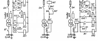
In Fig. 1 shows possible IM protection schemes.
Figure 1 – Protection schemes for an asynchronous motor: a – with a QF circuit breaker and a combined release; b – with a QF circuit breaker and a combined release and thermal protection (KK); c – with fuse FU and thermal protection (KK)
Each transformer substation, each overhead line, each cable line and intra-house distribution networks, each electrical installation has its own protection devices that ensure their uninterrupted and reliable operation. Such devices are selected by type, connection method and protection parameters. They come in different types:
- fuses with fusible links;
- automatic switches (AB);
- relays (current, thermal, voltage, etc.).
We choose the diameter of the fuse wire - we analyze all the subtleties of the issue
A homemade copper wire fuse can be a great temporary way to replace a blown fuse. But if you decide to do this, then it is extremely important to choose the right cross-section of the very conductor that you will use. Why is this important, what are the reasons for blown fuses and ways to temporarily eliminate this inconvenience we will consider in our article.
How to determine the fuse rating from the case and on the board
Before you change something that has gone bad, you need to understand what has gone bad. In our case it burned out. Here you can rely only on the inscription on the board itself or on the fuse, because other methods of finding out what the fuse rating was are very unsteady and groundless. After all, a serviceable fuse will not show anything as zero resistance, but a faulty break. At the same time, do not send it to the laboratory for analysis in order to find out what kind of material it was. Let's look at examples of designation of fuses on the board and SMD elements. By the way, sometimes even a resistor can be used instead of a fuse.
Calculation of conductors for fuses
where: d – conductor diameter, mm; k – coefficient depending on the conductor material according to the table.
where: m is a coefficient depending on the conductor material according to the table.
Formula (1) is applied for low currents (thin conductors d=(0.02 - 0.2) mm), and formula (2) for high currents (thick conductors). Odds table.
The conductor diameter for use in a fuse is calculated using the formulas: For low currents (thin conductors with a diameter of 0.02 to 0.2 mm):
For high currents (thick conductors):
The amount of heat generated at the fuse link is calculated by the formula:
where: I – current flowing through the conductor; R – conductor resistance; t – time the fuse-link is under current I.
The resistance of the fuse link is calculated by the formula:
where: p – resistivity of the conductor material; l – conductor length; s is the cross-sectional area of the conductor.
To simplify calculations, the resistance is assumed to be constant. The increase in resistance of the fuse link due to increased temperature is not taken into account.
Knowing the amount of heat required to melt the fuse link, you can calculate the melting time using the formula:
where: W is the amount of heat required to melt the fuse link; I—melting current; R is the resistance of the fuse link.
Arc extinguishing systems in circuit breakers
4.1. Types of arc extinguishing systems in AV
Arc extinguishing systems are the main elements of the AB design, because An open circuit may result in an electrical arc that arc extinguishing systems must “extinguish.” The arc extinguishing system consists of metal plates fixed parallel to each other, which crush, neutralize or break the electric arc, depending on the design.
Gas arc extinguishing systems are used in AC circuit breakers. With gas arc extinguishing, an electric arc burns in gas flows, where it cools, bends, elongates and breaks.
Types of gas arc extinguishing systems:
- gas arc extinguishing - when an arc appears, the rupture zone heats up, heats up special gas-generating substances (plexiglass, fiber) and gas flows expand. The resulting gas contains a large amount of hydrogen, which has a high heat capacity and provides intense heat removal from the arc. Gas arc extinguishing is used in disposable devices (fuses with fuse links), in arresters and in oil circuit breakers;
- with air arc extinguishing a stream of compressed air acts on the arc. Air arc extinguishing can be:
- transverse - used in AV with voltage no more than 15 kV;
- longitudinal - used in AV DC networks of electric locomotives.
- Magnetic Arc Extinguishing Systems
The operation of a magnetic arc extinguishing system is based on the interaction of an electric arc with a magnetic field: under the influence of the field, the electric arc moves in space, lengthens and breaks. Magnetic arc extinguishing systems are classified:
- permanent magnet arc extinguishing systems . The disadvantages of such systems include low permissible current loads, high price and fragility of magnet materials;
- arc extinguishing systems with electromagnetic blast (electrodynamic magnetic arc extinguishing). In these systems, arc extinction is based on the interaction of the electric arc with its own magnetic field and the magnetic field of the current-carrying parts of the circuit breaker. The electric arc that occurs between the contacts moves perpendicular to the magnetic field lines, is transferred to the arc extinguishing “horns,” lengthens and breaks. The advantages of such systems include simplicity, the absence of additional devices, and maintaining a constant direction of the electromagnetic force when the direction of the current changes. The disadvantage is that sometimes the lengthening of the magnetic arc is not enough to cause rupture (arc extinguishing);
- electromagnetic arc suppression , based on the interaction of an electric arc with an external magnetic field created by special devices consisting of an excitation coil (arc coil) and a magnetic core. Arc extinguishing coils are available with sequential and independent winding connections.
Each of these systems has advantages and disadvantages :
- in systems with sequential excitation, the advantages include the fact that the resulting force is proportional to the current and does not change its direction when the direction of the current changes. The disadvantage is that at low currents there are difficulties in extinguishing the arc due to the small magnitude of the resulting force;
- in systems with independent excitation, the advantage is that the coil is powered from a separate source and the magnitude of the resulting force does not depend on the magnitude of the current in the circuit. A disadvantage is the need to change the direction of the current in the arc extinguishing coil when the direction of the load current changes.
What do copper wire fuses look like and do?
In appearance, a fuse is a glass or ceramic flask with a calibrated copper wire stretched inside it. It is attached to the element contacts located in the metal caps using soldering or spot welding. The diameter of the wire depends on the current for which the fuse is designed. The flask (tube) of a product with a high rated current is sometimes filled with quartz sand. Because of their appearance, such fuses are called tubular.
Another common type of this device is knife-type automotive fuse links. Depending on the current rating, they are painted in different colors:
- 5 A - orange;
- 7.5 A - brown;
- 10 A - red;
- 15 A - blue;
- 20 A - yellow;
- 25 A - colorless (transparent);
- 30 A - green;
- 40 A - purple;
- 60 A - blue;
- 70 A - black.
The operating principle of the insert is extremely simple. The fuse is turned on and electric current begins to flow through the wire. The wire heats up. As long as the current does not exceed the fuse rating, the wire temperature remains at approximately 70 degrees Celsius. As soon as the current values exceed the permissible limits, the heating of the wire increases to the melting temperature of copper, it loses its integrity, thus breaking the electrical circuit. All this happens very quickly, almost in a split second. It is because of this principle of operation that fuses with copper wire are called fuse links.
There are different types and types of such inserts. But regardless of this, they all act the same way: the copper wire they contain melts and the current flow is interrupted.
It is very important to understand that the fuse “trips” precisely when the permissible current value is exceeded, but the voltage in the network has no meaning for it. In other words, the same element can be installed in both a 12-volt charger and a single-phase or three-phase network.
Naturally, the question may arise: we say that the device protects against power surges in the network, and then we claim that voltage is not important for it, how is this possible? In fact, here it is enough to recall the school physics course, namely Ohm’s law, which states that the current strength in a section of a circuit is directly proportional to the voltage and inversely proportional to the resistance. In other words, the higher the voltage, the higher the current, given that the resistance of the conductor (copper wire of a certain diameter) in any case remains unchanged.
An insert can burn out not only due to voltage surges in the network, that is, due to exceeding the rated current, but also due to a malfunction inside the device itself in which it is installed. You can determine the reason for the failure of the insert yourself - if after replacing it twice, the element burns out again, it means that the device itself is faulty. Sometimes a situation occurs when the reason for the failure of an insert is its poor quality, but this is rare.
Determining the rated current value of the fuse
The rated current of a fuse is the root mean square value of the current that the fuse is capable of passing for a long time without deteriorating its properties and without the temperature exceeding acceptable limits. For correct operation of the fuse, it is necessary to select the correct rated current value. It depends both on the parameters of the protected circuit and on many external factors. At elevated ambient temperatures, the rated current of the fuse should be increased, and at low temperatures or with forced cooling by air flow, it should be reduced. This value is also influenced by the frequency of the current, the current density in the contact area, atmospheric pressure (at altitudes above 2000 m above sea level), as well as the duration and frequency of exposure to overload currents. All these parameters are related to the rated current of the fuse by the following formula:
In = Ib / (Kt × Ke × Kv × Kf × Ka × Kb), where In is the rated current of the fuse; Ib is the rms maximum load current in the circuit, operating for a long time; Kt—air temperature coefficient; Ke is the contact current density coefficient; Kv - air flow coefficient; Kf—current frequency coefficient; Ka is the altitude coefficient; Kb is the constant (const) load of the fuse. Bussmann technical documentation specifies the rated fuse current for an ambient temperature of 20 °C.
However, in actual operating conditions the temperature may differ from this value. An increase in the temperature of the environment, for example, in closed installation conditions or in the case of proximity to heat-loaded elements, makes it necessary to select a fuse of a higher rating, since less heat will be required to melt the jumper. Conversely, lower ambient temperatures require the use of a fuse with a lower current rating. The graph for determining the correction factor depending on the ambient temperature for a typical fast-acting fuse is shown in Fig. 4.
Thus, if the ambient temperature is about 60 ° C, then with a current in the circuit of 100 A, you need to use a 100 A / 0.8 = 125 A fuse. To assess the influence of air, various empirical formulas and dependencies are used. When forced air cooling of fuses is carried out at a flow speed of 2–10 m/s, it is permissible to use a fuse of a lower rating. From the graph in Fig. 5 it can be seen that already with an air flow of 2 m/s for a circuit with a maximum current of 1100 A, a fuse with a rated current of 1000 A should be used.
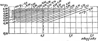
It should be noted that the air flow speed should be taken directly from the fuse housing, and not from the fan impeller. High performance of fuses is achieved by increasing the current density in the isthmuses of the fusible elements, which causes strong heating of the fuse body. Consequently, the cross-section and length of the current-carrying busbars have a great influence on the characteristics of the fuse. About 70% of the heat generated in the fuse is removed through the busbars. Therefore, increasing their cross-section can provide an increase in the rated current by several percent. According to the recommendations of Bussmann specialists, the current density in the busbars should be 1.3 A/mm2 (according to IEC 60269, part 4, the current density can be in the range of 1–1.6 A/mm2). If the actual current density in the busbars is greater than this value, then the fuse rating should be increased, using for calculation the coefficient determined from the graph shown in Fig. 6.
For example, a 200 A rectangular fuse is installed on a busbar with a cross-section of 100 mm2. The current density is 200/100 = 2 A/mm2. To meet the requirement of 1.3 A/mm2, the recommended busbar section should be 200/1.3 = 154 mm2. The actual tire size is 100/154 = 65% of the recommended value. Having determined the Ke coefficient from the graph, we obtain the rated current of the fuse 200/0.94 = 213 A. If both connected buses are not the same, then the Ke coefficient can be calculated using the formula: Ke = (Ke1 + Ke2) / 2. Fuses operating in high-frequency chains require special attention. Under such conditions, their current-carrying abilities may be reduced due to the occurrence of skin effect and proximity effect on the conductive elements of the fuse. The skin effect is expressed in an increase in current density from the center to the surface of the conductor. This is due to the phenomenon of displacement of current in a conductor under the influence of its own magnetic field. The proximity effect is expressed as a shift in current density due to the action of current in nearby conductors. Both of these induction effects create an uneven distribution of current across the cross-section of the conductor, which leads to increased heat generation. To take them into account, a correction factor for the current frequency Kf is introduced, determined from the graph shown in Fig. 7.
The graph shows that at a current of 100 A with a frequency of 10 kHz, you need to use a fuse of 100/0.7 = 143 A. When fuses are used, for example, in the mountains, convection cooling worsens due to a decrease in atmospheric density. Therefore, at altitudes above 2000 m above sea level, the altitude coefficient above sea level is used, calculated by the formula: Ka = (1 – (h – 2000)/20000), where h is the altitude in meters above sea level. So, at an altitude of 5000 m in a circuit with a current of 85 A, a fuse of 85/(1 – (5000 – 2000)/20000) = 100 A should be used. The constant (const) load of the fuse Kb is determined from the technical description of the fuse. It depends on the material of the fuse housing. So, for porcelain fuses its value is 1, and for a fiberglass body it is 0.8.